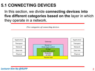
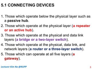
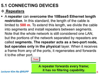
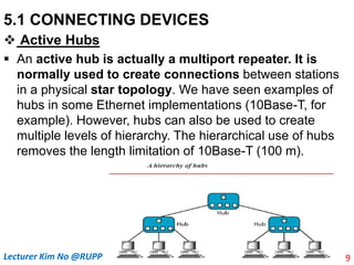
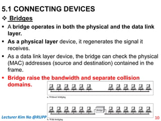
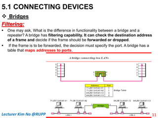
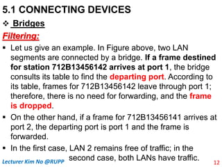
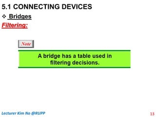
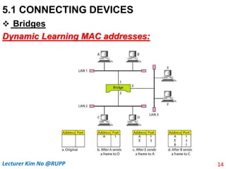
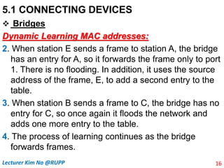
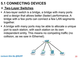
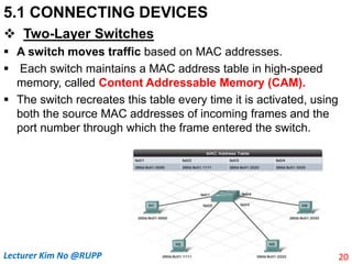
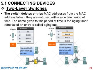
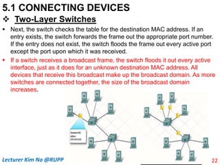
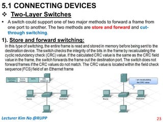
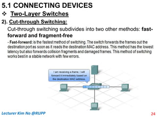
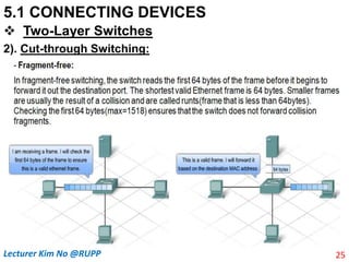
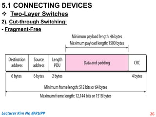
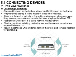
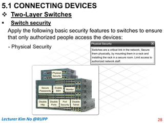
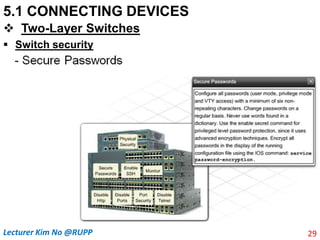
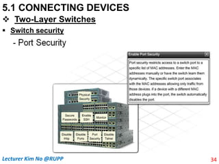
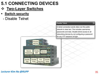
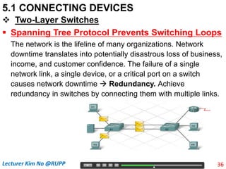
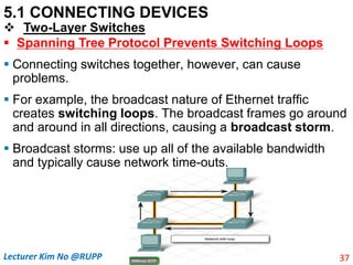
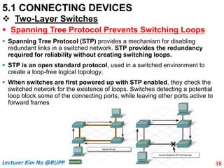
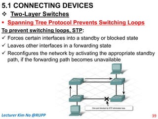
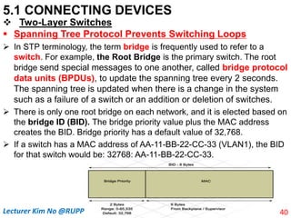
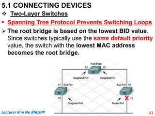
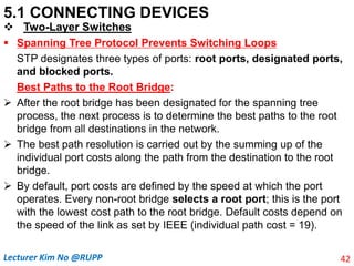
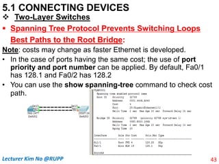
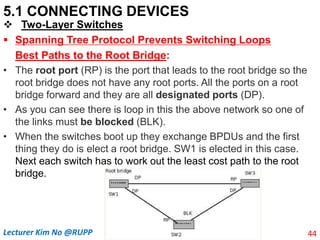
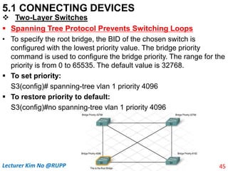
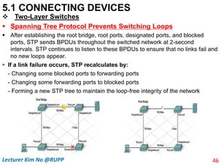
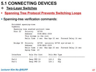
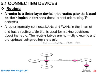
The document discusses different types of connecting devices that can be used to connect local area networks (LANs) and network segments. It describes devices that operate at different layers of the OSI model, including passive hubs (below physical layer), repeaters (physical layer), bridges (physical and data link layers), routers (physical, data link, and network layers), and gateways (all five layers). It focuses on bridges and switches, explaining how they learn MAC addresses dynamically and use filtering to reduce traffic. The document also covers spanning tree protocol, which prevents switching loops by disabling redundant links.
![5.1 CONNECTING DEVICES
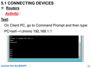
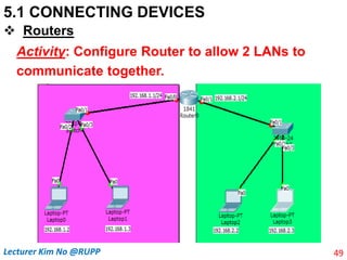
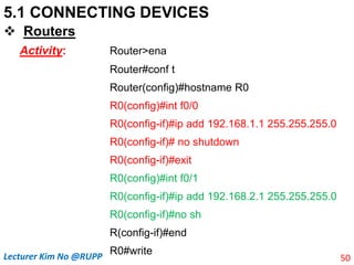
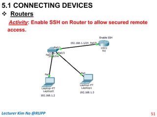
Routers
Activity:
Router>ena
Router#conf t
Router(config)#hostname R0
R0(config)#line console 0
R0(config-line)#password 12345
R0(config-line)#login
R0(config-line)#exit
R0(config)#ena secret 12345
R0(config)#int f0/0
R0(config-if)#ip add 192.168.1.1
255.255.255.0
R0(config-if)#no sh
R0(config-if)exit
R0(config)! Note Enable SSH
R0(config)#ip domain-name demo.com
R0(config)#crypto key generate rsa
The name for the keys will be:
R0.demo.comChoose the size of the key
modulus in the range of 360 to 2048 for
your General Purpose Keys. Choosing a
key modulus greater than 512 may take a
few minutes.
How many bits in the modulus [512]: 2048
R0(config)#username chumno pass 12345
R0(config)#line vty 04
R0(config-line)#login local
R0(config-line)#transport input ssh
R0(config-line)#end
R0#write
52
Lecturer Kim No @RUPP](https://image.slidesharecdn.com/chapterv-connectinglansbackbonenetworksandvirtuallans-230705003513-10a1861a/85/Chapter-V-Connecting-LANs-Backbone-Networks-and-Virtual-LANs-pptx-50-320.jpg)