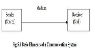
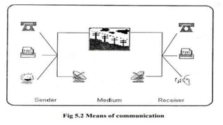
UNIT 4
DATA COMMUNICATIONS
Computer application in management
Unit Outline
4.1 Introduction
4.2 Basic Elements of a Communication System
4.2.1 Data Transmission Modes
4.2.2 Transmission Basics
4.3 Types of Data Transmission Media
4.3.1 Bounded Media
4.3.2 Unbounded Media
4.4 Modulation Techniques
4.4.1 Modems
4.4.2 Analog versus Digital Transmission
4.5 Multiplexing
4.5.1 Time Division Multiplexing (TDM)
4.5.2 Frequency Division Multiplexing (FDM)
4.1 Introduction
Data Communications
concerns the transmission of
digital messages to devices
external to the message
source.
4.2 Basic Elements of a Communication System
Communication is the
process of transferring
messages and data from one
point to another.
The three basic elements of any
communication process are:
1) A sender (source) which creates the
message to be transmitted.
2) A medium which carries the message.
3) A receiver (Sink) which receives the
message.
For example
when we speak to our friend over
telephone we are sender,
the telephone line through which our
voice is transmitted is a medium and
our friend is a receiver.
This is a simple example of voice
communication. The same concept
holds for the data communication also.
4.2.1 Data Transmission Modes
Data transmission, whether
analog or digital, may also be
characterized by the direction
in which the signals travel over
the media.
1. Simplex:
Data is sent from sender to
receiver.
Signals may travel in only one
direction.
Simplex is sometimes called
one-way, or unidirectional
communication.
Real-life examples of full communication
include:
 Radio broadcasting
Television broadcasting
Computer to print
Monitor output
Mouse /keyboard to computer
Loud speaker
•Advantage of simplex mode
 simplex mode is the easiest and mos reliable
mode of communication
 Is cost-effective mode
 No need for coordination b/n the transmitting
and receiving devices which simplifies the
communication
•Disadvantage of simplex mode
 Only one way communication is possible.
 There is no way to verify if the transmitted
data has been received correctly.
 Simplex mode is not suitable for application
that require bidirectional communication
2. Half Duplex
 Data can transmit both ways, but not
simultaneously
Signals may travel in both directions
over a medium but in only one
direction at a time.
Half-duplex systems contain only one
channel for communication, and that
channel must be shared for multiple
nodes to exchange information.
Real-life examples of full
communication include:
A two-way radio that has a
push-to-talk button
Browsing the internet(requests
and responses)
Universal Serial Bus (USB)
•Advantage of Half-duplex mode
 Half-duplex mode allows for bidirectional
communication, which is useful in situations
where devices need to send and receive data.
 it is a more efficient mode of communication
than simplex mode, the channel can be used for
both transmission and reception.
 Half-duplex mode is less expensive than full-
duplex mode, as it only requires one
communication channel.
•Disadvantage of Half-duplex mode
 Half-duplex mode is less reliable than full-
duplex mode, as both devices cannot transmit at
the same time.
 There is delay b/n transmission and reception,
which can cause problems in some application.
 There is need for coordination b/n the
transmitting and receiving devices, which can
complicate the communication process.
3. Full-Duplex
Signals are free to travel in both
directions over a medium
simultaneously.
Data can transmit both ways at the
same time.
Full duplex may also be called
bi-directional transmission or
sometimes, simply duplex.
Real-life examples of full
communication include:
 Video calls/video conferencing
 Audio calls
 Live chats
Advantage of Full-duplex mode
Full-duplex mode allows for simultaneous
bidirectional communication, which is ideal for
real-time application such as video conferencing
or online gaming.
It is the most efficient mode of communication,
as both devices can transmit and receive data
simultaneously.
Full-duplex mode provides a high level of
reliability and accuracy, as there is no need for
error correction mechanisms.
Disadvantage of Full-duplex mode
Full-duplex mode is the most expensive mode,
as it requires two communication channels.
It is more complex than simplex and half-duplex
mode, as it requires two physically separate
transmission paths or a division of channel
capacity.
Full-duplex mode may not suitable for all
applications, as it requires a high level of
bandwidth and may not be necessary for some
type of communication.
A channel is a distinct communication
path between two or more nodes.
4.2.2 Transmission Basics
In data networking, the term
transmission has two meanings.
First, it can refer to the process of
issuing data signals on a medium.
Second, it can also refer to the
progress of data signals over a
medium from one point to another.
Analog and Digital Signalling
One important characteristic of
data transmission is the type of
signalling involved.
 On a data network, information
can be transmitted via one of
two signalling methods:
i. Analog
ii. Digital
Both types of signals are
generated by electrical
current, the pressure of which
is measured in volts.
The strength of an electrical
signal is directly proportional
to its voltage.
The essential difference
between analog and digital
signals is the way voltage
creates and sustains the
signal.
1. Analog Signaling
In analog signals, voltage varies continuously.
In digital signals, voltage turns off and on
repeatedly, pulsing from zero voltage to a specific
positive voltage.
An analog signal’s voltage appears as a
continuous wave when graphed over time,
because voltage is varied and imprecise in analog
signals,
Analog transmission is more
susceptible/disposaed to transmission flaws such
as noise than digital signals.
2. Digital Signaling
Unlike analog signals where there
is a smooth curve, digital signals
jump directly to the next value.
When digital signals can exist in
only one of two values, they go
directly to the next value, typically
changing between 0 and 1.
The jump from one value to
another is known as a
transition.
Data rate is measured in bits
per second (bps).
Data rate: This is the rate, in bits
per second (bps), at which data can
be communicated.
Bandwidth: This is the maximum
bandwidth of the transmitted signal
as constrained by the nature of the
transmission medium or
transmission channel, expressed in
cycles per second, or hertz (Hz).
Noise: The average level of
noise over the communications
path.
Error rate: The rate at which
errors occur, where an error is
the reception of a 1 when a 0
was transmitted or the reception
of a 0 when a 1 was transmitted.
4.3 TYPES OF DATA TRANSMISSION MEDIA
Data Transmission Media is
divided into two types
1) Bounded Media
2) Unbounded Media
4.3.1 Bounded Media
Bounded Media is also known
as guided media.
Bounded media are great for
LANs because they offer high
speed, good security, and low
cost.
Three common types of bounded media
are:
a) Coaxial
b) Twisted pair
c) Fiber optic
a) Coaxial Cable
Coaxial cable consists of a
central copper core surrounded
by an insulator, a braided metal
shielding, called braiding, and an
outer cover, and called the
sheath or jacket.
Because of its insulation and
protective braiding, coaxial cable has
a high resistance to interference
from noise.
Coaxial cable is also less desirable
than twisted-pair because it
supports lower throughput.
b) Twisted-Pair Cable
The most popular network cabling
right now is twisted pair.
It is lightweight, easy to install,
inexpensive, and supports many
different types of networks.
It can also supports speeds of up
to 100Mbps.
Twisted-pair cabling is made up of
pairs of solid or stranded copper
twisted around each other.
The twists are done to reduce the
vulnerability to EMI and cross talk.
The number of pairs in the cable
depends on the type.
The copper core of the cable is usually
22-AWG or 24-AWG, as measured on
the American Wire Gauge standard.
Twisted-pair (TP) cable is
similar to telephone wiring and
consists of color-coded pairs of
insulated copper wires, each
with a diameter of 0.4 to 0.8
mm, or 22-24 AWG (American
Wire Gauge) standard copper
wires.
C. Fiber-Optic Cable
Fiber-optic cable, or simply fiber,
contains one or several glass fibers at
its center, or core.
Data are transmitted via pulsing light
sent from a laser or light-emitting
diode (LED) through the central fibers.
Surrounding the fibers is a layer of
glass called cladding.
4.3.2 Unbounded Media
Unbounded, or wireless, media does not
use any physical connectors between the
two devices communicating.
Usually the transmission is sent through
the atmosphere, but sometimes it can be
just across a room.
Wireless media is used when a physical
obstruction or distance blocks the use of
normal cable media.
Following are the types of unbounded media:
1. Radio Waves
i. Short-wave
ii. Very-high frequency (VHF)
television and radio
iii. Ultra-high frequency (UHF)
television and radio Micro waves
2. Microwaves
i. Terrestrial Microwaves
ii. Satellite Microwaves
3. Infrared
i. Point-to-point
ii. Broadcast
1. Radio Waves
Radio waves have
frequencies between 10 KHz
and 1GHz.
Radio waves include the following types:
i. Short-wave
ii. Very-high frequency (VHF) television and
radio
iii. Ultra-high frequency (UHF) television and
radio Micro waves
Most radio frequencies in the US
and Canada are regulated.
To gain permission to use a
regulated frequency can take a long
time and a large amount of money.
The good news is that there are
some frequencies that are not
regulated and anyone can use.
The problem with unregulated
frequencies is that they can get
saturated.
To ease this, there have been
limits set on the amount of
power that devices can
broadcast in these frequencies.
2. Microwaves
Microwaves travel at higher frequencies
than radio waves and provide better
throughput as a wireless network media.
Microwave transmissions require the
sender to be within sight of the receiver.
These systems use licensed frequencies,
which makes them more costly than radio
wave systems.
Microwaves are utilized on the following two types of
communication systems:
i. Terrestrial Microwaves
Terrestrial microwave transmissions are used to
transmit wireless signals across a few miles.
ii. Satellite Microwaves
Satellite microwave transmissions are used to transmit
signals throughout the world.
3. Infrared
Infrared frequencies are just
below visible light.
These high frequencies allow
high-speed data transmissions.
These transmissions fall into the following two
categories:
i. Point-to-point Infrared
Point-to-point infrared
transmissions utilize highly
focused beams to transfer signals
directly between two systems.
ii. Broadcast infrared
Broadcast infrared transmissions
use a spread signal, one broadcast
in all directions, instead of a direct
beam.

Computer application in management for third year

  • 1.
    UNIT 4 DATA COMMUNICATIONS Computerapplication in management
  • 2.
    Unit Outline 4.1 Introduction 4.2Basic Elements of a Communication System 4.2.1 Data Transmission Modes 4.2.2 Transmission Basics 4.3 Types of Data Transmission Media 4.3.1 Bounded Media 4.3.2 Unbounded Media 4.4 Modulation Techniques 4.4.1 Modems 4.4.2 Analog versus Digital Transmission 4.5 Multiplexing 4.5.1 Time Division Multiplexing (TDM) 4.5.2 Frequency Division Multiplexing (FDM)
  • 3.
    4.1 Introduction Data Communications concernsthe transmission of digital messages to devices external to the message source.
  • 4.
    4.2 Basic Elementsof a Communication System Communication is the process of transferring messages and data from one point to another.
  • 5.
    The three basicelements of any communication process are: 1) A sender (source) which creates the message to be transmitted. 2) A medium which carries the message. 3) A receiver (Sink) which receives the message.
  • 6.
    For example when wespeak to our friend over telephone we are sender, the telephone line through which our voice is transmitted is a medium and our friend is a receiver. This is a simple example of voice communication. The same concept holds for the data communication also.
  • 8.
    4.2.1 Data TransmissionModes Data transmission, whether analog or digital, may also be characterized by the direction in which the signals travel over the media.
  • 10.
    1. Simplex: Data issent from sender to receiver. Signals may travel in only one direction. Simplex is sometimes called one-way, or unidirectional communication.
  • 11.
    Real-life examples offull communication include:  Radio broadcasting Television broadcasting Computer to print Monitor output Mouse /keyboard to computer Loud speaker
  • 12.
    •Advantage of simplexmode  simplex mode is the easiest and mos reliable mode of communication  Is cost-effective mode  No need for coordination b/n the transmitting and receiving devices which simplifies the communication
  • 13.
    •Disadvantage of simplexmode  Only one way communication is possible.  There is no way to verify if the transmitted data has been received correctly.  Simplex mode is not suitable for application that require bidirectional communication
  • 15.
    2. Half Duplex Data can transmit both ways, but not simultaneously Signals may travel in both directions over a medium but in only one direction at a time. Half-duplex systems contain only one channel for communication, and that channel must be shared for multiple nodes to exchange information.
  • 16.
    Real-life examples offull communication include: A two-way radio that has a push-to-talk button Browsing the internet(requests and responses) Universal Serial Bus (USB)
  • 17.
    •Advantage of Half-duplexmode  Half-duplex mode allows for bidirectional communication, which is useful in situations where devices need to send and receive data.  it is a more efficient mode of communication than simplex mode, the channel can be used for both transmission and reception.  Half-duplex mode is less expensive than full- duplex mode, as it only requires one communication channel.
  • 18.
    •Disadvantage of Half-duplexmode  Half-duplex mode is less reliable than full- duplex mode, as both devices cannot transmit at the same time.  There is delay b/n transmission and reception, which can cause problems in some application.  There is need for coordination b/n the transmitting and receiving devices, which can complicate the communication process.
  • 20.
    3. Full-Duplex Signals arefree to travel in both directions over a medium simultaneously. Data can transmit both ways at the same time. Full duplex may also be called bi-directional transmission or sometimes, simply duplex.
  • 21.
    Real-life examples offull communication include:  Video calls/video conferencing  Audio calls  Live chats
  • 22.
    Advantage of Full-duplexmode Full-duplex mode allows for simultaneous bidirectional communication, which is ideal for real-time application such as video conferencing or online gaming. It is the most efficient mode of communication, as both devices can transmit and receive data simultaneously. Full-duplex mode provides a high level of reliability and accuracy, as there is no need for error correction mechanisms.
  • 23.
    Disadvantage of Full-duplexmode Full-duplex mode is the most expensive mode, as it requires two communication channels. It is more complex than simplex and half-duplex mode, as it requires two physically separate transmission paths or a division of channel capacity. Full-duplex mode may not suitable for all applications, as it requires a high level of bandwidth and may not be necessary for some type of communication.
  • 25.
    A channel isa distinct communication path between two or more nodes.
  • 26.
    4.2.2 Transmission Basics Indata networking, the term transmission has two meanings. First, it can refer to the process of issuing data signals on a medium. Second, it can also refer to the progress of data signals over a medium from one point to another.
  • 27.
    Analog and DigitalSignalling One important characteristic of data transmission is the type of signalling involved.  On a data network, information can be transmitted via one of two signalling methods:
  • 28.
  • 29.
    Both types ofsignals are generated by electrical current, the pressure of which is measured in volts. The strength of an electrical signal is directly proportional to its voltage.
  • 30.
    The essential difference betweenanalog and digital signals is the way voltage creates and sustains the signal.
  • 31.
    1. Analog Signaling Inanalog signals, voltage varies continuously. In digital signals, voltage turns off and on repeatedly, pulsing from zero voltage to a specific positive voltage. An analog signal’s voltage appears as a continuous wave when graphed over time, because voltage is varied and imprecise in analog signals, Analog transmission is more susceptible/disposaed to transmission flaws such as noise than digital signals.
  • 32.
    2. Digital Signaling Unlikeanalog signals where there is a smooth curve, digital signals jump directly to the next value. When digital signals can exist in only one of two values, they go directly to the next value, typically changing between 0 and 1.
  • 33.
    The jump fromone value to another is known as a transition. Data rate is measured in bits per second (bps).
  • 36.
    Data rate: Thisis the rate, in bits per second (bps), at which data can be communicated. Bandwidth: This is the maximum bandwidth of the transmitted signal as constrained by the nature of the transmission medium or transmission channel, expressed in cycles per second, or hertz (Hz).
  • 37.
    Noise: The averagelevel of noise over the communications path. Error rate: The rate at which errors occur, where an error is the reception of a 1 when a 0 was transmitted or the reception of a 0 when a 1 was transmitted.
  • 38.
    4.3 TYPES OFDATA TRANSMISSION MEDIA Data Transmission Media is divided into two types 1) Bounded Media 2) Unbounded Media
  • 39.
    4.3.1 Bounded Media BoundedMedia is also known as guided media. Bounded media are great for LANs because they offer high speed, good security, and low cost.
  • 40.
    Three common typesof bounded media are: a) Coaxial b) Twisted pair c) Fiber optic
  • 41.
    a) Coaxial Cable Coaxialcable consists of a central copper core surrounded by an insulator, a braided metal shielding, called braiding, and an outer cover, and called the sheath or jacket.
  • 42.
    Because of itsinsulation and protective braiding, coaxial cable has a high resistance to interference from noise. Coaxial cable is also less desirable than twisted-pair because it supports lower throughput.
  • 44.
    b) Twisted-Pair Cable Themost popular network cabling right now is twisted pair. It is lightweight, easy to install, inexpensive, and supports many different types of networks. It can also supports speeds of up to 100Mbps.
  • 45.
    Twisted-pair cabling ismade up of pairs of solid or stranded copper twisted around each other. The twists are done to reduce the vulnerability to EMI and cross talk. The number of pairs in the cable depends on the type. The copper core of the cable is usually 22-AWG or 24-AWG, as measured on the American Wire Gauge standard.
  • 46.
    Twisted-pair (TP) cableis similar to telephone wiring and consists of color-coded pairs of insulated copper wires, each with a diameter of 0.4 to 0.8 mm, or 22-24 AWG (American Wire Gauge) standard copper wires.
  • 48.
    C. Fiber-Optic Cable Fiber-opticcable, or simply fiber, contains one or several glass fibers at its center, or core. Data are transmitted via pulsing light sent from a laser or light-emitting diode (LED) through the central fibers. Surrounding the fibers is a layer of glass called cladding.
  • 50.
    4.3.2 Unbounded Media Unbounded,or wireless, media does not use any physical connectors between the two devices communicating. Usually the transmission is sent through the atmosphere, but sometimes it can be just across a room. Wireless media is used when a physical obstruction or distance blocks the use of normal cable media.
  • 51.
    Following are thetypes of unbounded media: 1. Radio Waves i. Short-wave ii. Very-high frequency (VHF) television and radio iii. Ultra-high frequency (UHF) television and radio Micro waves 2. Microwaves i. Terrestrial Microwaves ii. Satellite Microwaves 3. Infrared i. Point-to-point ii. Broadcast
  • 52.
    1. Radio Waves Radiowaves have frequencies between 10 KHz and 1GHz.
  • 53.
    Radio waves includethe following types: i. Short-wave ii. Very-high frequency (VHF) television and radio iii. Ultra-high frequency (UHF) television and radio Micro waves
  • 54.
    Most radio frequenciesin the US and Canada are regulated. To gain permission to use a regulated frequency can take a long time and a large amount of money. The good news is that there are some frequencies that are not regulated and anyone can use.
  • 55.
    The problem withunregulated frequencies is that they can get saturated. To ease this, there have been limits set on the amount of power that devices can broadcast in these frequencies.
  • 56.
    2. Microwaves Microwaves travelat higher frequencies than radio waves and provide better throughput as a wireless network media. Microwave transmissions require the sender to be within sight of the receiver. These systems use licensed frequencies, which makes them more costly than radio wave systems.
  • 57.
    Microwaves are utilizedon the following two types of communication systems: i. Terrestrial Microwaves Terrestrial microwave transmissions are used to transmit wireless signals across a few miles. ii. Satellite Microwaves Satellite microwave transmissions are used to transmit signals throughout the world.
  • 58.
    3. Infrared Infrared frequenciesare just below visible light. These high frequencies allow high-speed data transmissions.
  • 59.
    These transmissions fallinto the following two categories: i. Point-to-point Infrared Point-to-point infrared transmissions utilize highly focused beams to transfer signals directly between two systems.
  • 60.
    ii. Broadcast infrared Broadcastinfrared transmissions use a spread signal, one broadcast in all directions, instead of a direct beam.