Downloaded 235 times

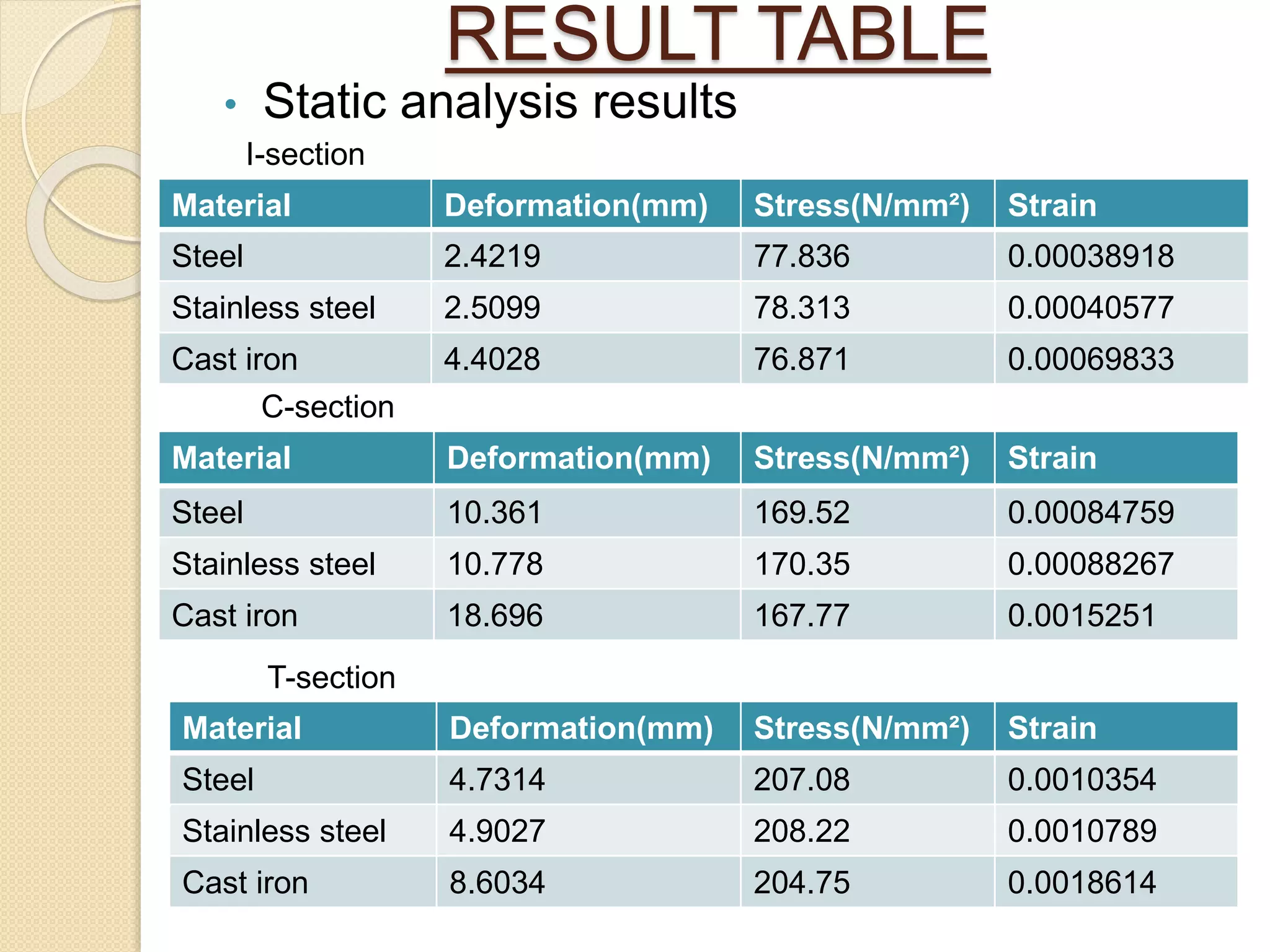


The document details a project analyzing cantilever beams of various cross-sectional shapes (I, C, T) and materials (steel, stainless steel, cast iron) using static and modal analysis in ANSYS. It includes steps for solid modeling, material property assignment, and results comparison, concluding that cast iron performs better in terms of stress and natural frequency for the cantilever beam structure. The analysis reveals that I-section beams exhibit lower deformation and stress values compared to other sections.
Overview of beam properties, material analysis using ANSYS, and project outcomes.
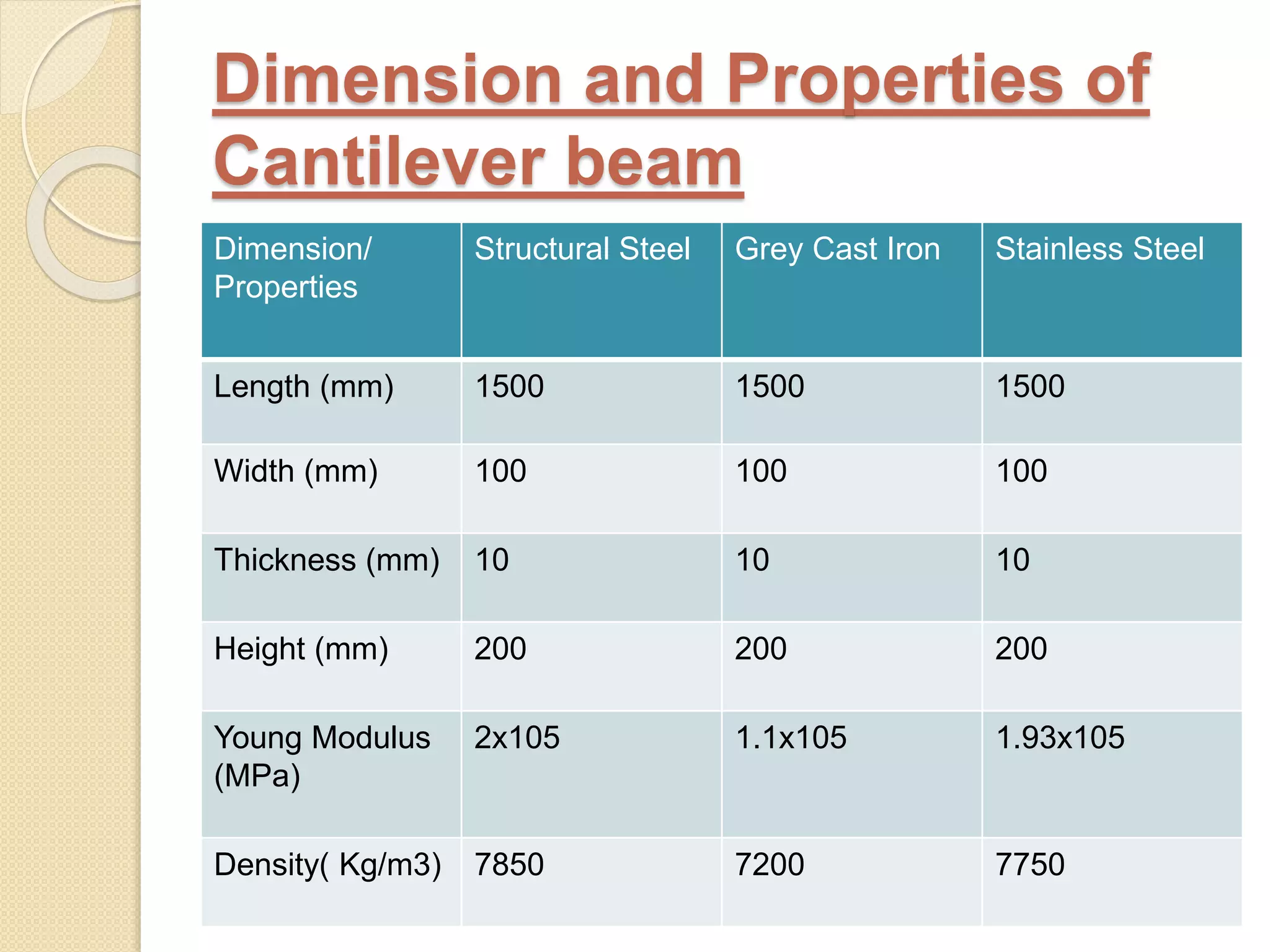
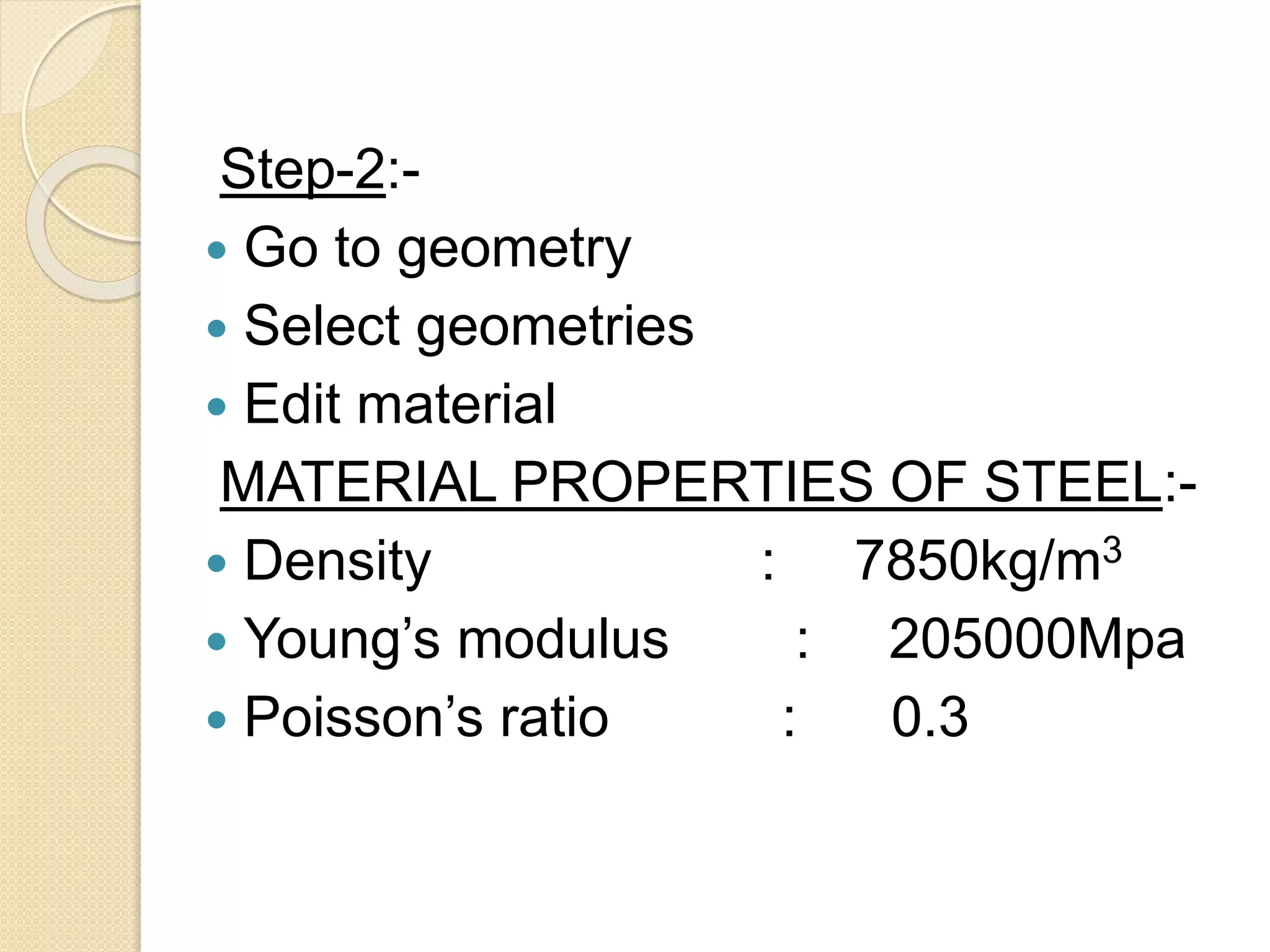
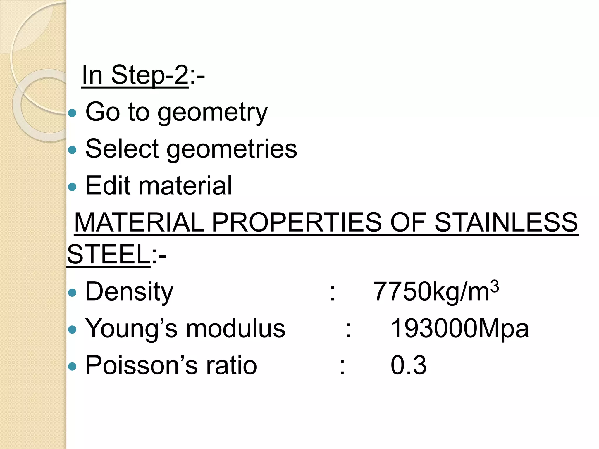
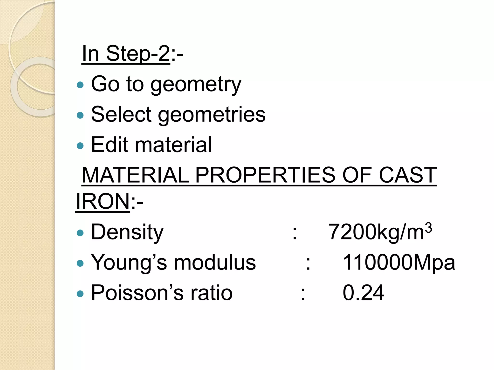
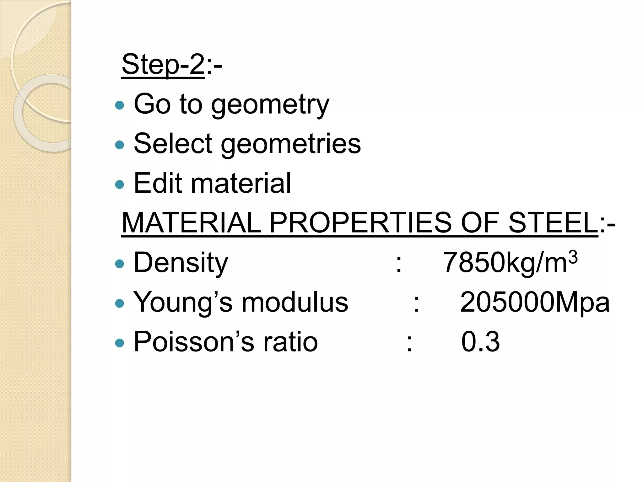
Listing dimensions and material properties for structural steel, grey cast iron, and stainless steel.
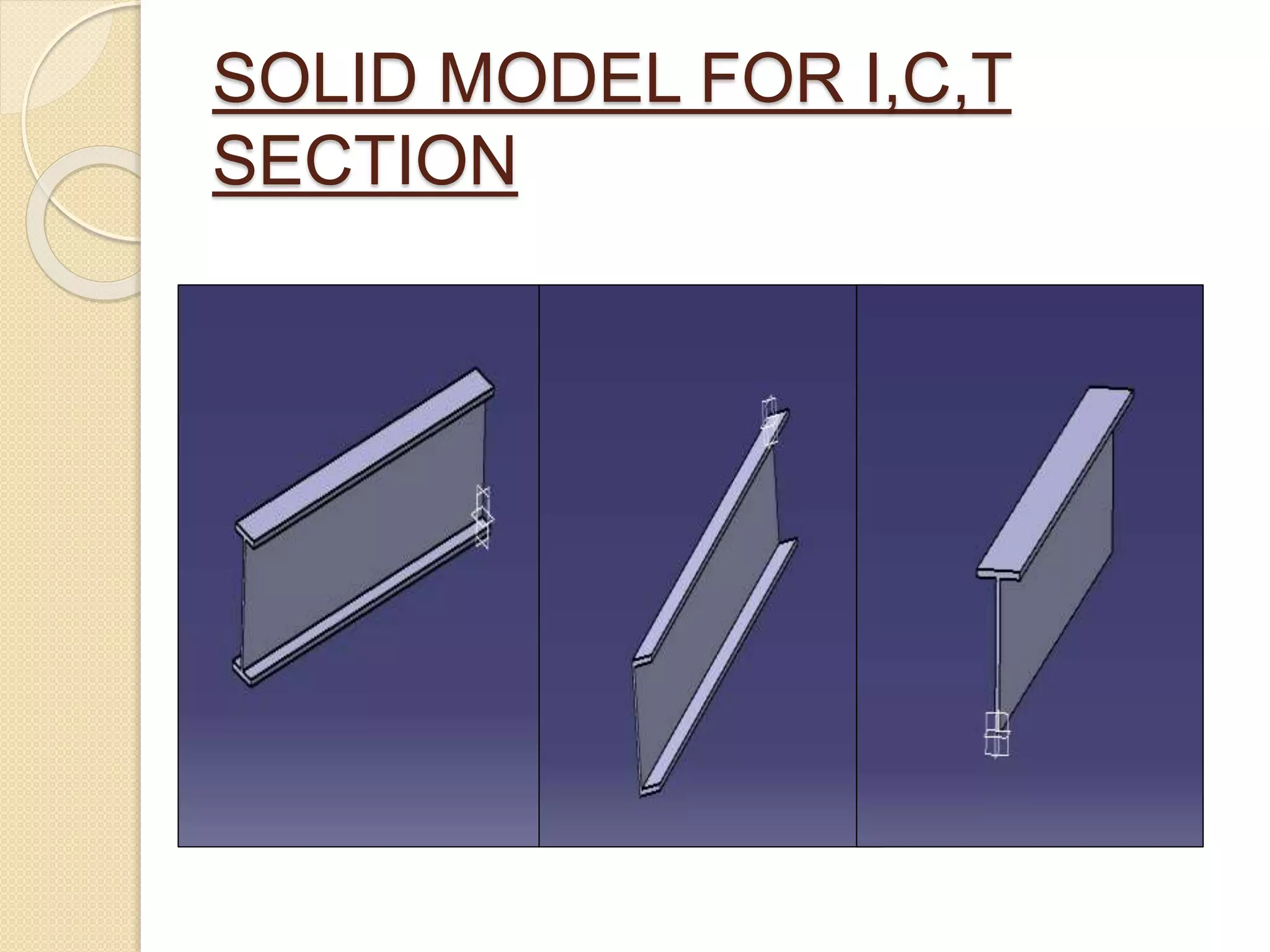
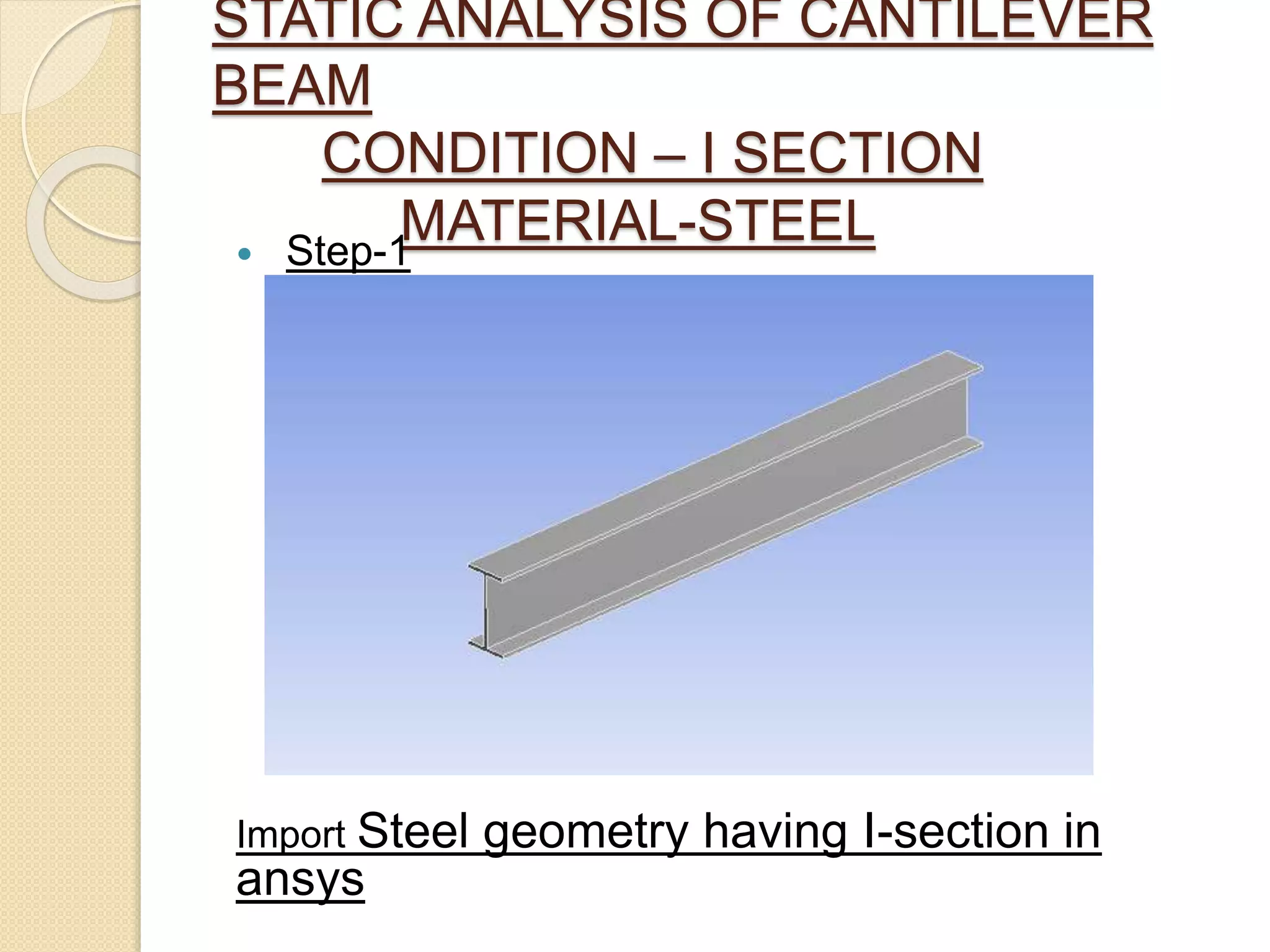
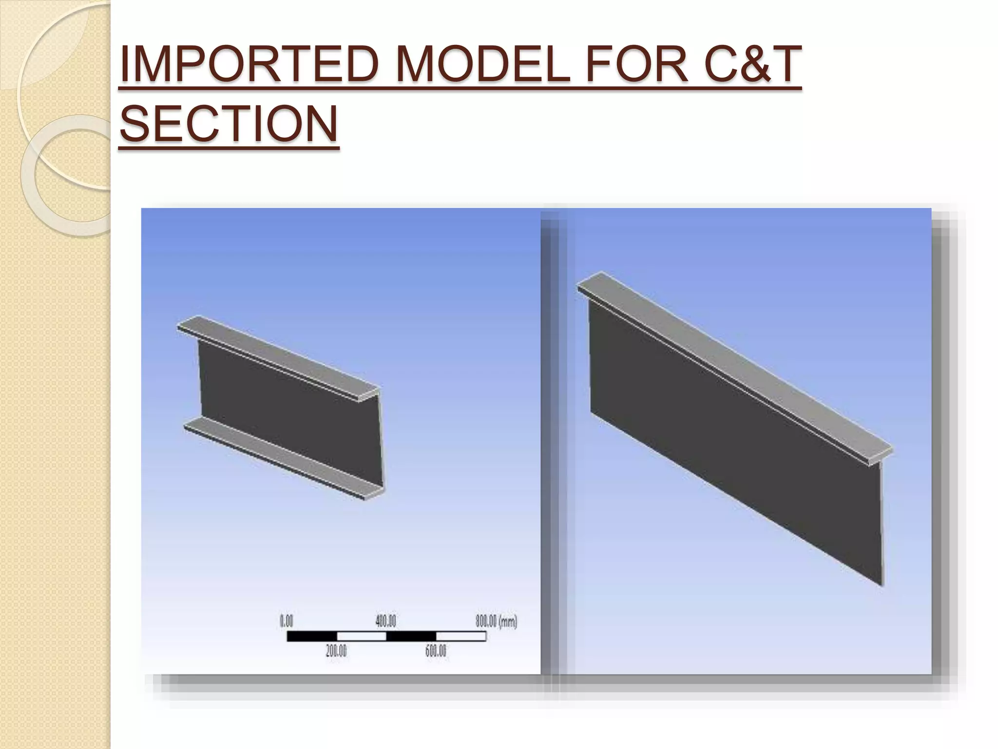
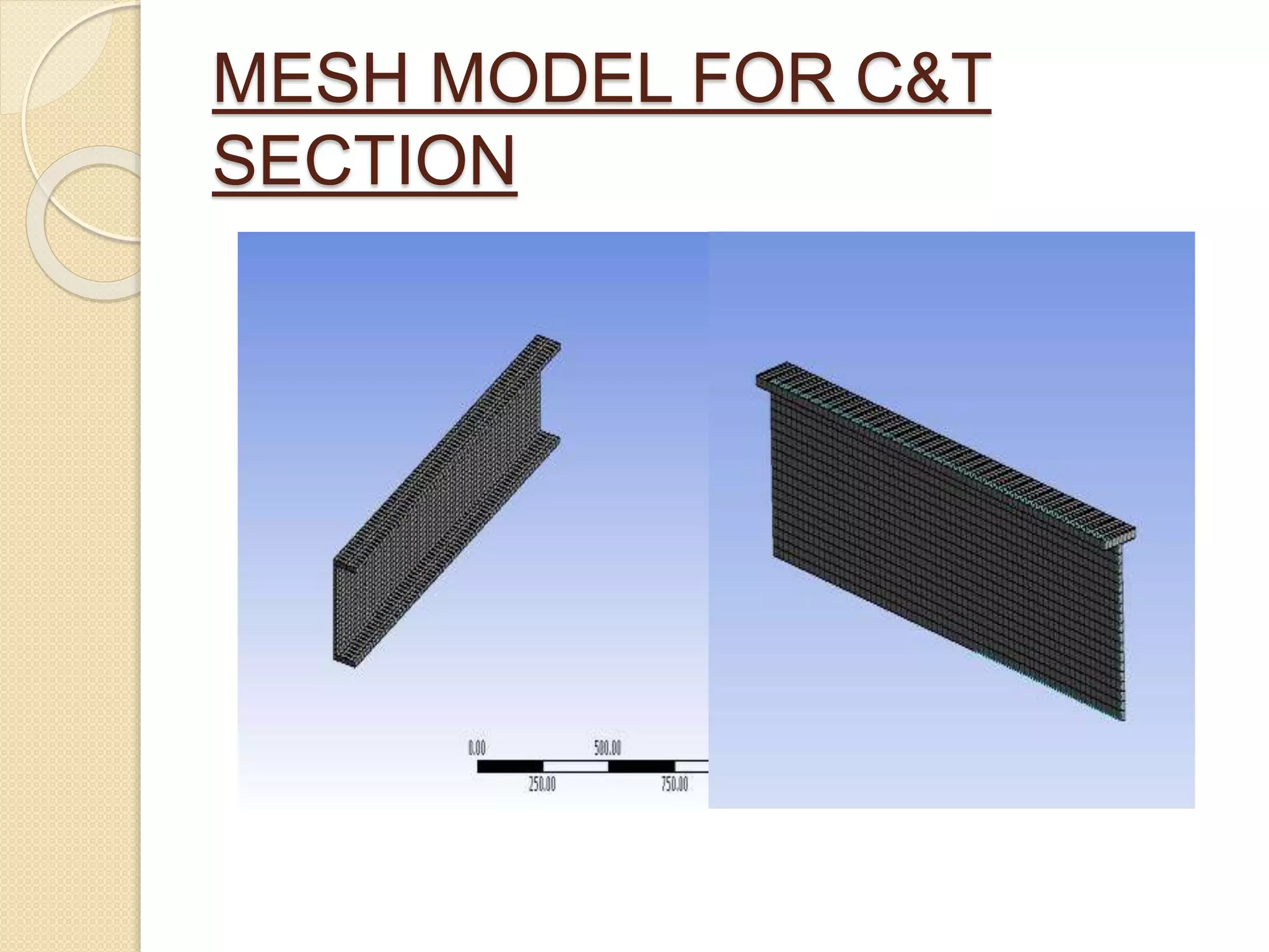
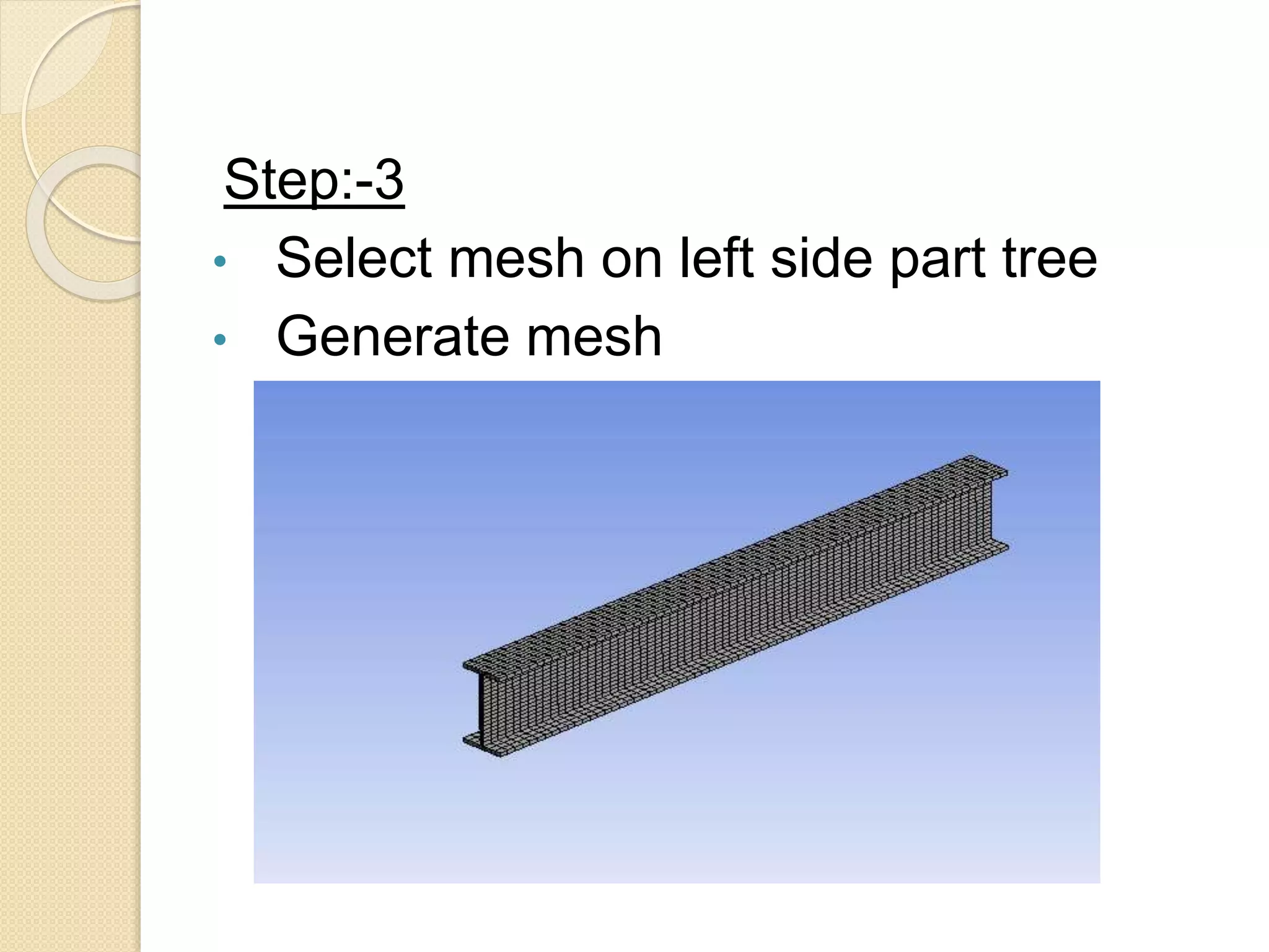
Creating solid models of I, C, & T beam cross sections using Creo, preparing for analysis.
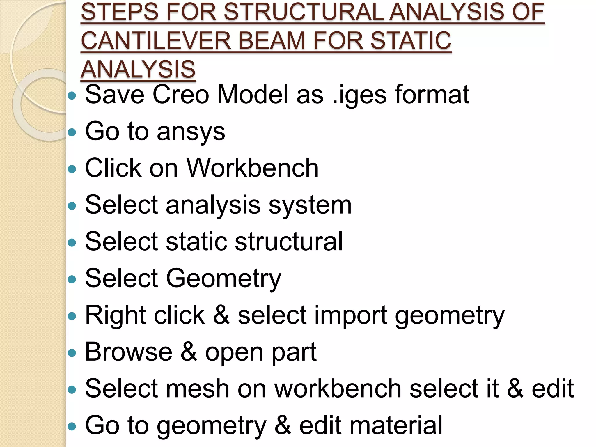
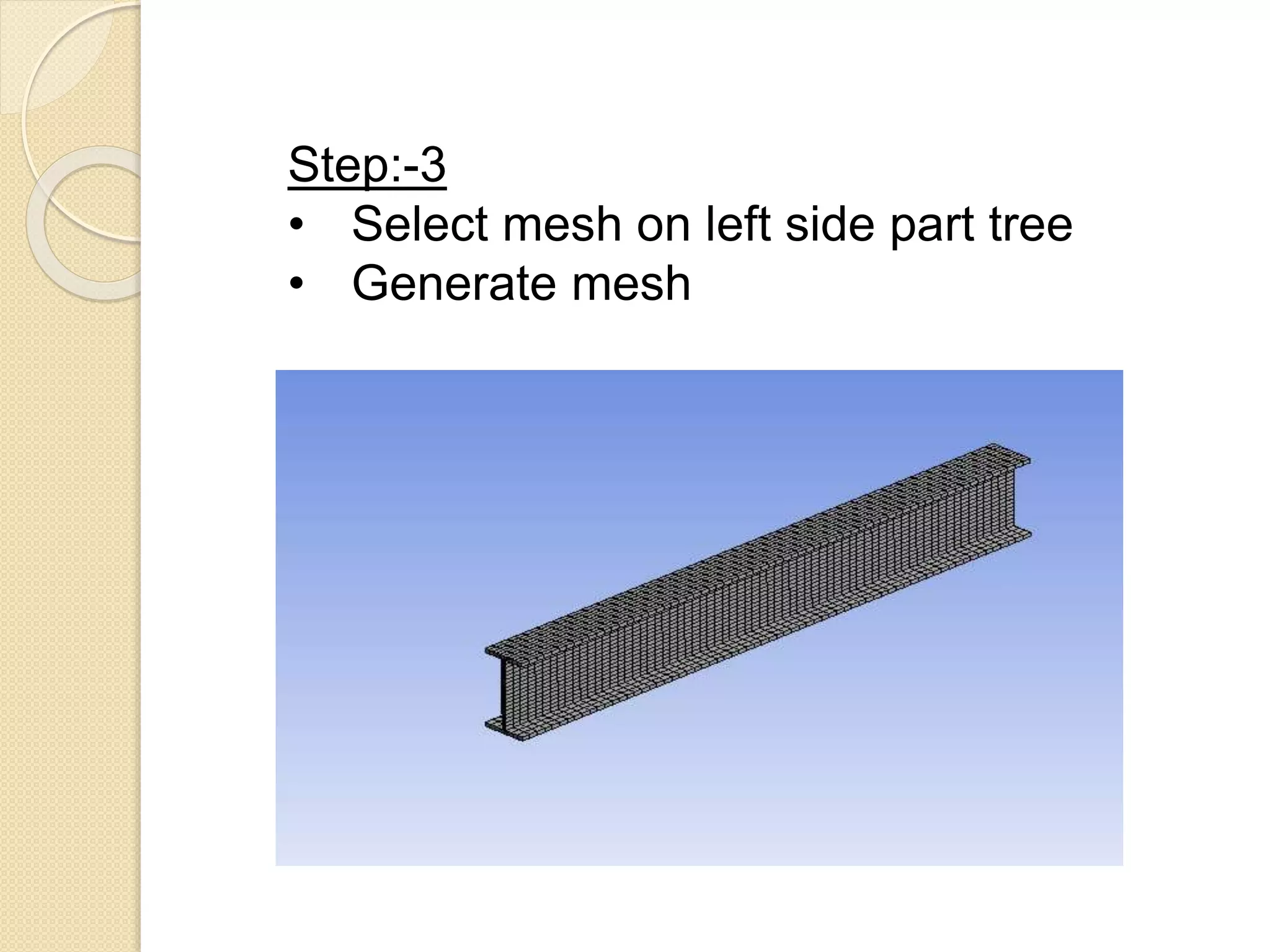
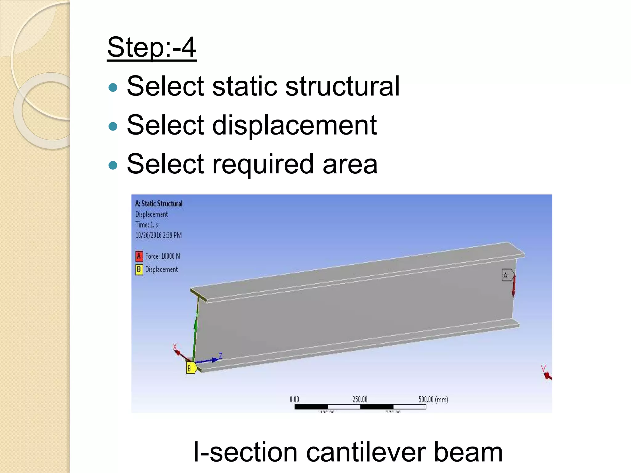
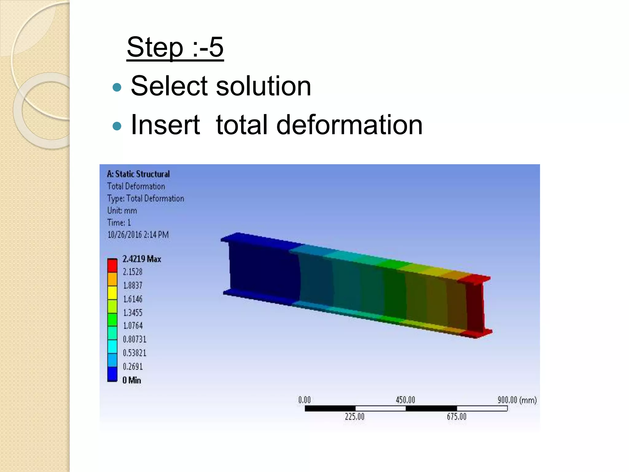
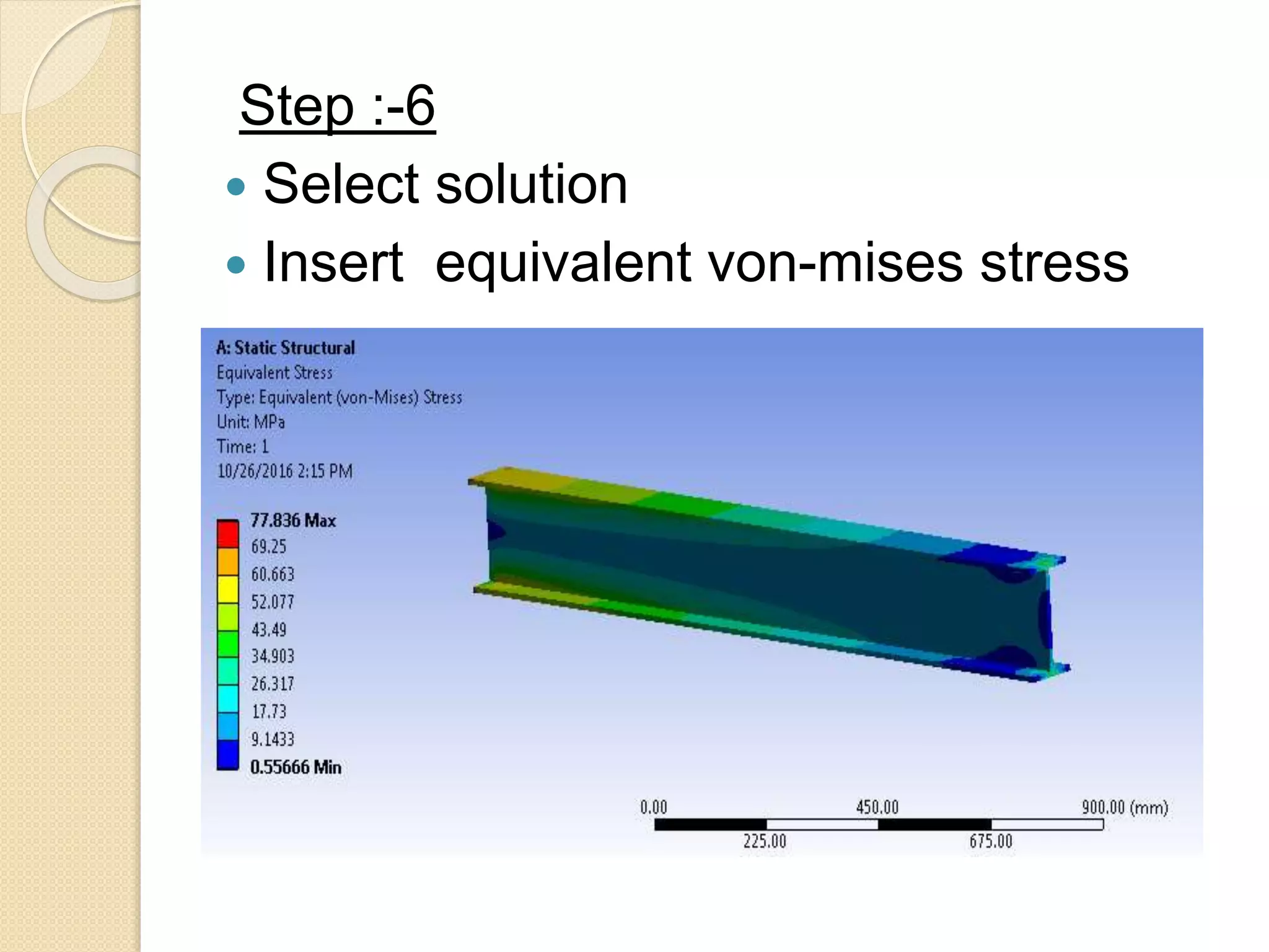
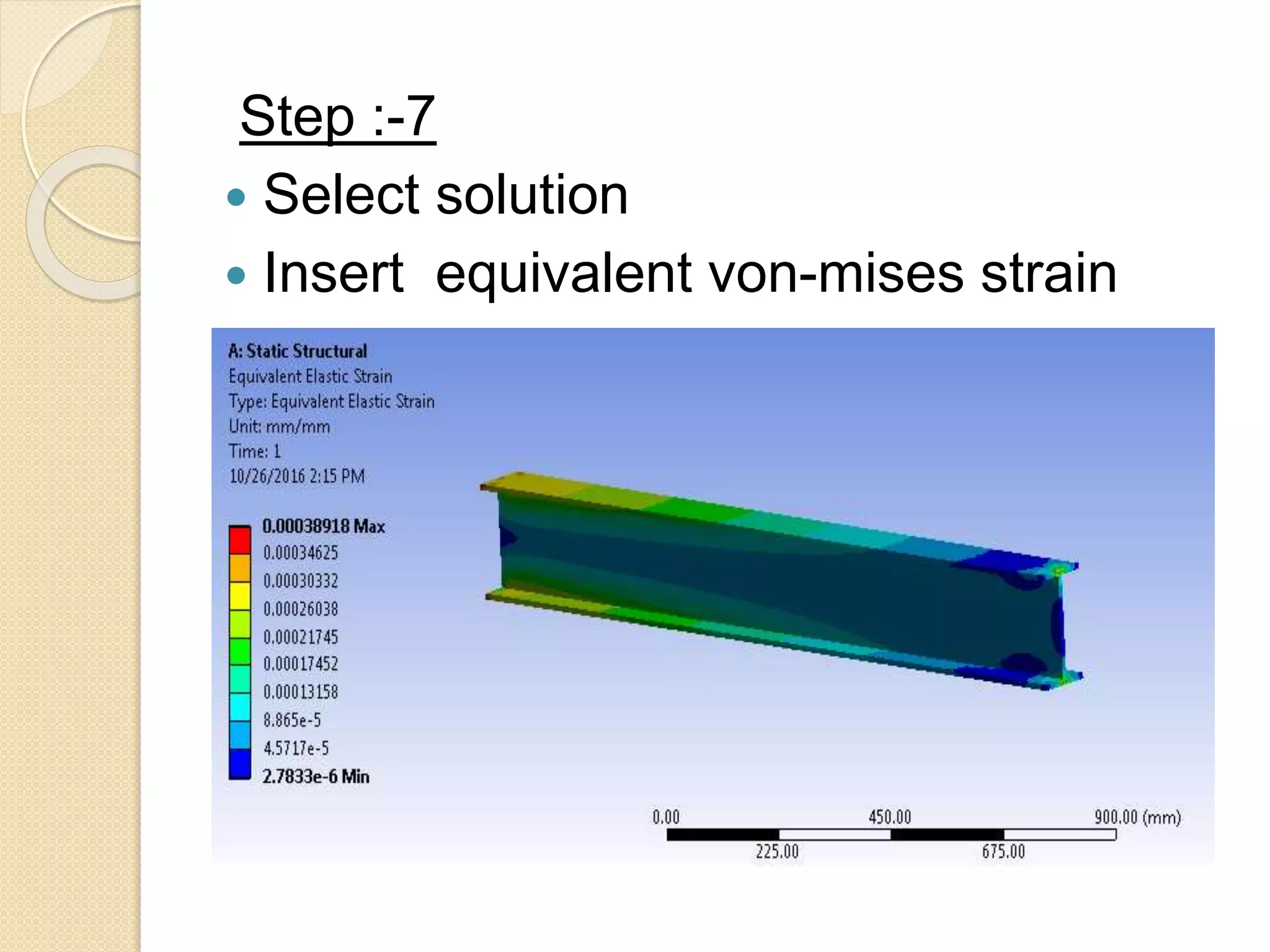
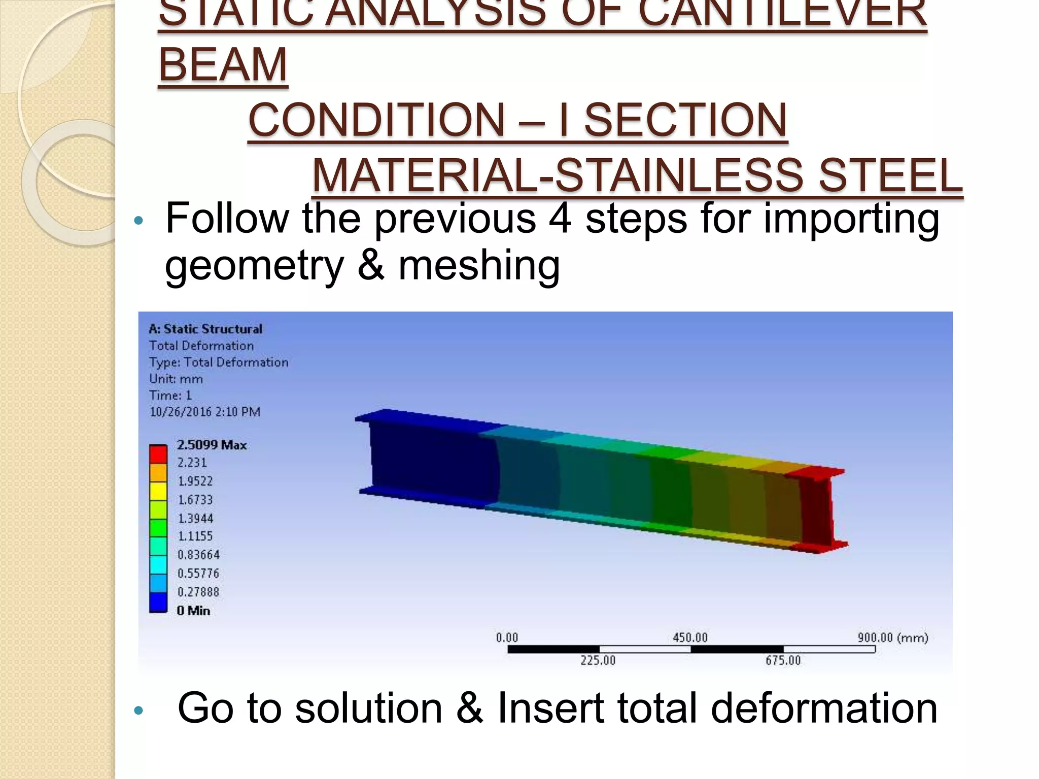
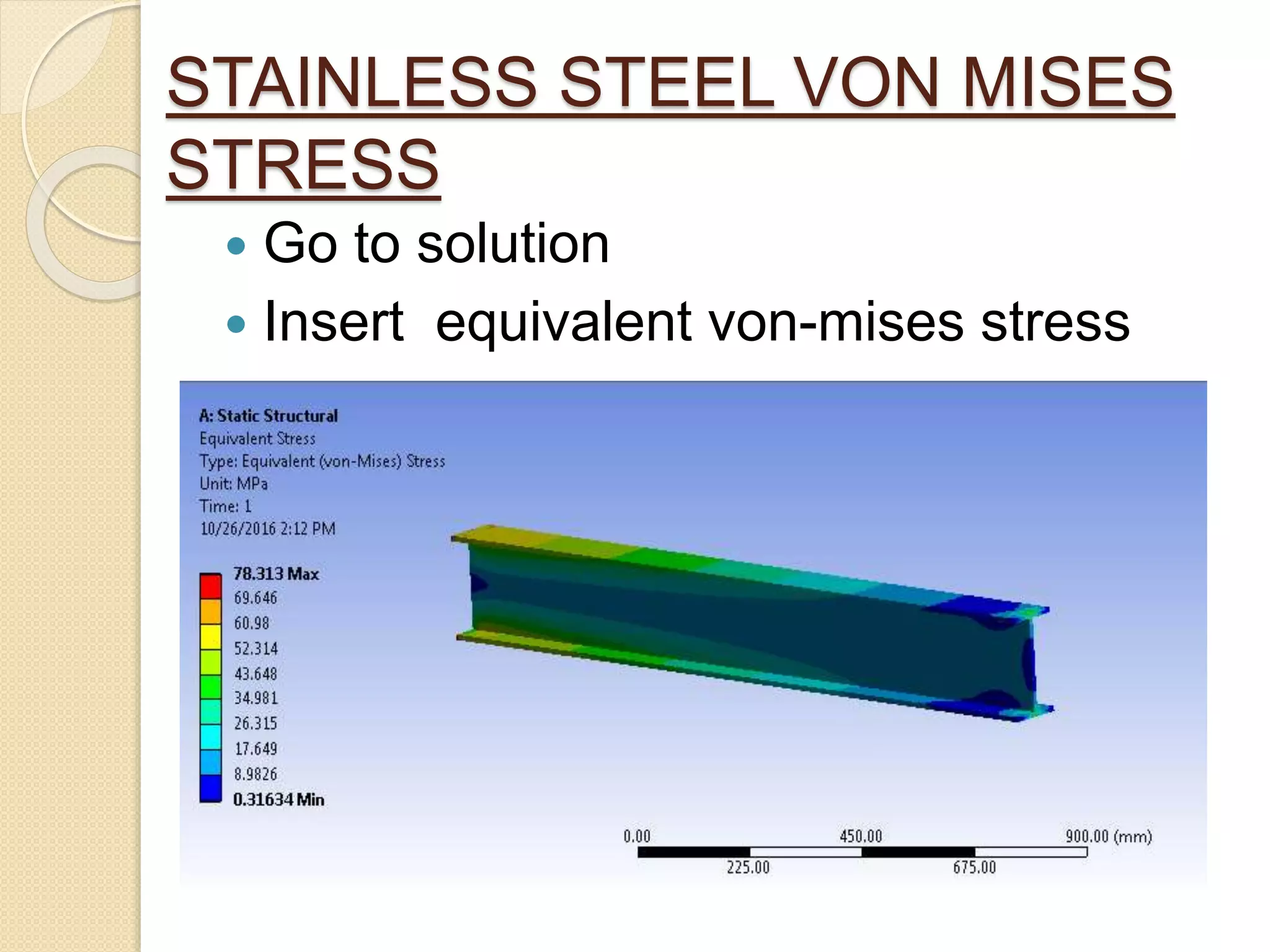
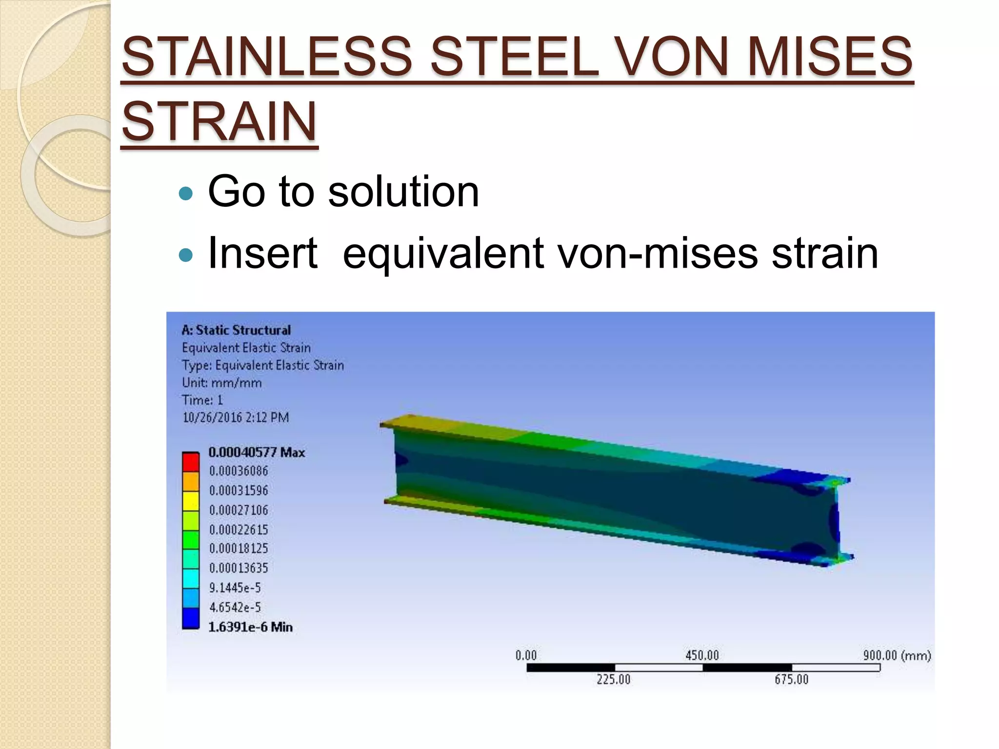
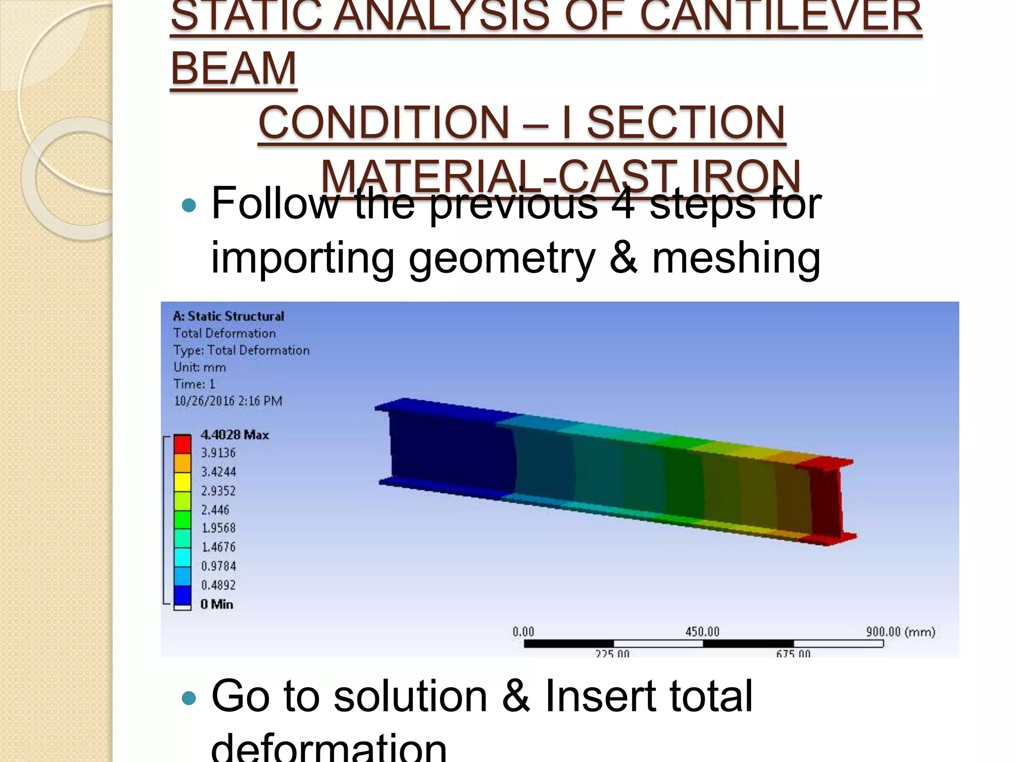
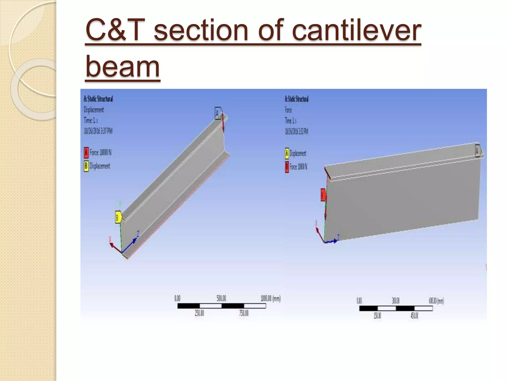
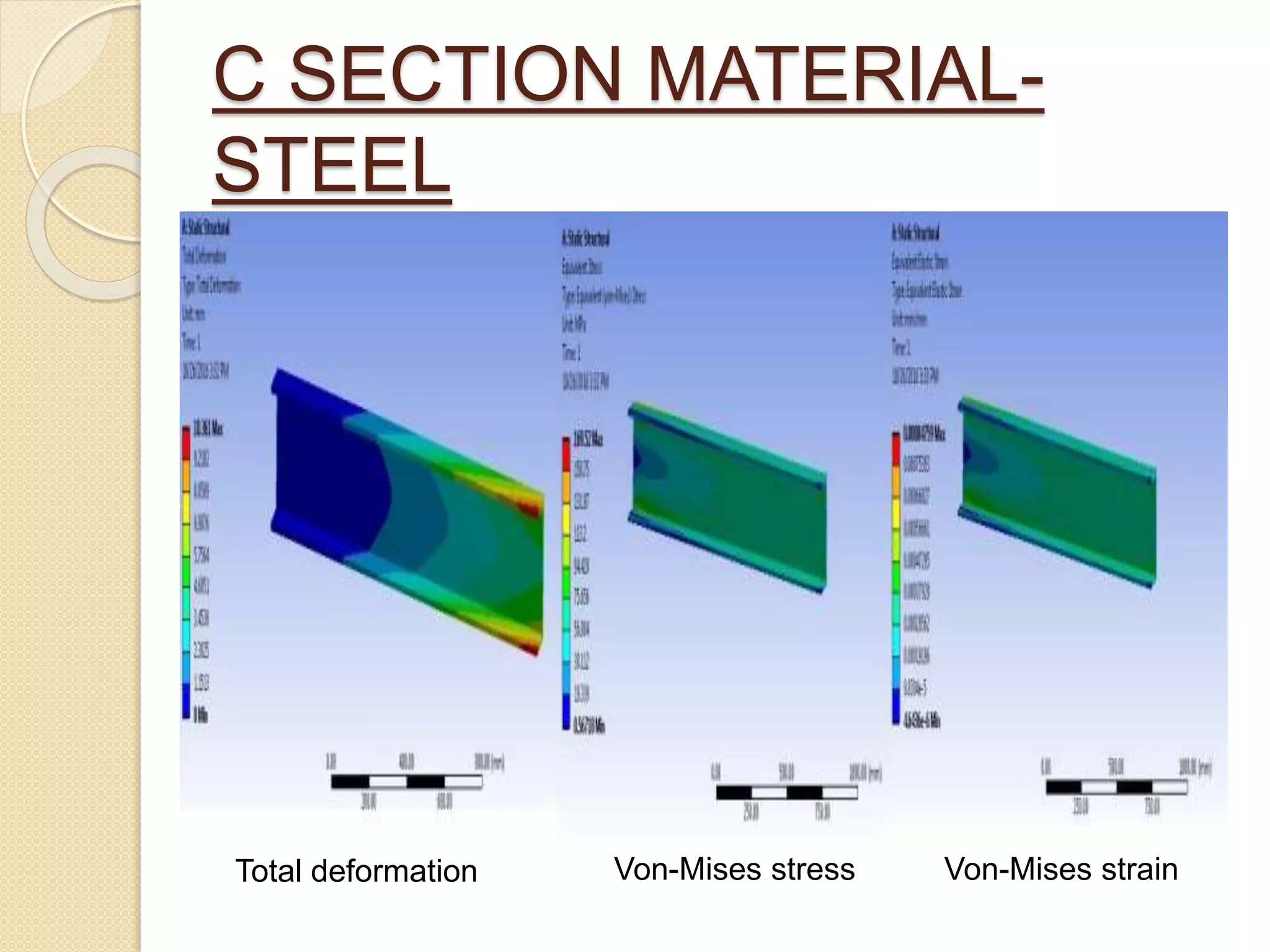
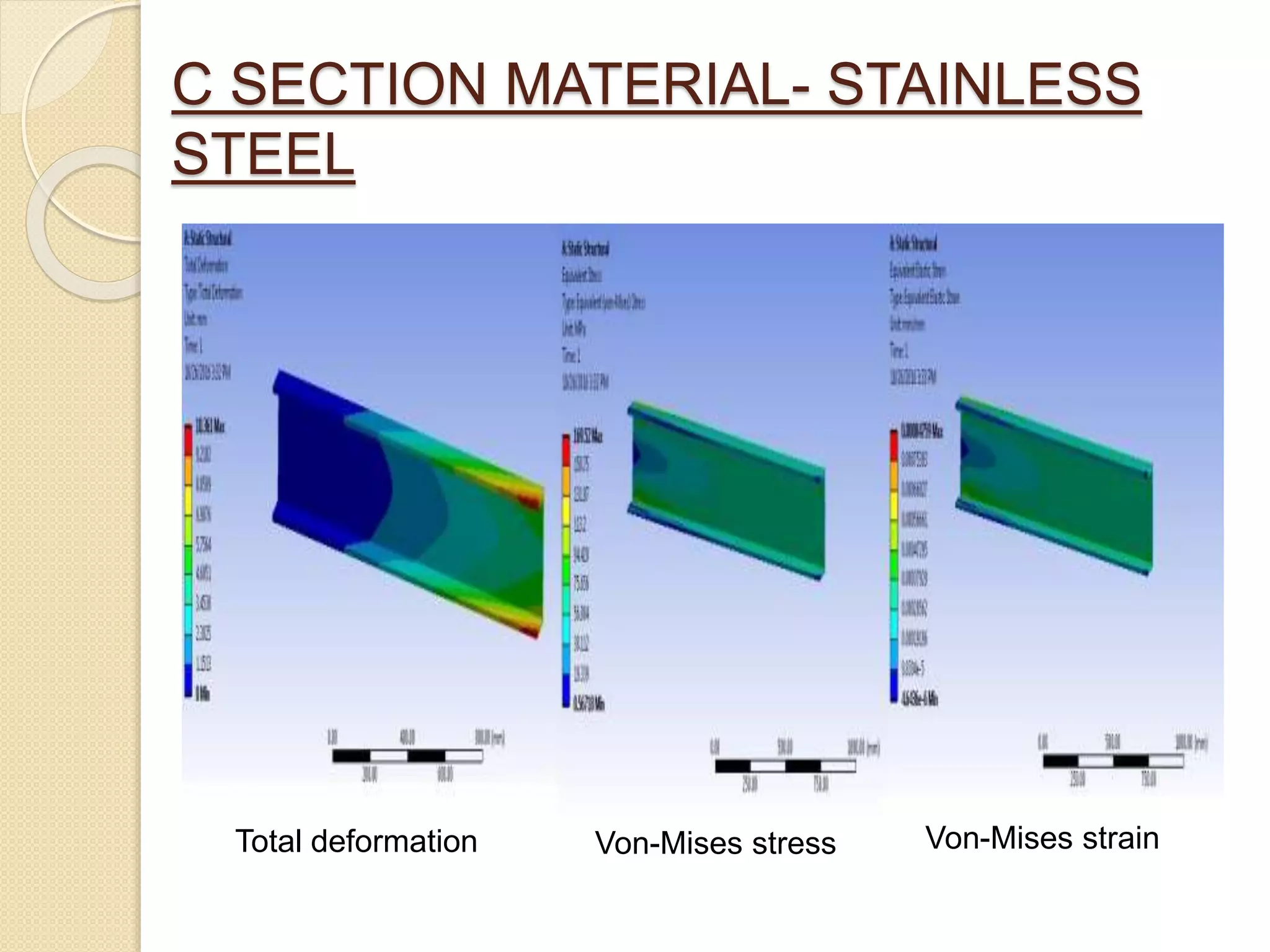
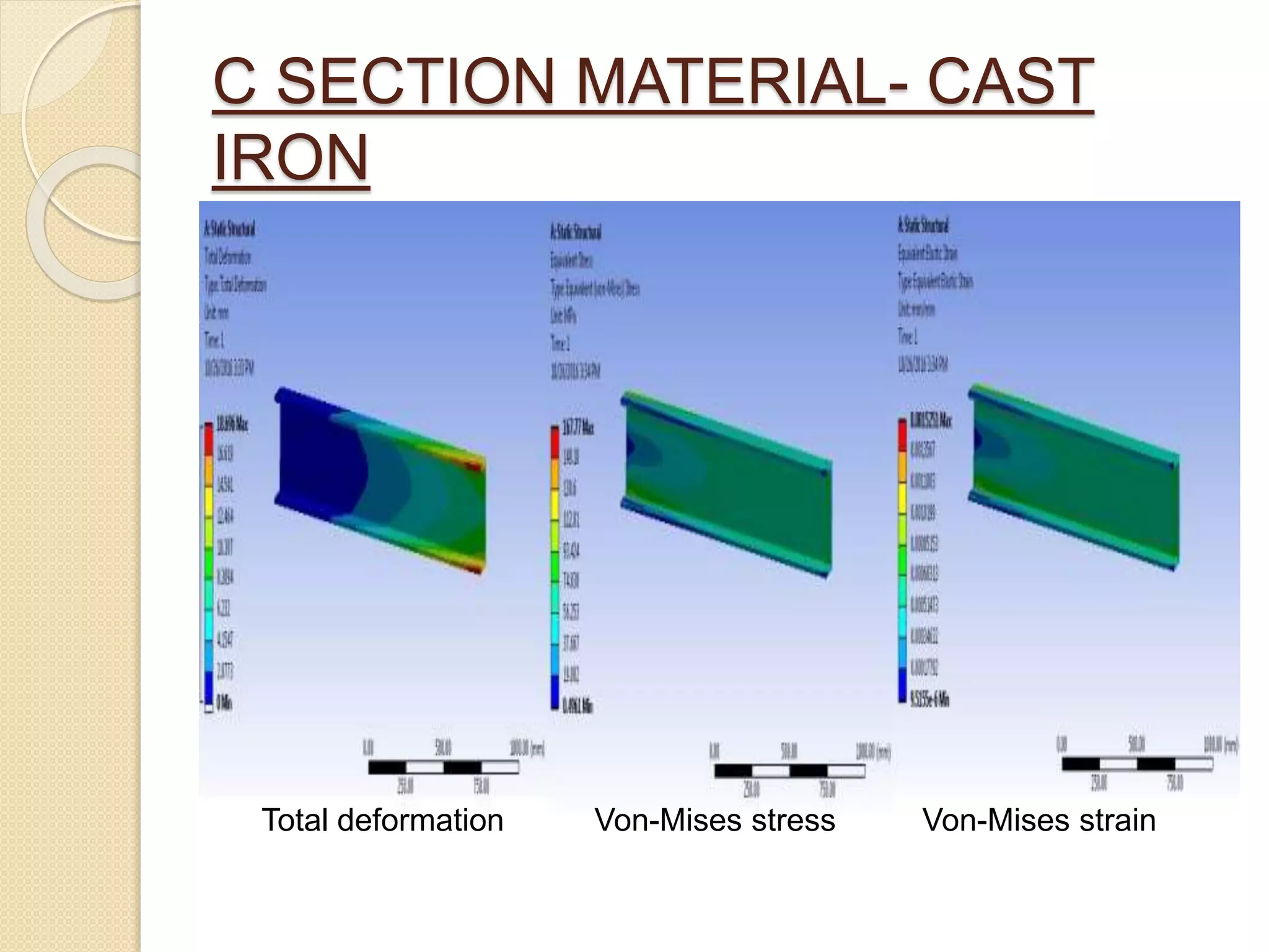
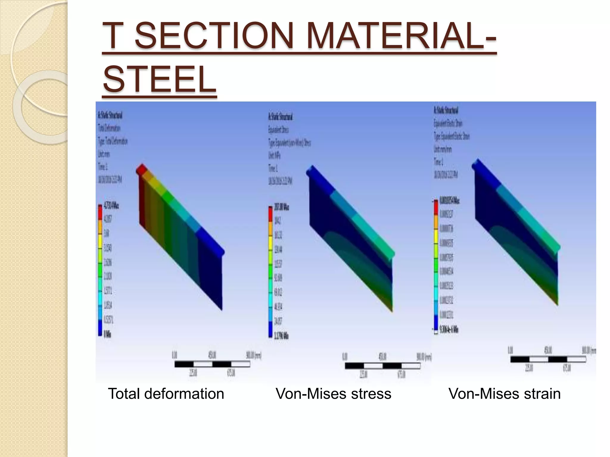
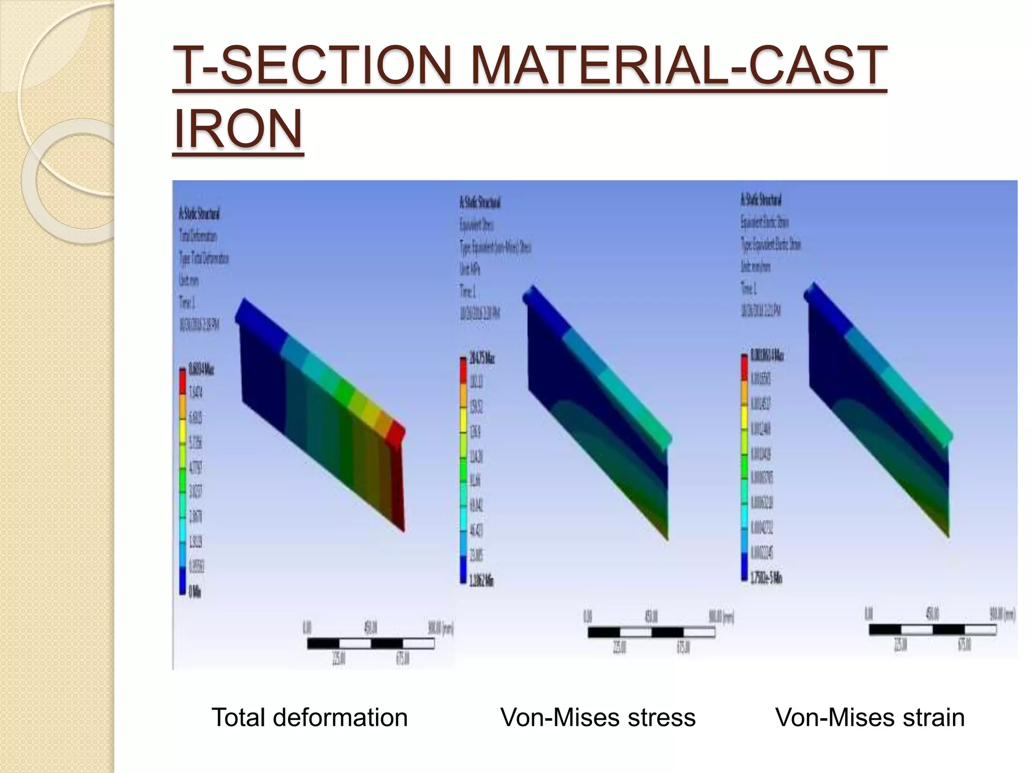
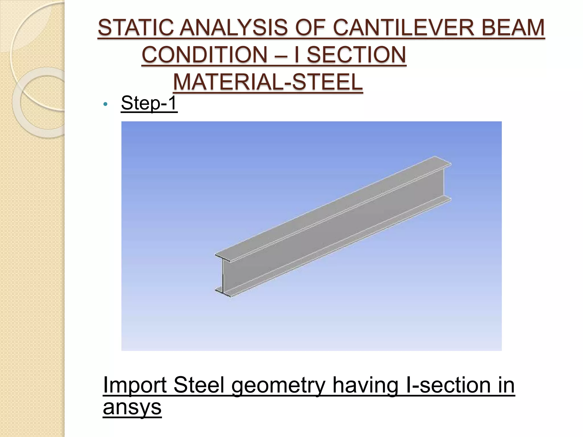
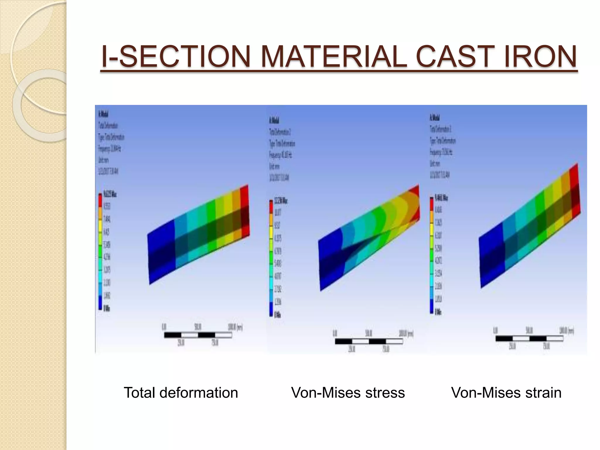
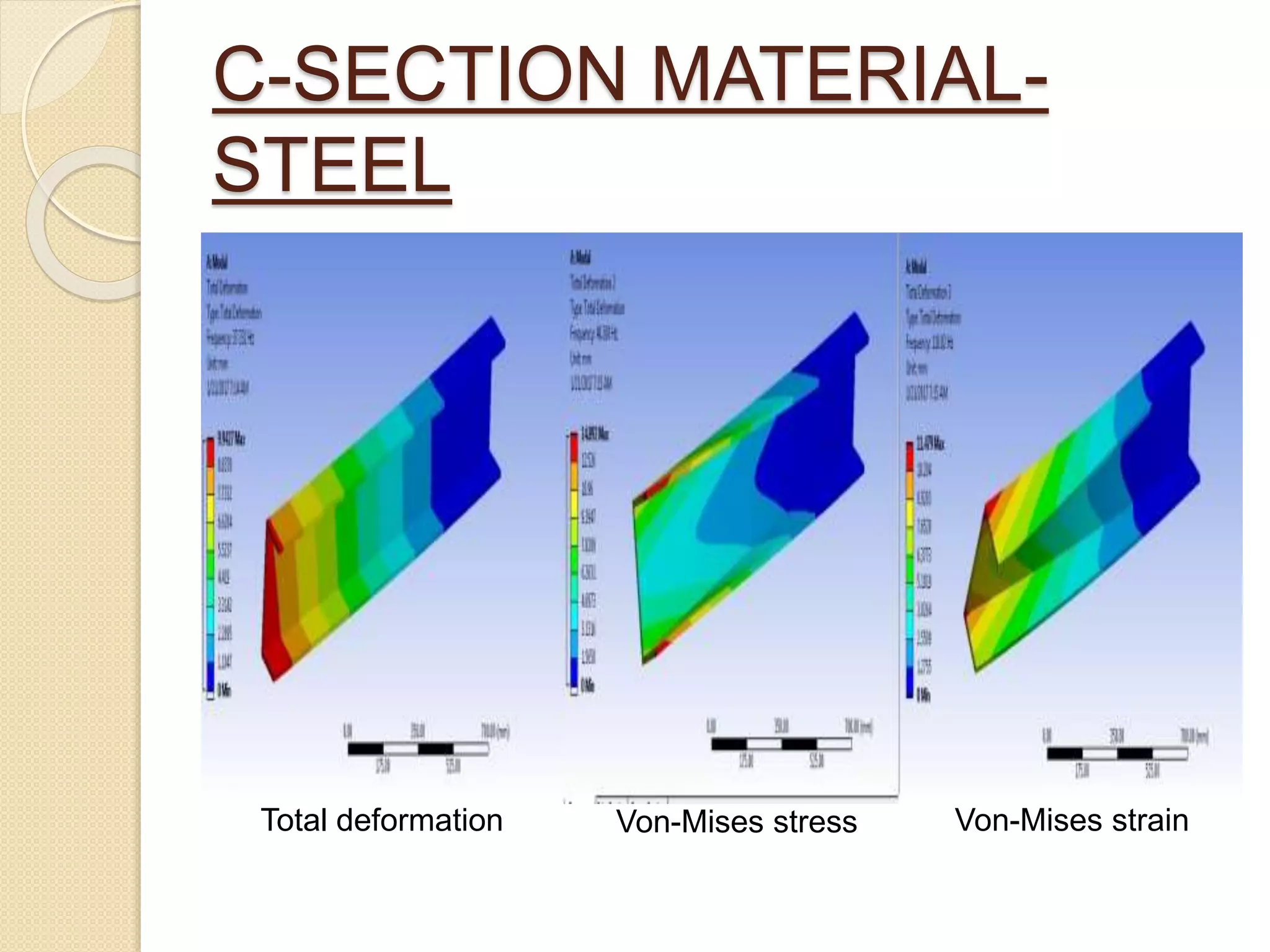
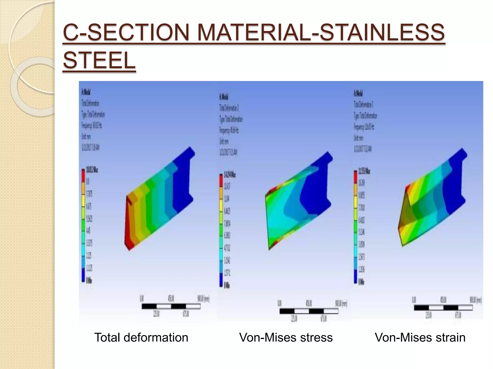
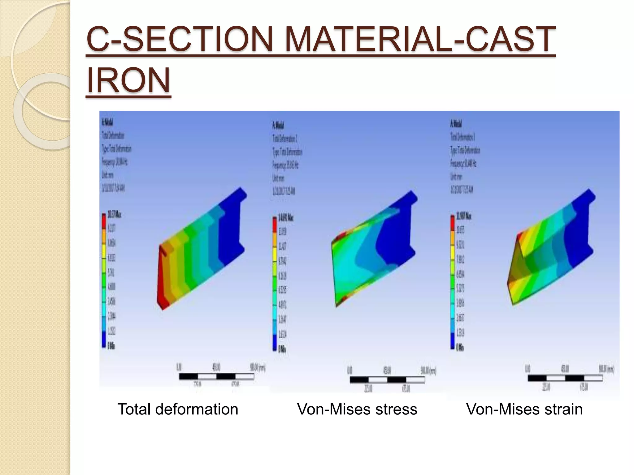
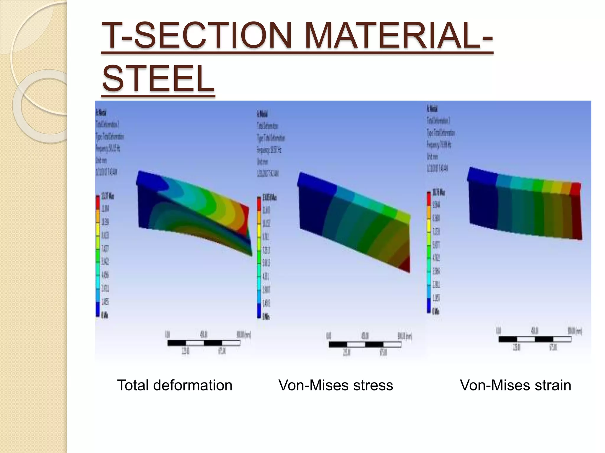
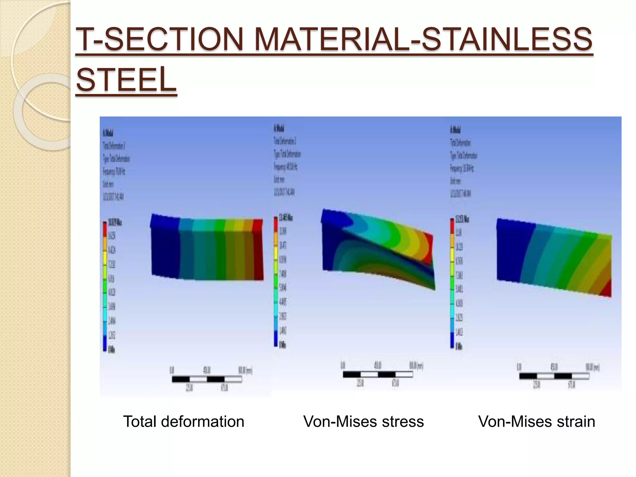
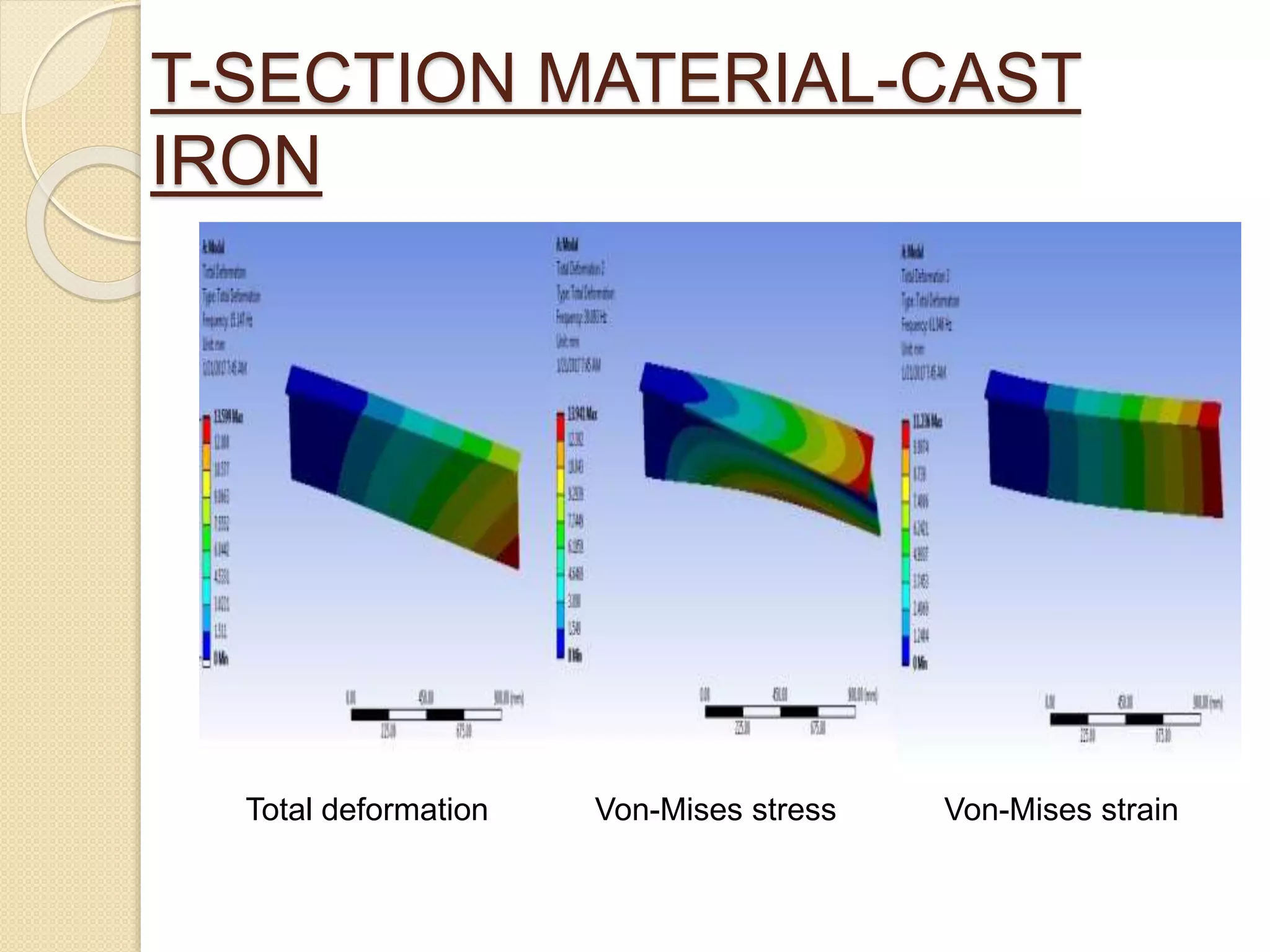
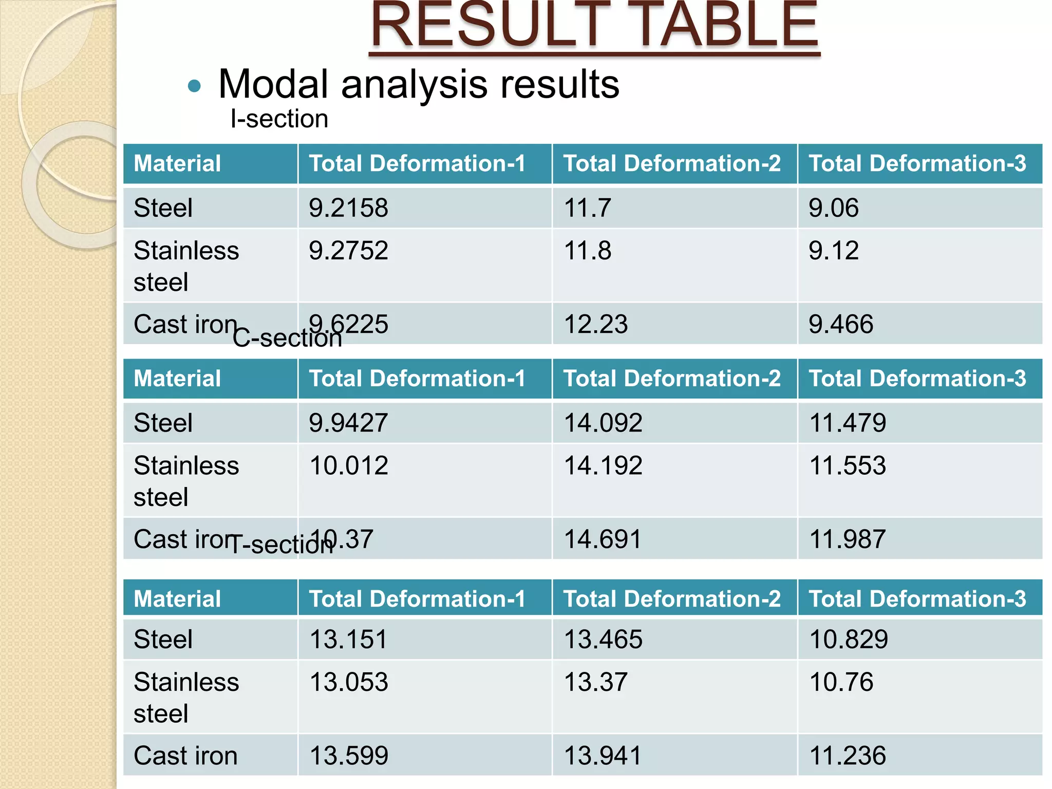
Static structural analysis steps and results for I, C, and T sections using steel, stainless steel, cast iron.
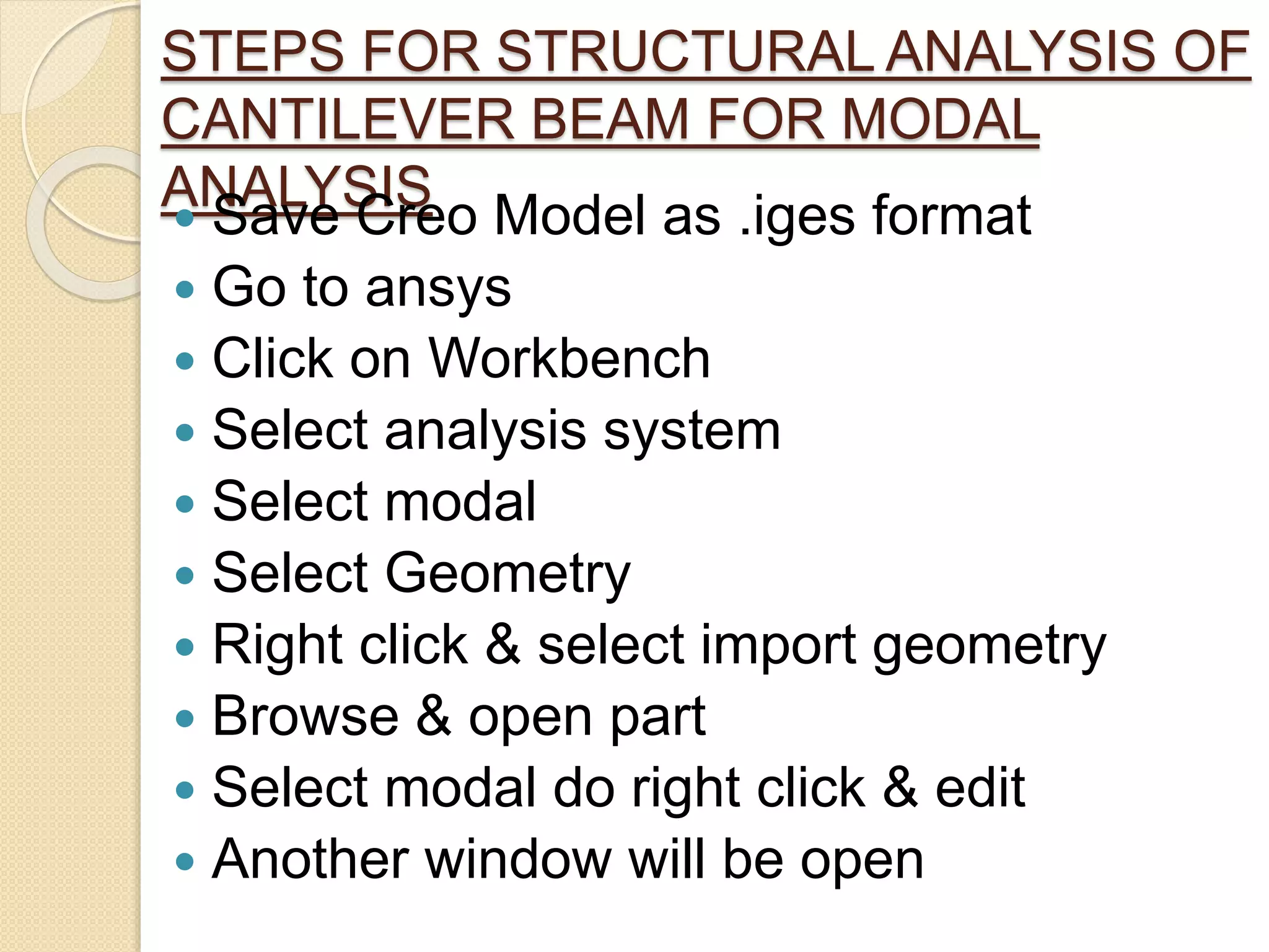
Procedures for performing structural analysis for different beam sections with specified materials.
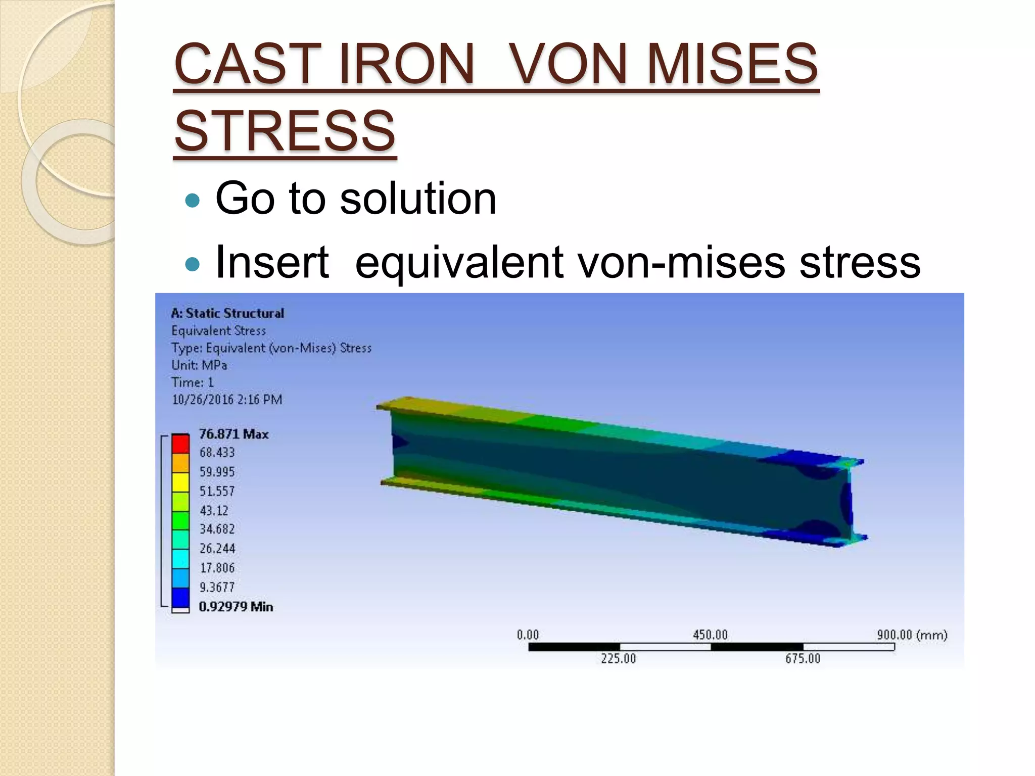
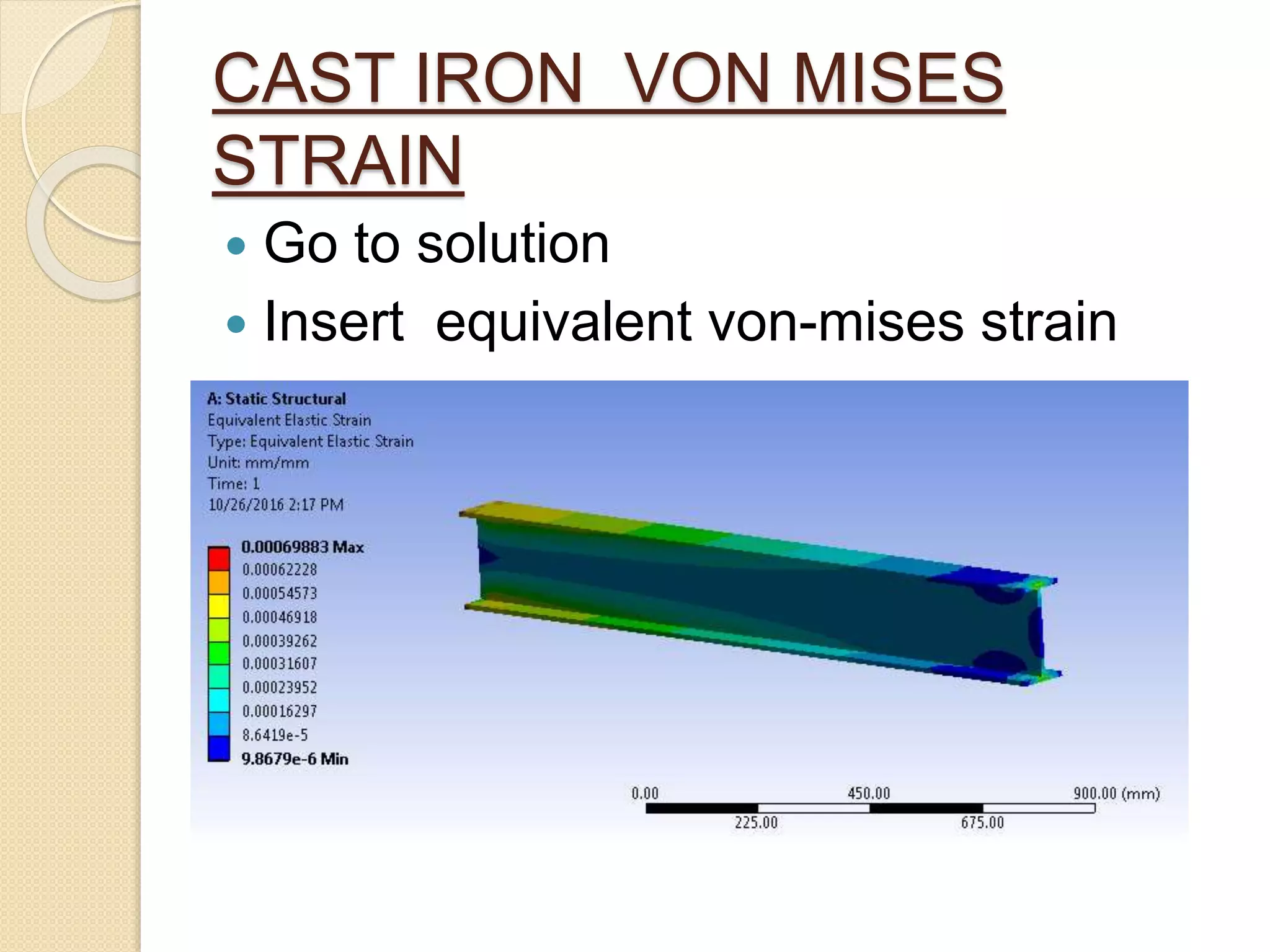
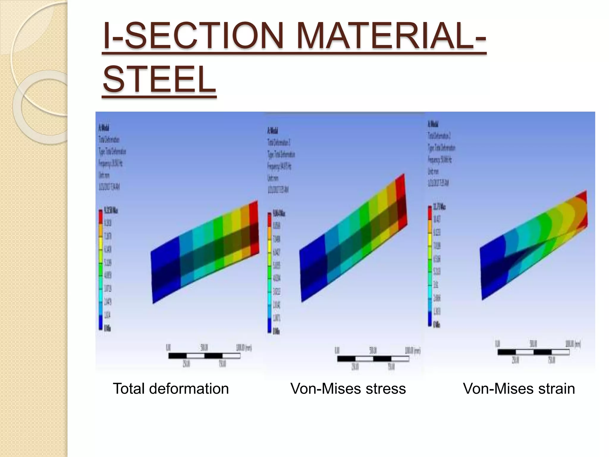
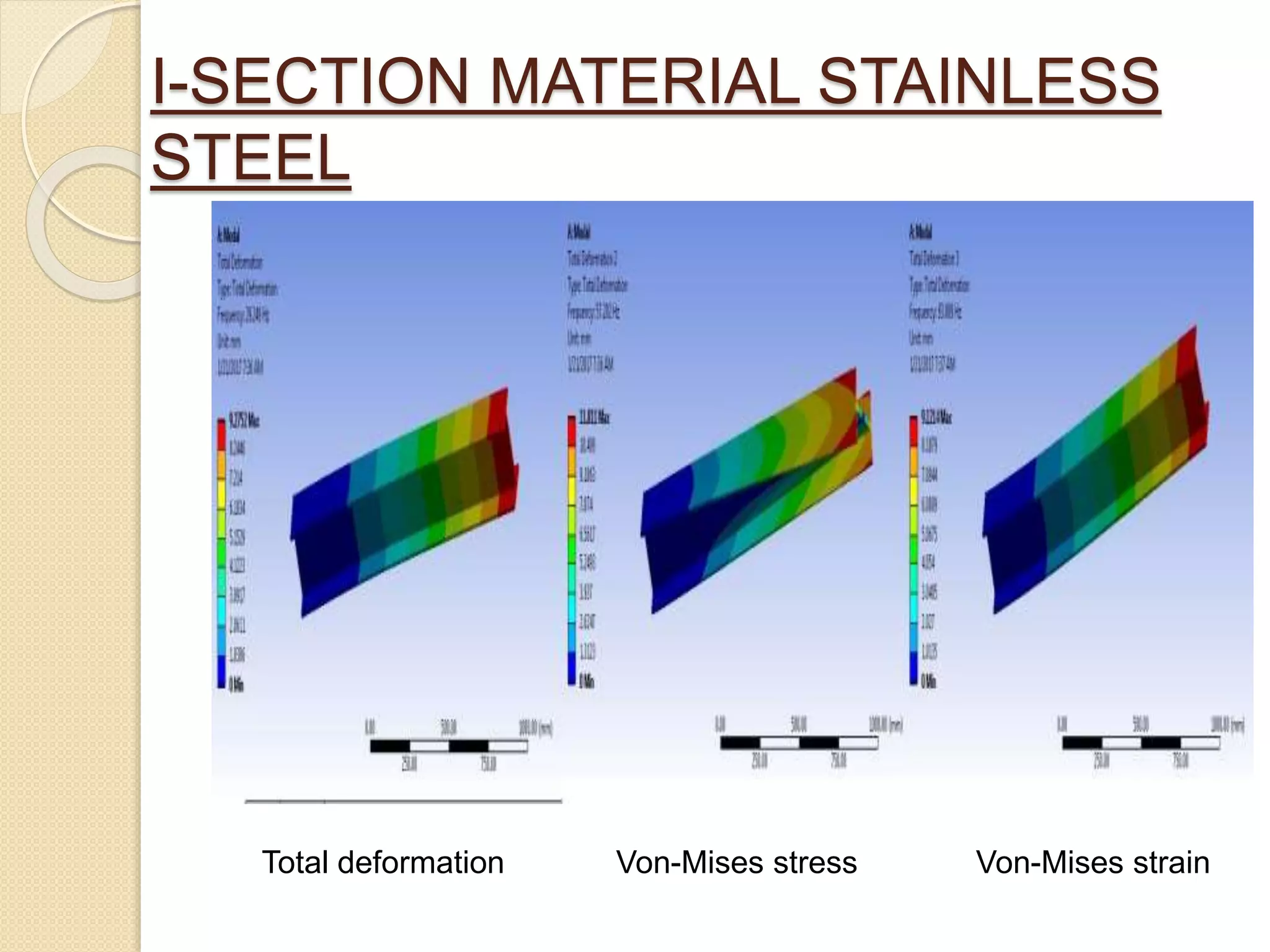
Results comparing total deformation, von-Mises stress, and strain across different materials and sections.
Concluding remarks on the best material for cantilever beams and project findings.
Final thanks and closure to the presentation.


![Modeling and Structural Analysis of a Wing [FSI ANSYS&MATLAB]](https://cdn.slidesharecdn.com/ss_thumbnails/finalreport-191222214155-thumbnail.jpg?width=640&height=640&fit=bounds)