Download to read offline
![IOSR Journal of Computer Engineering (IOSR- JCE)
e-ISSN: 2278-0661,p-ISSN: 2278-8727, Volume 17, Issue 6, Ver. V (Nov – Dec. 2015), PP 36-45
www.iosrjournals.org
DOI: 10.9790/0661-17653645 www.iosrjournals.org 36 | Page
Chaos Encryption and Coding for Image Transmission over
Noisy Channels
Noha Ramadan1
, HossamEldin H. Ahmed2
, Said E. Elkhamy3
, Fathi E. Abd El-
Samie4
1,2,4
(Communication, Faculty of Electronic Engineering/Menofia University, Egypt)
3
(Electrical Engineering, Faculty of Engineering/Alexandria University, Egypt)
Abstract: The security and reliability of image transmission over wireless noisy channels are a big challenge.
Ciphering techniques achieve security, but don't consider the effect of errors occurring during wireless
transmission. Error correction coding techniques must be used with ciphering to improve reliability and
throughput. We propose a combined ciphering and coding scheme based on the modified chaotic Logistic map
with Low Density Parity-check Coding (LDPC) as an error correction coding technique to overcome the
limitations of wireless channels due to the factors that affect transmission such as noise and multipath
propagation. The experimental results show that this combined scheme enhances the performance parameters
such as Peak Signal-to-Noise Ratio (PSNR) and Bit Error Rate (BER)and achieves both security and reliability
in image transmission through the wireless channel
Keywords: Chaos, Filter, Image, LDPC, Logistic map
I. Introduction
Two important issues are needed for the unbounded nature of the wireless communication channel. The
first issue is the security of data transmission, where the unconstrained environment of wireless channel
increases the illegal data access. So, a robust ciphering technique is essential to protect data from attackers. In
the case of traditional image encryption schemes such as Data Encryption Standard (DES) [1] and Advanced
Encryption Standards (AES) [2], wireless communication becomes prohibited due to the long processing time.
Chaos image encryption algorithms have shown better performance in image than the traditional encryption
schemes [3]. Chaotic systems meet the main encryption requirements such as diffusion and confusion [4]. Many
chaotic maps are used for image encryption, such as Logistic and Henon maps [5]. The old Logistic map is one
of the simplest functions of the chaotic system. Mathematically, a Logistic map has the form [6]:
xn=rxn−1(1 − xn−1) (1)
Where xn is a number between zero and one, n is the iteration number, r is the chaotic range, r [0, 4],
and x0 is the initial value.
The second issue of wireless transmission is the reliability. In addition to security considerations, data
must be transmitted correctly without errors. There are many factors that cause errors such as attenuation,
nonlinearities, bandwidth limitations, multipath propagation, and noise [7]. To improve the throughput in noisy
environments, channel coding is performed after ciphering techniques. The basic block diagram of image
transmission is shown in Fig. 1](https://image.slidesharecdn.com/h017653645-160111091341/85/Chaos-Encryption-and-Coding-for-Image-Transmission-over-Noisy-Channels-1-320.jpg)
![IOSR Journal of Computer Engineering (IOSR- JCE)
e-ISSN: 2278-0661,p-ISSN: 2278-8727, Volume 17, Issue 6, Ver. V (Nov – Dec. 2015), PP 36-45
www.iosrjournals.org
DOI: 10.9790/0661-17653645 www.iosrjournals.org 36 | Page
Chaos Encryption and Coding for Image Transmission over
Noisy Channels
Noha Ramadan1
, HossamEldin H. Ahmed2
, Said E. Elkhamy3
, Fathi E. Abd El-
Samie4
1,2,4
(Communication, Faculty of Electronic Engineering/Menofia University, Egypt)
3
(Electrical Engineering, Faculty of Engineering/Alexandria University, Egypt)
Abstract: The security and reliability of image transmission over wireless noisy channels are a big challenge.
Ciphering techniques achieve security, but don't consider the effect of errors occurring during wireless
transmission. Error correction coding techniques must be used with ciphering to improve reliability and
throughput. We propose a combined ciphering and coding scheme based on the modified chaotic Logistic map
with Low Density Parity-check Coding (LDPC) as an error correction coding technique to overcome the
limitations of wireless channels due to the factors that affect transmission such as noise and multipath
propagation. The experimental results show that this combined scheme enhances the performance parameters
such as Peak Signal-to-Noise Ratio (PSNR) and Bit Error Rate (BER)and achieves both security and reliability
in image transmission through the wireless channel
Keywords: Chaos, Filter, Image, LDPC, Logistic map
I. Introduction
Two important issues are needed for the unbounded nature of the wireless communication channel. The
first issue is the security of data transmission, where the unconstrained environment of wireless channel
increases the illegal data access. So, a robust ciphering technique is essential to protect data from attackers. In
the case of traditional image encryption schemes such as Data Encryption Standard (DES) [1] and Advanced
Encryption Standards (AES) [2], wireless communication becomes prohibited due to the long processing time.
Chaos image encryption algorithms have shown better performance in image than the traditional encryption
schemes [3]. Chaotic systems meet the main encryption requirements such as diffusion and confusion [4]. Many
chaotic maps are used for image encryption, such as Logistic and Henon maps [5]. The old Logistic map is one
of the simplest functions of the chaotic system. Mathematically, a Logistic map has the form [6]:
xn=rxn−1(1 − xn−1) (1)
Where xn is a number between zero and one, n is the iteration number, r is the chaotic range, r [0, 4],
and x0 is the initial value.
The second issue of wireless transmission is the reliability. In addition to security considerations, data
must be transmitted correctly without errors. There are many factors that cause errors such as attenuation,
nonlinearities, bandwidth limitations, multipath propagation, and noise [7]. To improve the throughput in noisy
environments, channel coding is performed after ciphering techniques. The basic block diagram of image
transmission is shown in Fig. 1](https://image.slidesharecdn.com/h017653645-160111091341/75/Chaos-Encryption-and-Coding-for-Image-Transmission-over-Noisy-Channels-1-2048.jpg)
![Chaos Encryption and Coding for Image Transmission over Noisy Channels
DOI: 10.9790/0661-17653645 www.iosrjournals.org 37 | Page
Fig. 1 The basic block diagram for image transmission
The Entropy is the expected value of the information contained in a message measured in bits and the
channel capacity is the maximum average amount of information that can be sent per channel. According to
Shannon theory, it is possible to transmit information over the channel reliably (with probability of error → 0) if
and only if the entropy rate (R) is less than or equal to channel capacity R ≤ CX[8]. We can reduce the entropy
of data by adding redundant symbols. This is the key idea of channel coding. We added redundant bits using a
coding algorithm so that we reduce the information of the source and make it able to pass the channel with very
low probability of lost information.
Channel codes are generally divided into block codes such as LDPC codes [9] and convolutional codes
such as Turbo codes [10]. In block codes, the information sequence is broken into blocks of length k and each
block is mapped into channel inputs of length n. This mapping is independent of the previous blocks. In
convolutional codes, there exists a shift register. The information bits enter the shift register at a time and then
the output bits, which are linear combinations of various shift register bits are transmitted over the channel [11].
In our case, we will concentrate on the block codes.
The proposed combined ciphering and coding scheme for image transmission is based on the modified
Logistic map as a ciphering technique for security and LDPC code as a coding technique for reliability.
II. Related Work
In order to achieve information security with a ciphering scheme, an errorless input to the decryption
process is necessary. Error correction codes are necessary to handle a certain amount of errors in the input data,
but these codes are not designed to provide any security of the data. However, there are many cases, in which
both information security and error-correction are needed. Some researchers have studied the combination of
security and the error correction codes in one algorithm to secure transmission of images over wireless networks
[12-14].
In [12], a modified wireless image transmission scheme that combines chaotic encryption based on a
two-dimensional chaotic map and turbo coding technique into one processing step is introduced. In [13],a joint
optimization framework of Rijndael cipher and modulation with the use of Forward Error Correcting (FEC)
codes to protect encrypted packets from bit errors is proposed. In [14], a combination of cryptographic
algorithms and an error correction code is evaluated over an Additive White Gaussian Noise (AWGN) channel.
It is realized by AES-Turbo. AES was chosen for the encryption and decryption process, and turbo codes for
encoding and decoding. According to the general perspective of the system, the turbo encoder block is
embedded in the AES encryption block in the first round after the subbytes block. The remaining steps of the
AES encryption are normal. In the decryption phase, the turbo decoder block is embedded in the AES
decryption block in the last round before subbytes block.
In the proposed combined ciphering and coding scheme, we will use LDPC codes for error correction.
The question now is, Why LDPC? Since 1993, with the invention of turbo codes, researchers have switched
their focus to finding low complexity codes that can approach Shannon channel capacity. Unlike many other
classes of codes, LDPC codes are already equipped with very fast (probabilistic) encoding and decoding
algorithms. New analytic and combinatorial tools make it possible to solve the design problem. This makes
LDPC codes not only attractive from a theoretical point of view, but also perfect for practical applications [15].
The feature of LDPC codes to perform near the Shannon limit of a channel exists only for large block lengths
[16]. For example, there have been simulations that perform within 0.04 dB of the Shannon limit at a Bit Error
Rate (BER) of 10−6 within Shannon limit block length of 107, see Fig. 2 [17].
In addition, LDPC codes have certain advantages over some of the best known codes like turbo codes. Some of
the advantages of LDPC codes may be summarized as follows [18]:
1. They do not have low-weight codewords.
2. They are iteratively decoded with lower complexity.
3. Their error floor occurs at a much lower BER.
4. Their decoding is not trellis based, so they have small delay.
5. They can have very high rates, maximizing information rate (channel usage).](https://image.slidesharecdn.com/h017653645-160111091341/85/Chaos-Encryption-and-Coding-for-Image-Transmission-over-Noisy-Channels-2-320.jpg)
![Chaos Encryption and Coding for Image Transmission over Noisy Channels
DOI: 10.9790/0661-17653645 www.iosrjournals.org 38 | Page
6. They have an excellent error performance; LDPC codes can operate within 0.0045dB away from the
Shannon limit [19], whereas the recently discovered turbo codes can operate within 0.25–0.5 dB away from the
Shannon limit.
Fig. 2 Power efficiency of standard binary channel codes [17].
III. Comparison Between LDPC And Turbo Codes
Now, we will compare between the performance of LDPC and turbo codes in BER to determine the
best for use in the proposed algorithm. We will use the two codes with the parameters shown in Table1.
Table 1. Simulation parameters of the comparison between LDPC and Turbo codes.
½Code Rate
512 bitsBlock length
Binary Phase Shift Keying
(BPSK)
Modulation
Additive White Gaussian
Noise (AWGN)
Channel
From 0 to 4Signal-to-Noise Ratio (SNR) dB
Fig. 3 BER versus SNR of the received Cameraman image with Turbo and LDPC codes.
From the simulation results shown in Fig. 3, it is clear that, theLDPC code achieves a smaller BER than
the turbo codeat the same values of SNR.So that,it is preferable to use the LDPC as an error correction code in
the proposed scheme.
IV. Pefrormance Evaluation Parameters
First, to measure the image quality, we must study some performance evaluation parameters such as the
Peak Signal-to-Noise Ratio (PSNR). PSNR is used as a quality measure between the original and the
reconstructed images. The greater the value of the PSNR, the better the quality of the proposed scheme. The
PSNR for an m x n gray-scale image is defined via the Mean Square Error (MSE) as:
𝑃𝑆𝑁𝑅 = 10𝑙𝑜𝑔10
2552
𝑀𝑆𝐸
(2)
0 0.5 1 1.5 2 2.5 3 3.5
0
0.02
0.04
0.06
0.08
0.1
0.12
0.14
0.16
BER
SNR (dB)
LDPC
Turbo](https://image.slidesharecdn.com/h017653645-160111091341/85/Chaos-Encryption-and-Coding-for-Image-Transmission-over-Noisy-Channels-3-320.jpg)
![Chaos Encryption and Coding for Image Transmission over Noisy Channels
DOI: 10.9790/0661-17653645 www.iosrjournals.org 39 | Page
𝑀𝑆𝐸 =
𝐼1 𝑚, 𝑛 − 𝐼2 𝑚, 𝑛 2
𝑀,𝑁
𝑀 × 𝑁
(3)
where I1represents the original image matrix and I2 represents the image matrix of the reconstructed image.
Bit Error Rate (BER) is another parameter to quantify the reliability. BER determines the reliability of
the entire radio system from “bits in” to “bits out”, including the electronics, antennas and signal path in
between. The BER can be defined as [20]:
BER =
Number of bits in Errors
Total Number of Bits
(4)
V. The Ciphering Scheme
The proposed ciphering scheme is based on the modified chaotic Logistic map developed to increase
the range of r to be from 0 to 13.8. The modified chaotic function is [21]:
xn=rxn−1 1 − xn−1 1 − xn−1 1.2 − 2xn−1 1.2 − 2xn−1 (5)
The bifurcation diagram of the modified Logistic map illustrates xn versus the parameter r and
determines the chaotic range of the map. It is found that when r [6.1, 13.8], the modified Logistic map exhibits
chaotic behavior and depends crucially on the initial conditions as shown in Fig 4.
Fig. 4 Bifurcation diagram of the modified Logistic map.
For a gray-scale image of size M×N, we use a 1-D lexicographically-ordered vector im = { im1 , im2 ,
… , imL }, where L= M×N. Given the initial value of the modified Logistic map x0 =0.02 and the chaotic
parameter r=10, the modified Logistic map uses the plain image to generate the current chaotic number, and
then takes the generated chaotic number as the next input of the chaotic iterations. This process is repeated and
the last output value is used as the initial key. This key is used to encrypt the image. By doing so, the correlation
between the initial key and the plain image is created. The encryption can be described as follows:
Step 1: For n =1,iterate the modified Logistic map using Eq. (5) for only one time to get x1
Step 2:Modify x1 according to the following equation
x1 = mod (x1 + (im1 + 1)/255,1) (6)
Step 3: For n =n+1 return to step 1 until n=L to get xL.
Let the new initial value of the Logistic map be (x0+xL)/2
Step 4: Iterate the modified Logistic map using Eq. (5) for L times with the new initial value. Then, we obtain
the sequence
X = xL+1, xL+2, … , x2L (7)
Step 5: To get the sequence K= {k1, k2,…,KL}:
kn = mod floor xL+n × 105
, 256 (8)
where n = 1, 2, . .](https://image.slidesharecdn.com/h017653645-160111091341/85/Chaos-Encryption-and-Coding-for-Image-Transmission-over-Noisy-Channels-4-320.jpg)
![Chaos Encryption and Coding for Image Transmission over Noisy Channels
DOI: 10.9790/0661-17653645 www.iosrjournals.org 40 | Page
Step 6: Examine the randomness of the sequence kn
H = runstest(kn) (9)
By using the Matlab function (runstest) for randomness,H returns (0) if the sequence is random and (1) if not. In
our case H=0
Step 7: Compute the first cipher pixel by using the value of im1, the constant c and the first key k1
c1 = k1⨁mod im
Step 8: Let n=n+1
Step 9: Compute the nth pixel of the cipher image using the following equation in which the cipher output
feedback is introduced
cn = kn⨁mod imn + imn−1, 256 (11)
Step 10: Repeat step 8 and step 9 until n reaches L, then the cipher image C= {c1, c2,…,cn} is obtained.
VI. Performance And Security Analysis
6.1 Key Space Analysis
In the proposed ciphering algorithm, the secret key depends on three independent variables = {x0, r, c},
x0 and rare double precision numbers, c is a constant integer, c [1, 255]. The numbers for x0 and r are more
than 1014. So, the key space is bigger than (1014x1014x 255). This big key space can resist brute-force attack.
6.2 Statistical Analysis
6.2.1 Histogram
The histogram of the encrypted image for the proposed ciphering algorithm is fairly uniform and
significantly different from that of the original image.
The original image. The histogram of the original image.
The encrypted image The histogram of encrypted image.
Fig. 5 Mandrill image encryption and histogram.
6.2.2 Correlation Of Two Adjacent Pixels
For a plain image, adjacent pixels have a large correlation. For a cipher image, the correlation between
pixels should be as small as possible. To test the correlation between two adjacent pixels in the plain and cipher
images, randomly select s pairs of two adjacent pixels (in vertical, horizontal and diagonal directions) from plain
and cipher images and calculate the correlation coefficient (cc) of each pair [22]. Our experimental results show
very small values of (cc), which means an excellent encryption process, see Table 2.
Table 2. Correlation coefficient of two adjacent pixels in the plain and cipher image.
DiagonalVerticalHorizontalImage
0.81520.85490.8908Mandrill plain image
000.0007Mandrill cipher image (Proposed Algorithm)
6.3 Sensitivity Analysis
6.3.1 Differential Attack Analysis](https://image.slidesharecdn.com/h017653645-160111091341/85/Chaos-Encryption-and-Coding-for-Image-Transmission-over-Noisy-Channels-5-320.jpg)
![Chaos Encryption and Coding for Image Transmission over Noisy Channels
DOI: 10.9790/0661-17653645 www.iosrjournals.org 41 | Page
In general, the encrypted image must be sensitive to small changes in the plain image and secret key. In
order to avoid differential attack, small change in the plain image or secret key should cause a significant change
in the encrypted image. Two parameters were used for differential analysis: Net Pixel Change Rate (NPCR) and
Unified Average Changing Intensity (UACI) [23]. NPCR measures the number of pixels change rate of
encrypted image, while one pixel of plain image is changed. UACI measures the average intensity of the
differences between the plain image and the encrypted image. Table 3 shows the values of NPCR and UACI
between encrypted images with keys (x0, r) and another one with a slightly different key (x0 +Δx0, r+Δr). Our
results show that more than 99% of the pixels in the encrypted image change their gray values, when the key
just changes by 10-10. This means that the proposed algorithm provides high key sensitivity.
Table 3. NPCR and UACI between cipher images.
UACINPCRKeysImage
33.35%99.60%Δx0=10-10
, Δr=0Mandrill
33.35%99.60%Δx0=0, Δr=10-10
6.4 Time Complexity Analysis
The proposed algorithm uses only one round for diffusion operation, and so this reduces the
computational complexity and hence the scheme is practicable in a wireless environment. All the simulation
experiments have been carried out with MATLAB R2007a on windows XP system with a laptop computer
having Intel Core 2 Duo Processor 1.6 GHz, 2 GB RAM, and 150 GB Hard Disk. We used the Mandrill image
with 256 × 256pixels as the plain image. The processing time of the encryption / decryption process is 17.55
seconds.
VII. Low Density Parity Check Code
LDPC is a linear error correcting code used to transmit data over a noisy channel. LDPC transmits
information reliably at rates close to Shannon's limit. LDPC is applied in some modern applications such as
10GBase-T Ethernet, Wi-Fi, WiMAX and Digital Video Broadcasting (DVB).The property of linearity in LDPC
means that the sum of any two codewords is also a codeword. Linear block codes are summarized by their
parameters, where k is the number of information bits and n is the number of code bits. The entropy rate R(code
rate) is equal to k/n. LDPC can be specified by generating a Sparse Parity-Check Matrix H. Sparse means that
the number of ones per column is very small compared to the numbers of zeros.
7.1 Channel Encoder (LDPC)
Given a codeword u and an M x N parity check matrix H, we have [24]:
u.HT=0 (12)
In our case, the code rate is 0.5, the codeword is 512 bits and the H matrix is 512 x 1024. Assume that
the message bits, s, are located at the end of the codeword and the check bits, c, occupy the beginning of the
codeword i.e.
u= [c|s] (13)
Also, let,
H= [A|B] (14)
where A is an M x M matrix and B is an M x N-M matrix
Using Eqs.(13) and (14) in (12), we get
Ac + Bs = 0 (15)
c=A-1Bs (16)
Given the received codeword y, the syndrome vector is
z = y× H (17)
If z = 0, then the received codeword is error-free, else, the value of z is the position of the flipped bit.
For more details about LDPC coding and decoding, readers can refer to [9].
VIII. Noise Reduction Filters
Noise reduction filters are mainly used for smoothing the image such as a conservative smoothing
filter, main filter and median filter. Conservative filter is designed to remove noise spikes and is less effective in
removing Gaussian noise. Mean filter replaces each pixel value in an image with the average value of its
neighbors. The main problems in mean filter are that, for any unrepresentative value of image pixel, it
significantly affects the mean value of all the pixels in its neighborhood. The other problem is the edge blurring.](https://image.slidesharecdn.com/h017653645-160111091341/85/Chaos-Encryption-and-Coding-for-Image-Transmission-over-Noisy-Channels-6-320.jpg)
![Chaos Encryption and Coding for Image Transmission over Noisy Channels
DOI: 10.9790/0661-17653645 www.iosrjournals.org 42 | Page
The best choice of our case is the median filter. Hence, instead of simply replacing the pixel value with the
mean value; it replaces it with the median of neighboring values. The median is calculated by first sorting all the
pixel values from the surrounding neighborhood into numerical order and then replacing the pixel being
considered with the middle pixel value.
IX. The Proposed Scheme
We introduce a new scheme for secure image transmission over noisy channels. It combines ciphering
and coding in one algorithm as follows: at the transmitter, the image is encrypted using a key related to the plain
image. Then; the encrypted image is coded using LDPC code for channel coding. The encrypted encoded image
is modulated using BPSK modulation. The resulting image is then transmitted via AWGN channel. At the
receiver, the reverse process is done such that the image is demodulated, decoded and decrypted to obtain the
reconstructed image, which can be passed through a median filter to reduce the noise as shown in Fig. 6.
Fig. 6 Basic block diagram of the proposed scheme.
X. Simulation Results
The performance of the proposed combined ciphering and coding scheme for image transmission
through AWGN channel has been demonstrated under the simulation parameters shown in Table 4. The result of
the combination of different encryption algorithms and LDPC can be shown in the following subsections.
Table 4 The simulation parameters of the proposed scheme.
Image Cameraman
Ciphering Modified chaotic Logistic map
Coding LDPC
Code Rate = ½
Block length = 512 bits
Modulation BPSK
Channel AWGN
Filter Median filter
SNR (dB) From -5 to 2.75
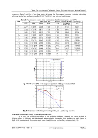
10.1 Peak Signal-To-Noise Ratio
The simulation results show that the proposed combined ciphering and coding scheme has higher
values of PSNR than the combined LDPC with RC6 and with old Logistic map at all values of SNR. The
proposed scheme is very sensitive to the change in the SNR; small changes in SNR achieve large changes in
PSNR. When SNR =2.31 dB, the PSNR of the proposed scheme reaches infinity, and this means that the
reconstructed image is identical to the original image. See Table 5 and Fig. 7.
10.2 Bit Error Rate
To demonstrate the quality of transmission with the proposed scheme, BER should be measured. BER
is computed after decoding with SNR variation. The results show that the BER of the proposed scheme has too
small values at small SNRs, SNR є [0, 2], BER tends to zero at SNR = 2.31dB. This means an error-free
transmission and that the image is reconstructed without distortion. Then, we do not need to retransmit the
image again. Therefore, the proposed combined ciphering and coding scheme increase the throughput of the](https://image.slidesharecdn.com/h017653645-160111091341/85/Chaos-Encryption-and-Coding-for-Image-Transmission-over-Noisy-Channels-7-320.jpg)
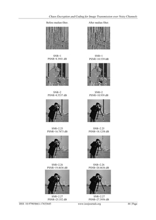
![Chaos Encryption and Coding for Image Transmission over Noisy Channels
DOI: 10.9790/0661-17653645 www.iosrjournals.org 45 | Page
Fig 9 The reconstructed image of the proposed scheme before and after the median filter.
XI. Conclusion
We proposed a scheme for the combination of image encryption and error correction coding. The
proposed scheme combines image encryption based on modified chaotic Logistic map, and error control coding
based on LDPC channel coding, and it uses median filtering. Simulation results show that the proposed scheme
enhanced the performance parameters and achieved both security and reliability of image transmission through
the wireless noisy channel. A comparison between the proposed scheme using the modified Logistic map, using
the old Logistic map and the RC6 showed that the proposed scheme has a higher PSNR and lower BER than the
other schemes. The proposed scheme is suggested for secure image transmission over wireless channels. A
future work is needed to develop an optimization scheme to simulate the real wireless channel such as fading
model and study the security and error correction schemes for wireless image transmission.
References
[1]. National Bureau of Standards, Data Encryption Standard, Federal Information Processing Standards Publication 46, U.S.
Government Printing Office, Washington, DC, 1977.
[2]. Announcing the Advanced Encryption Standard (AES). Federal Information Processing Standards Publication 197.United States
National Institute of Standards and Technology (NIST). November 26, 2001.
[3]. Patidar, V., Pareek, N. K., Sud, K. K., A New Substitution–Diffusion Based Image Cipher Using Chaotic Standard And Logistic
Maps, Commun. Nonlinear Sci. Numer.Simulat., 2009, 14: 3056-3075.
[4]. Zhang LH, Liao XF, Wang XB, An Image Encryption Approach Based On Chaotic Maps, Chaos, Solitons& Fractals, Vol. 24,
2005; Pp. 759–765.
[5]. Chen Wei-bin, Zhang Xin., Image Encryption Algorithm Based on Hénon Chaotic System, 978-1-4244-3986-7/09/© IEEE 2009.
[6]. S. Li, ―Analyses And New Designs Of Digital Chaotic Ciphers, Ph.D. dissertation, Info. And Comm. Eng., Xi’an Jiaotong Univ.,
China, 2007.
[7]. Daniel J. Costello, Jr. and G. David Forney, Jr, Channel Coding: The Road to Channel Capacity, IEEE, Vol. 95, No. 6, June 2007.
[8]. http://en.wikipedia.org/wiki/Information_theory
[9]. Bernhard M. J. Leiner, LDPC Codes- a brief Tutorial, April 8, 2005.
[10]. C. Berrou and A. Glavieux, Near Optimum Error Correcting Coding and Decoding: Turbo Codes, IEEE transactions on
communications Vol.44, No: 10, pp. 1261-1271, 1996.
[11]. Mr. Vishal G. Jadhao, Prof. Prafulla D. Gawande, Performance Analysis of Linear Block Code, Convolution code and
Concatenated code to Study Their Comparative Effectiveness, OSR Journal of Electrical and Electronics Engineering (IOSRJEEE),
SSN: 2278-1676 Volume 1, Issue 1 (May-June 2012), PP 53-61.
[12]. M. A. El-Iskandarani, Saad M. Darwish, Saad M. Abuguba, Combination of 2D Chaotic Encryption and Turbo Coding for Secure
Image Transmission, IJCSNS International Journal of Computer Science and Network Security, vol. 10, No.11, 2010.
[13]. Mohamed A. Haleem, Chetan N. Mathur, R. Chandramouli, and K. P. Subbalakshmi, Opportunistic Encryption: A Trade-off
between Security and Throughput in Wireless Networks, IEEE Transactions on Dependable Computing, 2007.
[14]. Hakan CAM, Volkan OZDURAN, Osman N. UCAN, A Combined Encryption and Error Correction Scheme:AES-Turbo, Journal
of Electrical & Electronics Engineering, vol. 9, No.1, pp. 891-896 , 2009.
[15]. A. Shokrollahi, LDPC Codes: An Introduction, Digital Fountain, Inc., April 2, 2003.
[16]. Bernhard M.J, LDPC Codes – a brief Tutorial,Stud.ID.: 53418L, 2005.
[17]. Matthew Valenti, RohitIyer Seshadri, Turbo and LDPC Codes: Implementation, Simulation, and Standardization, West Virginia
University, 2006.
[18]. Kjetil Fagervik, Arne Larssen, Performance and Complexity Comparison of Low Density Parity Check Codes and Turbo Codes,
Stavanger University Website.
[19]. S.Y. Chung, G. D. Forney, Jr., T. J. Richardson, and R. Urbanke, On The Design of Low-Density Parity-Check Codes Within
0.0045 dB of The Shannon Limit, IEEE Communication. Letter, vol. 5, no. 2, 2001.
[20]. Mona F. M. Morse, HossamEldin H. Ahmed, Fathi, E. Abd El-samie, Ayman H. Abed El-aziem Combination of Hybrid Chaotic
Encryption and LDPC for Secure Transmission of Images over Wireless Networks, IJIGSP Vol. 6, No. 12, November 2014
[21]. Noha Ramadan, HossamEldin H. Ahmed and Said E. Alkhemy, Fathi, E. Abd El-Samie, Hybrid Ciphering System of Image based
on Fractional Fourier Transform and Two Chaotic Maps, International Journal of Computer Applications (IJCA) June 2014
[22]. A. Kanso and M. Ghebleh, A novel image encryption algorithm based on a 3D chaotic map, Communications in Nonlinear Science
and Numerical Simulation, vol. 17, no. 7, pp. 2943–2959, 2012.
[23]. G. Alvarez and S. Li, Some basic cryptographic requirements for chaos-based cryptosystems, International Journal of Bifurcation
and Chaos, vol. 16, no. 8, pp. 2129– 2151, 2006.
[24]. A Tutorial on Low Density Parity-Check Codes, Tuan Ta, The University of Texas at Austin, Internet resources.
SNR=2.31
PSNR=Inf
SNR=2.31
PSNR= Inf](https://image.slidesharecdn.com/h017653645-160111091341/85/Chaos-Encryption-and-Coding-for-Image-Transmission-over-Noisy-Channels-10-320.jpg)

The document discusses a combined scheme for secure and reliable image transmission over noisy wireless channels using a modified chaotic logistic map for encryption and low-density parity-check (LDPC) coding for error correction. It emphasizes the importance of both security and reliability in image transmission, presenting experimental results that show improved performance metrics such as peak signal-to-noise ratio (PSNR) and bit error rate (BER). The proposed approach aims to enhance data integrity while minimizing transmission errors in wireless communication environments.