The document provides an overview of computer networking and the Internet. It describes the Internet as a worldwide computer network that interconnects millions of computing devices, allowing distributed applications running on end systems to exchange data. The Internet consists of end systems connected by communication links and routers. End systems access the Internet through internet service providers. Key protocols like TCP and IP control the sending and receiving of information and allow this global communication infrastructure.
![02-068 C01 pp4 6/14/02 5:45 PM Page 2
2 CHAPTER 1 Computer Networks and the Internet
connect end systems to the network core. We’ll learn that the Internet is a network
of networks, and we’ll learn about how these networks connect with each other.
After having completed this overview of the “edge” and “core” of a computer
network, we’ll take a broader view. We’ll examine the causes of data-transfer delay
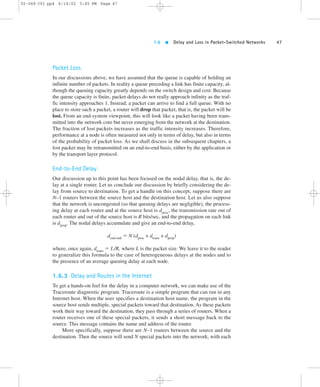
and loss in a computer network, and provide simple quantitative models for end-to-end
delay, models that take into account transmission, propagation, and queuing de-lays.
We’ll then introduce some of the key architectural principles in computer
networking, namely, protocol layering and service models. Finally, we’ll close this
chapter with a brief history of computer networking.
1.1 What Is the Internet?
In this book we use the public Internet, a specific computer network, as our princi-pal
vehicle for discussing computer network protocols. But what is the Internet? We
would like to be able to give you a one-sentence definition of the Internet, a defini-tion
that you can take home and share with your family and friends. Alas, the Inter-net
is very complex, both in terms of its hardware and software components, as well
as in the services it provides.
1.1.1 A Nuts-and-Bolts Description
Instead of giving a one-sentence definition, let’s try a more descriptive approach.
There are a couple of ways to do this. One way is to describe the nuts and bolts of
the Internet, that is, the basic hardware and software components that make up the
Internet. Another way is to describe the Internet in terms of a networking infrastruc-ture
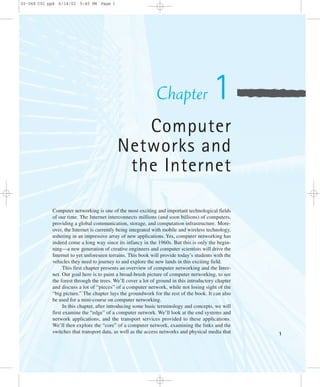
that provides services to distributed applications. Let’s begin with the nuts-and-bolts
description, using Figure 1.1 to illustrate our discussion.
The public Internet is a worldwide computer network, that is, a network that in-terconnects
millions of computing devices throughout the world. Most of these com-puting
devices are traditional desktop PCs, UNIX-based workstations, and so-called
servers that store and transmit information such as Web pages and e-mail messages.
Increasingly, nontraditional Internet end systems such as PDAs (Personal Digital
Assistants), TVs, mobile computers, automobiles, and toasters are being connected
to the Internet. (Toasters [Toasty 2002] are not the only rather unusual devices to
have been hooked up to the Internet; see “Internet Home Appliances” [Appliance
2002].) In the Internet jargon, all of these devices are called hosts or end systems.
As of January 2002 there were 100–500 million end systems using the Internet; and
this number continues to grow exponentially [ISC 2002].
End systems are connected together by communication links.We’ll see in Sec-tion
1.4 that there are many types of communication links, which are made up of dif-ferent
types of physical media, including coaxial cable, copper wire, fiber optics,](https://image.slidesharecdn.com/ch01-140904125113-phpapp01/85/Ch01-pdf-kurose-and-ross-2-320.jpg)
![02-068 C01 pp4 6/14/02 5:45 PM Page 4
4 CHAPTER 1 Computer Networks and the Internet
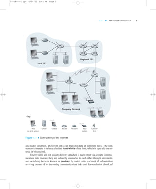
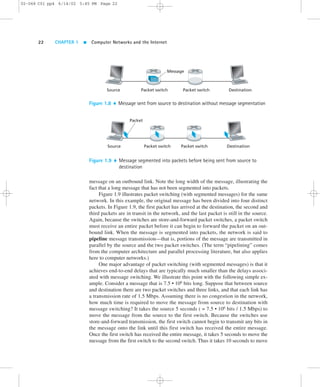
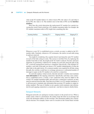
information on one of its outgoing communication links. In the jargon of computer
networking, the chunk of information is called a packet. The path that the packet
takes from the sending end system, through a series of communication links and
routers, to the receiving end system is known as a route or path through the net-work.
Rather than provide a dedicated path between communicating end systems,
the Internet uses a technique known as packet switching that allows multiple com-municating
end systems to share a path, or parts of a path, at the same time. The first
packet-switched networks, created in the 1970s, are the earliest ancestors of today’s
Internet.
End systems access the Internet through Internet Service Providers (ISPs), in-cluding
residential ISPs such as AOL or MSN, university ISPs such as Stanford Uni-versity,
and corporate ISPs such as Ford Motor Company. Each ISP is a network of
routers and communication links. The different ISPs provide a variety of different
types of network access to the end systems, including 56 Kbps dial-up modem ac-cess,
residential broadband access such as cable modem or DSL, high-speed LAN
access, and wireless access. ISPs also provide Internet access to content providers,
connecting Web sites directly to the Internet. To allow communication among Inter-net
users and to allow users to access worldwide Internet content, these lower-tier
ISPs are interconnected through national and international upper-tier ISPs, such as
the UUNet and Sprint. An upper-tier ISP consists of high-speed routers intercon-nected
with high-speed fiber-optic links. Each ISP network, whether upper-tier or
lower-tier, is managed independently, runs the IP protocol (see below), and con-forms
to certain naming and address conventions. We will examine ISPs and their
interconnection more closely in Section 1.5.
End systems, routers, and other “pieces” of the Internet, run protocols that con-trol
the sending and receiving of information within the Internet. TCP (the Trans-mission
Control Protocol) and IP (the Internet Protocol) are two of the most
important protocols in the Internet. The IP protocol specifies the format of the pack-ets
that are sent and received among routers and end systems. The Internet’s princi-pal
protocols are collectively known as TCP/IP. We begin looking into protocols in
this introductory chapter. But that’s just a start—much of this book is concerned
with computer network protocols!
The public Internet (that is, the global network of networks discussed above) is
the network that one typically refers to as the Internet. There are also many private
networks, such as many corporate and government networks, whose hosts cannot
exchange messages with hosts outside of the private network (unless the messages
pass through so-called firewalls, which restrict the flow of messages to and from the
network). These private networks are often referred to as intranets, as they use the
same types of hosts, routers, links, and protocols as the public Internet.
At the technical and developmental level, the Internet is made possible through
creation, testing, and implementation of Internet standards. These standards are
developed by the Internet Engineering Task Force (IETF)[IETF 2002]. The IETF
standards documents are called RFCs (request for comments). RFCs started out as
general requests for comments (hence the name) to resolve architecture problems](https://image.slidesharecdn.com/ch01-140904125113-phpapp01/85/Ch01-pdf-kurose-and-ross-4-320.jpg)
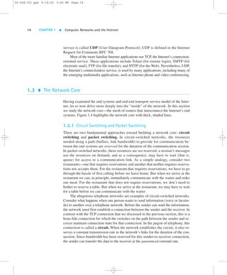
![02-068 C01 pp4 6/14/02 5:45 PM Page 10
10 CHAPTER 1 Computer Networks and the Internet
Local ISP
Regional ISP
Company Network
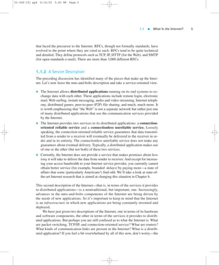
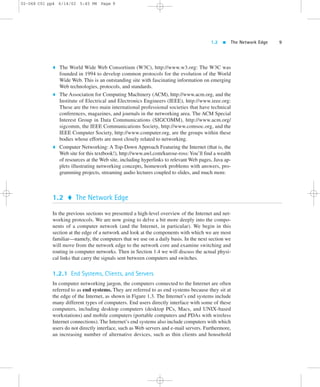
Figure 1.3 End-system interaction
appliances [Thinplanet 2002],Web TVs and set top boxes [Nesbitt 2002], and digi-tal
cameras are being attached to the Internet as end systems. For interesting discus-sions
of the future of Internet appliances see [Manelli 2001; Appliance 2001;
Dertouzos 2001; Odlyzko 1999].
End systems are also referred to as hosts because they host (that is, run) appli-cation
programs such as a Web browser program, a Web server program, an e-mail
reader program, or an e-mail server program. Throughout this book we will use the
terms hosts and end systems interchangeably; that is, host = end system. Hosts are
sometimes further divided into two categories: clients and servers. Informally,
clients tend to be desktop and mobile PCs, PDAs, and so on, whereas servers tend to
be more powerful machines hosting servers such as Web servers and mail servers.](https://image.slidesharecdn.com/ch01-140904125113-phpapp01/85/Ch01-pdf-kurose-and-ross-10-320.jpg)
![1.2 The Network Edge 11
In the context of networking software, there is another definition of a client
and server, a definition that we’ll refer to throughout this book. A client program
is a program running on one end system that requests and receives a service from a
server program running on another end system. Studied in detail in Chapter 2, this
client/server model is undoubtedly the most prevalent structure for Internet appli-cations.
The Web, e-mail, file transfer, remote login (for example, Telnet), news-groups,
and many other popular applications adopt the client/server model. Since
a client program typically runs on one computer and the server program runs on
another computer, client/server Internet applications are, by definition, distributed
applications. The client program and the server program interact with each
other by sending each
other messages over the
Internet. At this level of
abstraction, the routers,
links and other “nuts and
bolts” of the Internet serve
as a “black box” that trans-fers
messages between the
distributed, communicat-ing
components of an In-ternet
application. This is
the level of abstraction de-picted
in Figure 1.3.
Not all Internet appli-cations
today consist of
pure client programs in-teracting
with pure server
programs. For example,
with the popular peer-to-
peer file sharing appli-cations
(Napster, Gnutella,
KaZaA, and so on), the
peer-to-peer application in
the user’s end system acts
as both a client program
and a server program. The
program running in a peer
(that is, a user’s machine)
acts as a client when it re-quests
a file from another
peer; and the program acts
as a server when it sends a
file to another peer.
Case History
SEARCH FOR EXTRATERRESTRIAL LIFE
One of the niftiest applications of the Internet is the SETI@home project
[SETI@home 2002], a scientific experiment that uses Internet-connected comput-ers
in the Search for Extraterrestrial Intelligence (SETI). Anyone can participate by
running a free client program that downloads and analyzes radio telescope data.
The goal of the project is to find, in the radio telescope data, signals that were cre-ated
by extraterrestrial life.
SETI@home searches for signs of intelligent life by analyzing radio data that
are collected from Arecibo, the largest radio telescope in the world, located in the
hills of northern Puerto Rico. Massive quantities of radio data are collected on
tapes and sent to Berkeley every week. At Berkeley, the data is divided into work
units of about 300 Kbytes, which are stored in a central SETI@home server. To
participate in this project, an Internet user (for example, you!) first downloads a
client program from SETI@home that runs in the background on a host computer
(for example, your PC). The client program then sets up a TCP connection to the
central server, obtains a work unit, and closes the connection. Once a host has ob-tained
a work unit, it processes the data—mostly FFT (Fast Fourier Transform) cal-culations—
which may take from an hour to several days, depending on the power
and usage of the host. When the calculations are finished, the client program re-connects
to the central server, sends back the results, and gets a new work unit.
Today, over 3 million users from more than 200 countries have downloaded and
run the client program. In a typical day, the hosts together perform over 20 trillion
floating-point operations per second, which is faster than the largest of the super-computers.
And the SETI@home project is only the tip of the iceberg for peer-based
scientific computing. If 10 percent of the approximately one billion Internet-connected
hosts participate in peer-based computing projects, there will be enough
computing power for 100 projects the size of SETI@home [Anderson 2001].
➤
02-068 C01 pp4 6/14/02 5:45 PM Page 11](https://image.slidesharecdn.com/ch01-140904125113-phpapp01/85/Ch01-pdf-kurose-and-ross-11-320.jpg)
![1.2 The Network Edge 13
02-068 C01 pp4 6/14/02 5:45 PM Page 13
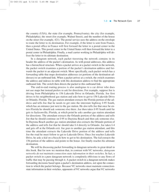
When end system B receives a packet from A, it sends an acknowledgment; when
end system A receives the acknowledgment, it knows that the corresponding packet
has definitely been received. When end system A doesn’t receive an acknowledg-ment,
it assumes the packet it sent wasn’t received by B and thus retransmits the
packet. Flow control makes sure that neither side of a connection overwhelms the
other side by sending too many packets too fast. Indeed, there is a risk that the re-ceiver
may not be able to keep up with the rate at which the sender is sending pack-ets.
The flow-control service forces the sending end system to reduce its rate
whenever there is such a risk. We’ll see in Chapter 3 that the Internet implements
the flow-control service by using sender and receiver buffers in the communicating
end systems. The Internet’s congestion-control service helps prevent the Internet
from entering a state of gridlock. When a router becomes congested, its buffers can
overflow and packet loss can occur. In such circumstances, if every pair of commu-nicating
end systems continues to pump packets into the network as fast as they can,
gridlock sets in and few packets are delivered to their destinations. The Internet
avoids this problem by forcing end systems to decrease the rate at which they send
packets into the network during periods of congestion. End systems are alerted to
the existence of severe congestion when they stop receiving acknowledgments for
the packets they have sent.
We emphasize here that although the Internet’s connection-oriented service
comes bundled with reliable data transfer, flow control, and congestion control,
these three features are by no means essential components of a connection-oriented
service. A different type of computer network may provide a connection-oriented
service to its applications without bundling in one or more of these features. Indeed,
any protocol that performs handshaking between the communicating entities before
transferring data is a connection-oriented service [Iren 1999].
The Internet’s connection-oriented service has a name—TCP (Transmission
Control Protocol); the initial version of the TCP protocol is defined in the Internet
Request for Comments RFC 793 [RFC 793]. The services that TCP provides to an
application include reliable transport, flow control, and congestion control. It is im-portant
to note that an application need only care about the services that are pro-vided;
it need not worry about how TCP actually implements reliability, flow
control, or congestion control. We, of course, are very interested in how TCP imple-ments
these services, and we shall cover these topics in detail in Chapter 3.
Connectionless Service
There is no handshaking with the Internet’s connectionless service. When one side
of an application wants to send packets to the other side of the application, the
sending program simply sends the packets. Since there is no handshaking proce-dure
prior to data packet transmission, data can be delivered sooner. But there is no
reliable data transfer either, so a source never knows for sure which packets have
arrived at the destination. Moreover, the Internet’s connectionless service makes no
provision for flow control or congestion control. The Internet’s connectionless](https://image.slidesharecdn.com/ch01-140904125113-phpapp01/85/Ch01-pdf-kurose-and-ross-13-320.jpg)
![02-068 C01 pp4 6/14/02 5:45 PM Page 30
30 CHAPTER 1 Computer Networks and the Internet
1.4.1 Network Access
Network access can be loosely classified into three categories:
Residential access, connecting home end systems into the network
Company access, connecting end systems in a business or educational institu-tion
into the network
Mobile access, connecting mobile end systems into the network
These categories are not hard and fast—for example, some company end systems
may use the access technology that we ascribe to residential access, and vice versa.
The following descriptions are meant to hold for the common cases.
Residential Access
Residential access refers to connecting a home end system (typically a PC, but per-haps
a Web TV or some Internet home appliance) to an edge router. A prevalent
form of residential access remains the dial-up modem over an ordinary analog tele-phone
line into a residential ISP (such as America Online). The home modem con-verts
the digital output of the PC into analog format for transmission over the analog
phone line. This analog phone line is made of twisted-pair copper wire, and is the
same telephone line used to make ordinary phone calls. (We will discuss twisted pair
later in this section.) At the other end of the analog phone line, a modem in the ISP
converts the analog signal back into digital form for input to the ISP router. Thus,
the access network is simply a pair of modems along with a point-to-point dial-up
phone line. Today’s modem speeds allow dial-up access at rates up to 56 Kbps.
However, due to the poor quality of the twisted-pair line between many homes and
ISPs, many users get an effective rate significantly less than 56 Kbps.
Many residential users find a dial-up modem’s 56 Kbps access to be excruciat-ingly
slow. For example, it takes approximately eight minutes to download a single
three-minute MP3 song over a 56 Kbps dial-up modem. Moreover, dial-up modem
access ties up a user’s ordinary phone line—while a residential user uses a dial-up
modem to surf the Web, the user cannot receive and make ordinary phone calls over
the phone line. Fortunately, new broadband access technologies are providing resi-dential
users higher bit rates; and they are also providing a means for users to access
the Internet and talk on the phone at the same time. There are two common types of
broadband residential access: digital subscriber line (DSL) [DSL 2002] and hy-brid
fiber coaxial cable (HFC) [Cable 2002].
As of January 2001, broadband residential access was much less prevalent than
56 Kbps dial-up modem access: the percentage of homes with broadband Internet
access was 9.2 percent in South Korea, 4.2 percent in Canada, and 2.2 percent in the
United States, with even lower penetration rates in Europe [Economist 2001]. How-ever,
DSL and HFC are being rapidly deployed throughout the world, with HFC be-](https://image.slidesharecdn.com/ch01-140904125113-phpapp01/85/Ch01-pdf-kurose-and-ross-30-320.jpg)
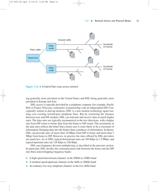
![1.4 Network Access and Physical Media 33
02-068 C01 pp4 6/14/02 5:45 PM Page 33
Company Access
On corporate and university campuses, a local area network (LAN) is typically used to
connect an end system to the edge router. As we will see in Chapter 5, there are many
different types of LAN technology. However, Ethernet technology is currently by far
the most prevalent access technology in company networks. Ethernet operates at 10
Mbps or 100 Mbps (and now even at 1 Gbps and 10 Gbps). It uses either twisted-pair
copper wire or coaxial cable to connect a number of end systems with each other and
with an edge router. The edge router is responsible for routing packets that have desti-nations
outside of that LAN. Like HFC, Ethernet uses a shared medium, so that end
users share the transmission rate of the LAN. More recently, shared Ethernet technol-ogy
has been migrating toward switched Ethernet technology. Switched Ethernet uses
multiple twisted-pair Ethernet segments connected at a “switch” to allow the full
bandwidth of an Ethernet to be delivered to different users on the same LAN simulta-neously.
We will explore shared and switched Ethernet in detail in Chapter 5.
Mobile Access
Accompanying the current Internet revolution, the wireless revolution is also having
a profound impact on the way people work and live. In the year 2000, more people
in Europe had a mobile phone than had a PC or a car. And the wireless trend is con-tinuing,
with many analysts predicting that mobile handheld devices—such as mo-bile
phones and PDAs—will overtake wired computers as the dominant Internet
access devices throughout the world by 2004 [Dornan 2001]. Today, there are
two broad types of wireless Internet access. In a wireless LAN, mobile users trans-mit/
receive packets to/from a base station (also known as a wireless access point)
within a radius of a few tens of meters. The base station is typically connected to the
wired Internet and thus serves to connect wireless users to the wired network. In
wide-area wireless access networks, the base station is managed by a telecommu-nications
provider and serves users within a radius of tens of kilometers.
Wireless LANs, based on IEEE 802.11b technology (also known as wireless
Ethernet and Wi-Fi), are currently enjoying rapid deployment in university depart-ments,
business offices, coffee cafes, and homes. For example, Polytechnic Univer-sity
has installed IEEE 802.11b base stations on its Brooklyn campus, and all of
Polytechnic’s students are required to purchase a portable computer equipped with
802.11b. Using this wireless LAN infrastructure, students send and receive e-mail
or surf the Web from anywhere on campus (for example, library, dorm room, class-room,
or outdoor campus bench). The 802.11b technology, which we will discuss in
detail in Chapter 5, provides a shared bandwidth of 11 Mbps.
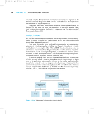
Today many homes are combining broadband residential access (that is, cable
modems or DSL) with inexpensive wireless LAN technology to create powerful
home networks. Figure 1.16 shows a schematic of a typical home network (actually,](https://image.slidesharecdn.com/ch01-140904125113-phpapp01/85/Ch01-pdf-kurose-and-ross-33-320.jpg)
![02-068 C01 pp4 6/14/02 5:45 PM Page 34
34 CHAPTER 1 Computer Networks and the Internet
Cable
headend
House
Internet
Figure 1.16 A schematic of a typical home network
this is precisely the home network setup of one of the authors). This home network
consists of a roaming laptop as well as a stationary PC; a base station (the wireless
access point) which communicates with the roaming PC; a cable modem, providing
the broadband access to the Internet; and a router, which interconnects the base sta-tion
and the stationary PC with the cable modem. This network allows two house-hold
members to have broadband access to the Internet, with one member roaming
from the kitchen to the backyard to the bedrooms. The total fixed cost for such a net-work
is less than $500 (including the cable/DSL modem) and is dropping rapidly
[Bricklin 2001].
When you access the Internet through wireless LAN technology, you typically
need to be within a few tens of meters of a base station. This is feasible for home ac-cess,
coffee shop access, and, more generally, access within and around a building.
But what if you are on the beach or in your car and you need Internet access? For
such wide-area access, roaming Internet users make use of the portable phone infra-structure,
accessing base stations that are up to tens of kilometers away.
WAP (wireless access protocol), widely available in Europe, and i-mode, widely
available in Japan, are two technologies that allow for Internet access over the portable
phone infrastructure. Resembling ordinary wireless phones but with somewhat bigger
screens, WAP phones provide low-speed Internet access as well as portable phone
service. Instead of HTML, WAP phones use a special markup language—WML
(WAP Markup Language)—that has been optimized for small screens and low-speed
access. In Europe, the WAP protocol runs on top of Europe’s highly successful GSM
wireless telephony infrastructure, which uses time-division multiplexing. WAP has](https://image.slidesharecdn.com/ch01-140904125113-phpapp01/85/Ch01-pdf-kurose-and-ross-34-320.jpg)
![1.4 Network Access and Physical Media 35
02-068 C01 pp4 6/14/02 5:45 PM Page 35
been a flop in Europe to date but is expected to become more popular when the new
GPRS (General Packet Radio Service) packet technology is widely available in
2002–2003. On the other hand, the proprietary i-mode technology, which is similar in
concept and functionality to WAP, has been a huge success in Japan.
Telecommunications companies are currently making enormous investments in
3G, standing for Third Generation wireless, which will provide packet-switched
wide-area wireless Internet access at speeds in excess of 384 Kbps [Dornan 2001].
3G systems should provide high-speed access to the Web and interactive video, and
should provide voice quality that is better than that of an ordinary wired telephone.
The first 3G systems have been deployed in Japan. With such huge investments be-ing
made in 3G technology, infrastructure, and licenses, many analysts (and in-vestors!)
wonder whether 3G will be the great success that it is hyped to be. Will it
instead lose out to competing technologies such as IEEE 802.11? The jury is still
out. (See [Weinstein 2002] and the case history in Section 5.7.)
1.4.2 Physical Media
In the previous subsection, we gave an overview of some of the most important net-work
access technologies in the Internet. As we described these technologies, we
also indicated the physical media used. For example, we said that HFC uses a com-bination
of fiber cable and coaxial cable. We said that dial-up 56 Kbps modems and
ADSL use twisted-pair copper wire. And we said that mobile access networks use
the radio spectrum. In this subsection we provide a brief overview of these and other
transmission media that are commonly employed in the Internet.
In order to define what is meant by a physical medium, let us reflect on the brief
life of a bit. Consider a bit traveling from one end system, through a series of links
and routers, to another end system. This poor bit gets transmitted many, many times!
The source end system first transmits the bit, and shortly thereafter the first router in
the series receives the bit; the first router then transmits the bit, and shortly there-after
the second router receives the bit; and so on. Thus our bit, when traveling from
source to destination, passes through a series of transmitter-receiver pairs. For each
transmitter-receiver pair, the bit is sent by propagating electromagnetic waves or op-tical
pulses across a physical medium. The physical medium can take many shapes
and forms and does not have to be of the same type for each transmitter-receiver pair
along the path. Examples of physical media include twisted-pair copper wire, coax-ial
cable, multi-mode fiber-optic cable, terrestrial radio spectrum, and satellite radio
spectrum. Physical media fall into two categories: guided media and unguided
media. With guided media, the waves are guided along a solid medium, such as a
fiber-optic cable, a twisted-pair copper wire, or a coaxial cable. With unguided me-dia,
the waves propagate in the atmosphere and in outer space, such as in a wireless
LAN or a digital satellite channel.
But before we get into the characteristics of the various media types, let us say
a few words about their costs. The actual cost of the physical link (copper wire,](https://image.slidesharecdn.com/ch01-140904125113-phpapp01/85/Ch01-pdf-kurose-and-ross-35-320.jpg)
![02-068 C01 pp4 6/14/02 5:45 PM Page 38
38 CHAPTER 1 Computer Networks and the Internet
home in a residential access network. [Goralski 2001], [Ramaswami 1998], and
[Green 1992] provide in-depth coverage of optical networks.
Terrestrial Radio Channels
Radio channels carry signals in the electromagnetic spectrum. They are an attractive
medium because they require no physical wire to be installed, can penetrate walls,
provide connectivity to a mobile user, and can potentially carry a signal for long
distances. The characteristics of a radio channel depend significantly on the propa-gation
environment and the distance over which a signal is to be carried. Environ-mental
considerations determine path loss and shadow fading (which decrease the
signal strength as the signal travels over a distance and around/through obstructing
objects), multipath fading (due to signal reflection off of interfering objects), and in-terference
(due to other radio channels or electromagnetic signals).
Terrestrial radio channels can be broadly classified into two groups: those
that operate in local areas, typically spanning from ten to a few hundred meters;
and those that operate in the wide area, spanning tens of kilometers. The wireless
LAN products described in Section 1.4.1 use local-area radio channels; WAP,
i-mode, and 3G technologies, also discussed in Section 1.4.1, use wide-area radio
channels. See [Dornan 2001] for a survey and discussion of the technology and
products.
Satellite Radio Channels
A communication satellite links two or more Earth-based microwave transmitter/re-ceivers,
known as ground stations. The satellite receives transmissions on one fre-quency
band, regenerates the signal using a repeater (discussed below), and
transmits the signal on another frequency. Satellites can provide bandwidths in the
gigabit per second range. Two types of satellites are used in communications: geo-stationary
satellites and low-altitude satellites.
Geostationary satellites permanently remain above the same spot on Earth. This
stationary presence is achieved by placing the satellite in orbit at 36,000 kilometers
above Earth’s surface. This huge distance from ground station through satellite back
to ground station introduces a substantial signal propagation delay of 250 millisec-onds.
Nevertheless, satellite links, which can operate at speeds of hundreds of Mbps,
are often used in telephone networks and in the backbone of the Internet.
Low-altitude satellites are placed much closer to Earth and do not remain per-manently
above one spot on Earth. They rotate around Earth just as the Moon does.
To provide continuous coverage to an area, many satellites need to be placed in or-bit.
There are currently many low-altitude communication systems in development.
Lloyd’s satellite constellation Web page [Wood 2002] provides and collects infor-mation
on satellite constellation systems for communications. Low-altitude satellite
technology may be used for Internet access sometime in the future.](https://image.slidesharecdn.com/ch01-140904125113-phpapp01/85/Ch01-pdf-kurose-and-ross-38-320.jpg)
![1.6 Delay and Loss in Packet-Switched Networks 41
02-068 C01 pp4 6/14/02 5:45 PM Page 41
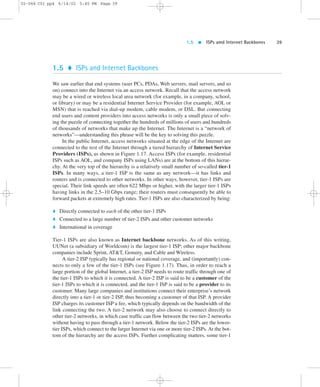
erated by either some third-party telecommunications company or by an Internet
backbone provider. NAPs exchange huge quantities of traffic among many ISPs.
However, increasingly, tier-1 ISPs are bypassing the NAPs and are interconnecting
directly at private peering points [Kende 2000]. The trend is for the tier-1 ISPs to in-terconnect
with each other directly at private peering points, and for tier-2 ISPs to
interconnect with other tier-2 ISPs and with tier-1 ISPs at NAPs. Because the NAPs
relay and switch tremendous volumes of traffic, they are in themselves complex
high-speed switching networks, often concentrated in a single building. Often a
NAP uses high-speed ATM switching technology in the heart of the NAP, with IP
riding on top of ATM. (ATM is discussed in Chapter 5.)
In summary, the topology of the Internet is complex, consisting of dozens of
tier-1 and tier-2 ISPs and thousands of lower-tier ISPs. The ISPs are diverse in their
coverage, with some spanning multiple continents and oceans, and others limited to
narrow regions of the world. The lower-tier ISPs connect to the higher-tier ISPs, and
the higher-tier ISPs interconnect at (typically) private peering points and NAPs.
Users and content providers are customers of lower-tier ISPs, and lower-tier ISPs
are customers of higher-tier ISPs.
We conclude this section by mentioning that any one of us can become an ac-cess
ISP as soon as we have an Internet connection. All we need to do is purchase
the necessary equipment (for example, router and modem pool) to allow other users
to connect to us. Thus new tiers and branches can be added to the Internet topology
just as a new piece of Lego can be attached to an existing Lego construction.
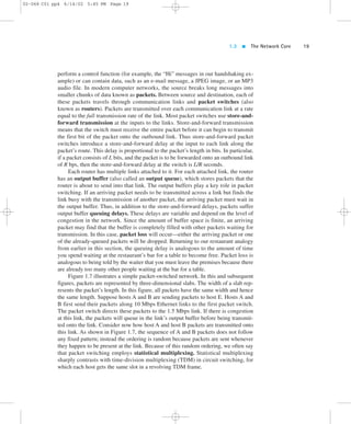
1.6 Delay and Loss in Packet-Switched Networks
Having now briefly considered the major pieces of the Internet architecture—the ap-plications,
end systems, end-to-end transport protocols, routers, and links—let us now
consider what can happen to a packet as it travels from its source to its destination. Re-call
that a packet starts in a host (the source), passes through a series of routers, and
ends its journey in another host (the destination). As a packet travels from one node
(host or router) to the subsequent node (host or router) along this path, the packet suf-fers
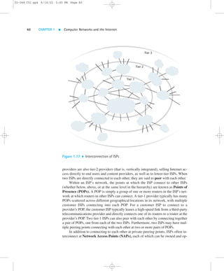
from several different types of delays at each node along the path. The most im-portant
of these delays are the nodal processing delay, queuing delay, transmission
delay, and propagation delay; together, these delays accumulate to give a total nodal
delay. In order to acquire a deep understanding of packet switching and computer net-works,
we must understand the nature and importance of these delays.
1.6.1 Types of Delay
Let us explore these delays in the context of Figure 1.18. As part of its end-to-end
route between source and destination, a packet is sent from the upstream node](https://image.slidesharecdn.com/ch01-140904125113-phpapp01/85/Ch01-pdf-kurose-and-ross-41-320.jpg)
![1.6 Delay and Loss in Packet-Switched Networks 45
02-068 C01 pp4 6/14/02 5:45 PM Page 45
dominant term in dnodal. Similarly, dtrans can range from negligible to significant. Its
contribution is typically negligible for transmission rates of 10 Mbps and higher (for
example, for LANs); however, it can be hundreds of milliseconds for large Internet
packets sent over low-speed dial-up modem links. The processing delay, dproc, is
often negligible; however, it strongly influences a router’s maximum throughput,
which is the maximum rate at which a router can forward packets.
1.6.2 Queuing Delay and Packet Loss
The most complicated and interesting component of nodal delay is the queuing de-lay,
dqueue. In fact, queuing delay is so important and interesting in computer net-working
that thousands of papers and numerous books have been written about it
[Bertsekas 1991; Daigle 1991; Kleinrock 1975, 1976; Ross 1995]! We give only a
high-level, intuitive discussion of queuing delay here; the more curious reader may
want to browse through some of the books (or even eventually write a Ph.D. thesis
on the subject!). Unlike the other three delays (namely, dproc, dtrans, and dprop), the
queuing delay can vary from packet to packet. For example, if ten packets arrive at
an empty queue at the same time, the first packet transmitted will suffer no queuing
delay, while the last packet transmitted will suffer a relatively large queuing delay
(while it waits for the other nine packets to be transmitted). Therefore, when charac-terizing
queuing delay, one typically uses statistical measures, such as average queu-ing
delay, variance of queuing delay, and the probability that the queuing delay
exceeds some specified value.
When is the queuing delay large and when is it insignificant? The answer to this
question depends largely on the rate at which traffic arrives at the queue, the trans-mission
rate of the link, and the nature of the arriving traffic, that is, whether the
traffic arrives periodically or whether it arrives in bursts. To gain some insight here,
let a denote the average rate at which packets arrive at the queue (a is in units of
packets/sec). Recall that R is the transmission rate; that is, it is the rate (in bits/sec)
at which bits are pushed out of the queue. Also suppose, for simplicity, that all pack-ets
consist of L bits. Then the average rate at which bits arrive at the queue is La
bits/sec. Finally, assume that the queue is very big, so that it can hold essentially an
infinite number of bits. The ratio La/R, called the traffic intensity, often plays an
important role in estimating the extent of the queuing delay. If La/R . 1, then the
average rate at which bits arrive at the queue exceeds the rate at which the bits can
be transmitted from the queue. In this unfortunate situation, the queue will tend to
increase without bound and the queuing delay will approach infinity! Therefore, one
of the golden rules in traffic engineering is: Design your system so that the traffic
intensity is no greater than 1.
Now consider the case La/R # 1. Here, the nature of the arriving traffic impacts
the queuing delay. For example, if packets arrive periodically—that is, one packet ar-rives
every L/R seconds—then every packet will arrive at an empty queue and there
will be no queuing delay. On the other hand, if packets arrive in bursts but periodically,](https://image.slidesharecdn.com/ch01-140904125113-phpapp01/85/Ch01-pdf-kurose-and-ross-45-320.jpg)
![02-068 C01 pp4 6/14/02 5:45 PM Page 54
54 CHAPTER 1 Computer Networks and the Internet
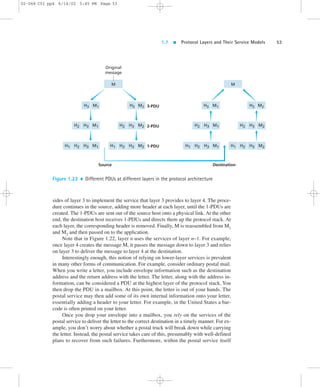
there are layers, and the protocols at one layer rely on and use the services of the
layer below.
In order for one layer to interoperate with the layer below it, the interfaces be-tween
the two layers must be precisely defined. Standards bodies define precisely
the interfaces between adjacent layers (for example, the format of the PDUs passed
between the layers) and permit the developers of networking software and hardware
to implement the interior of the layers as they please. Therefore, if a new and im-proved
implementation of a layer is released, the new implementation can replace
the old implementation and, in theory, the layers will continue to interoperate.
Layer Functions
In a computer network, each layer may perform one or more of the following
generic set of tasks:
Error control, which makes the logical channel between the layers in two peer
network elements more reliable
Flow control, which avoids overwhelming a slower peer with PDUs
Segmentation and reassembly, which at the transmitting side divides, large data
chunk into smaller pieces and at the receiving side reassembles the smaller
pieces into the original large chunk
Multiplexing, which allows several higher-level sessions to share a single lower-level
connection
Connection setup, which provides handshaking with a peer
Protocol layering has conceptual and structural advantages. We mention, however,
that some researchers and networking engineers are vehemently opposed to layering
[Wakeman 1992]. One potential drawback of layering is that one layer may duplicate
lower-layer functionality. For example, many protocol stacks provide error recovery
on both a link basis and an end-to-end basis. A second potential drawback is that
functionality at one layer may need information (for example, a timestamp value)
that is present only in another layer; this violates the goal of separation of layers.
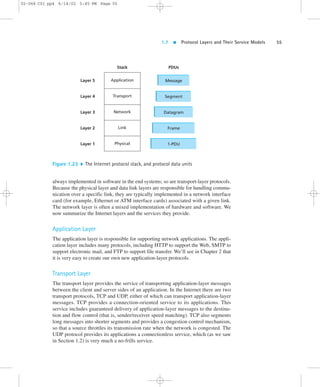
1.7.2 The Internet Protocol Stack
The Internet stack consists of five layers: the physical, data link, network, transport,
and application layers. Rather than use the cumbersome terminology n-PDU for
each of the five layers, we instead give special names to the PDUs in four of the five
layers: frame, datagram, segment, and message. We don’t name a data unit for the
physical layer, as no name is commonly used at this layer. The Internet stack and the
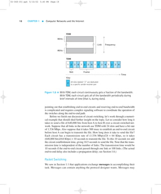
corresponding PDU names are illustrated in Figure 1.23.
A protocol layer can be implemented in software, in hardware, or in a combina-tion
of the two. Application-layer protocols—such as HTTP and SMTP—are almost](https://image.slidesharecdn.com/ch01-140904125113-phpapp01/85/Ch01-pdf-kurose-and-ross-54-320.jpg)
![02-068 C01 pp4 6/14/02 5:45 PM Page 58
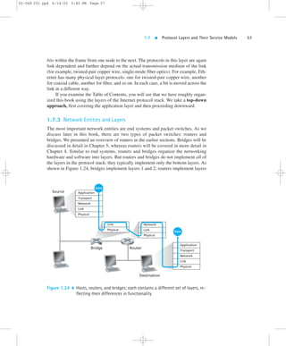
58 CHAPTER 1 Computer Networks and the Internet
1 through 3. This means, for example, that Internet routers are capable of imple-menting
the IP protocol (a layer 3 protocol), while bridges are not. We will see later
that while bridges do not recognize IP addresses, they are capable of recognizing
layer 2 addresses, such as Ethernet addresses. Note that hosts implement all five lay-ers;
this is consistent with the view that the Internet architecture puts much of its
complexity at the “edges” of the network.
1.8 History of Computer Networking and the Internet
Sections 1.1–1.7 presented an overview of the technology of computer networking and
the Internet. You should know enough now to impress your family and friends! How-ever,
if you really want to be a big hit at the next cocktail party, you should sprinkle
your discourse with tidbits about the fascinating history of the Internet [Segaller 1998].
1.8.1 The Development of Packet Switching: 1961–1972
The field of computer networking and today’s Internet trace their beginnings back
to the early 1960s, a time at which the telephone network was the world’s dominant
communication network. Recall from Section 1.3 that the telephone network uses
circuit switching to transmit information from a sender to receiver—an appropriate
choice given that voice is transmitted at a constant rate between sender and receiver.
Given the increasing importance (and great expense) of computers in the early
1960s and the advent of timeshared computers, it was perhaps natural (at least with
perfect hindsight!) to consider the question of how to hook computers together so
that they could be shared among geographically distributed users. The traffic gener-ated
by such users was likely to be “bursty”—intervals of activity, such as the send-ing
of a command to a remote computer, followed by periods of inactivity while
waiting for a reply or while contemplating the received response.
Three research groups around the world, all unaware of the others’work [Leiner
1998], began inventing the notion of packet switching as an efficient and robust al-ternative
to circuit switching. The first published work on packet-switching tech-niques
was that of Leonard Kleinrock [Kleinrock 1961; Kleinrock 1964], at that
time a graduate student at MIT. Using queuing theory, Kleinrock’s work elegantly
demonstrated the effectiveness of the packet-switching approach for bursty traffic
sources. In 1964, Paul Baran [Baran 1964] at the Rand Institute had begun investi-gating
the use of packet switching for secure voice over military networks, and at
the National Physical Laboratory in England, Donald Davies and Roger Scantlebury
were also developing their ideas on packet switching.
The work at MIT, Rand, and NPL laid the foundations for today’s Internet. But
the Internet also has a long history of a let’s-build-it-and-demonstrate-it attitude that](https://image.slidesharecdn.com/ch01-140904125113-phpapp01/85/Ch01-pdf-kurose-and-ross-58-320.jpg)
![1.8 History of Computer Networking and the Internet 59
02-068 C01 pp4 6/14/02 5:45 PM Page 59
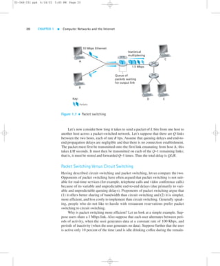
Figure 1.25 The first interface message processor (IMP), with L. Kleinrock
also dates back to the early 1960s. J.C.R. Licklider [DEC 1990] and Lawrence
Roberts, both colleagues of Kleinrock’s at MIT, went on to lead the computer sci-ence
program at the Advanced Research Projects Agency (ARPA) in the United
States. Roberts published an overall plan for the so-called ARPAnet [Roberts 1967],
the first packet-switched computer network and a direct ancestor of today’s public
Internet. The early packet switches were known as interface message processors
(IMPs), and the contract to build these switches was awarded to the BBN company.
On Labor Day in 1969, the first IMP was installed at UCLA under Kleinrock’s su-pervision,
with three additional IMPs being installed shortly thereafter at the Stan-ford
Research Institute (SRI), UC Santa Barbara, and the University of Utah (Figure
1.25). The fledgling precursor to the Internet was four nodes large by the end of
1969. Kleinrock recalls the very first use of the network to perform a remote login
from UCLA to SRI, crashing the system [Kleinrock 1998].
By 1972, ARPAnet had grown to approximately 15 nodes, and was given its
first public demonstration by Robert Kahn at the 1972 International Conference on
Computer Communications. The first host-to-host protocol between ARPAnet end
systems, known as the network-control protocol (NCP), was completed [RFC 001].](https://image.slidesharecdn.com/ch01-140904125113-phpapp01/85/Ch01-pdf-kurose-and-ross-59-320.jpg)
![02-068 C01 pp4 6/14/02 5:45 PM Page 60
60 CHAPTER 1 Computer Networks and the Internet
With an end-to-end protocol available, applications could now be written. The first
e-mail program was written by Ray Tomlinson at BBN in 1972.
1.8.2 Proprietary Networks and Internetworking: 1972–1980
The initial ARPAnet was a single, closed network. In order to communicate with an
ARPAnet host, one had to be actually attached to another ARPAnet IMP. In the early to
mid-1970s, additional packet-switching networks besides ARPAnet came into being:
ALOHAnet, a microwave network linking together universities on the Hawaiian
islands [Abramson 1970]
Telenet, a BBN commercial packet-switching network based on ARPAnet tech-nology
Cyclades, a French packet-switching network pioneered by Louis Pouzin [Think
2002]
Time-sharing networks such as Tymnet and the GE Information Services net-work,
among others in the late 1960s to early 1970s [Schwartz 1977]
IBM’s SNA (1969–1974), which paralleled the ARPAnet work [Schwartz 1977]
The number of networks was beginning to grow. In 1973, Robert Metcalfe’s Ph.D.
thesis laid out the principle of Ethernet, which would later lead to a huge growth in
so-called local area networks (LANs) that operated over a small distance based on
the Ethernet protocol.
Once again, with perfect hindsight one might now see that the time was ripe for
developing an encompassing architecture for connecting networks together. Pioneer-ing
work on interconnecting networks (once again under the sponsorship of
DARPA—Defense Advanced Research Projects Agency), in essence creating a net-work
of networks, was done by Vinton Cerf and Robert Kahn [Cerf 1974]; the term
“internetting” was coined to describe this work.
These architectural principles were embodied in the TCP protocol. The early
versions of TCP, however, were quite different from today’s TCPs. The early ver-sions
of TCP combined a reliable in-sequence delivery of data via end-system re-transmission
(still part of today’s TCP) with forwarding functions (which today
are performed by IP). Early experimentation with TCP, combined with the recog-nition
of the importance of an unreliable, non-flow-controlled end-end transport
service for applications such as packetized voice, led to the separation of IP out of
TCP and the development of the UDP protocol. The three key Internet protocols
that we see today—TCP, UDP, and IP—were conceptually in place by the end of
the 1970s.
In addition to the DARPA Internet-related research, many other important net-working
activities were under way. In Hawaii, Norman Abramson was developing](https://image.slidesharecdn.com/ch01-140904125113-phpapp01/85/Ch01-pdf-kurose-and-ross-60-320.jpg)
![1.8 History of Computer Networking and the Internet 61
02-068 C01 pp4 6/14/02 5:45 PM Page 61
Figure 1.26 Metcalfe’s original conception of the Ethernet
ALOHAnet, a packet-based radio network that allowed multiple remote sites on the
Hawaiian islands to communicate with each other. The ALOHA protocol [Abram-son
1970] was the first so-called multiple-access protocol, allowing geographically
distributed users to share a single broadcast communication medium (a radio fre-quency).
Abramson’s work on multiple-access protocols was built upon by Metcalfe
and Boggs in the development of the Ethernet protocol [Metcalfe 1976] for wire-based
shared broadcast networks; see Figure 1.26. Interestingly, Metcalfe and
Boggs’ Ethernet protocol was motivated by the need to connect multiple PCs, print-ers,
and shared disks together [Perkins 1994]. Twenty-five years ago, well before the
PC revolution and the explosion of networks, Metcalfe and Boggs were laying the
foundation for today’s PC LANs. Ethernet technology represented an important step
for internetworking as well. Each Ethernet local area network was itself a network,
and as the number of LANs proliferated, the need to internetwork these LANs to-gether
became increasingly important. We discuss Ethernet, ALOHA, and other
LAN technologies in detail in Chapter 5.
1.8.3 A Proliferation of Networks: 1980–1990
By the end of the 1970s, approximately 200 hosts were connected to the ARPAnet.
By the end of the 1980s the number of hosts connected to the public Internet, a con-federation
of networks looking much like today’s Internet, would reach 100,000.
The 1980s would be a time of tremendous growth.](https://image.slidesharecdn.com/ch01-140904125113-phpapp01/85/Ch01-pdf-kurose-and-ross-61-320.jpg)
![02-068 C01 pp4 6/14/02 5:45 PM Page 62
62 CHAPTER 1 Computer Networks and the Internet
Much of the growth in the early 1980s resulted from several distinct efforts to
create computer networks linking universities together. BITNET provided e-mail
and file transfers among several universities in the Northeast. CSNET (computer
science network) was formed to link together university researchers without access
to ARPAnet. In 1986, NSFNET was created to provide access to NSF-sponsored
supercomputing centers. Starting with an initial backbone speed of 56 Kbps,
NSFNET’s backbone would be running at 1.5 Mbps by the end of the decade, and
would be serving as a primary backbone linking together regional networks.
In the ARPAnet community, many of the final pieces of today’s Internet archi-tecture
were falling into place. January 1, 1983, saw the official deployment of
TCP/IP as the new standard host protocol for ARPAnet (replacing the NCP proto-col).
The transition [RFC 801] from NCP to TCP/IP was a “flag day” type event—
all hosts were required to transfer over to TCP/IP as of that day. In the late 1980s,
important extensions were made to TCP to implement host-based congestion con-trol
[Jacobson 1988]. The Domain Name System, used to map between a human-readable
Internet name (for example, gaia.cs.umass.edu) and its 32-bit IP address,
was also developed [RFC 1034].
Paralleling this development of the ARPAnet (which was for the most part a
United States effort), in the early 1980s the French launched the Minitel project, an
ambitious plan to bring data networking into everyone’s home. Sponsored by the
French government, the Minitel system consisted of a public packet-switched net-work
(based on the X.25 protocol suite, which uses virtual circuits), Minitel servers,
and inexpensive terminals with built-in low-speed modems. The Minitel became a
huge success in 1984 when the French government gave away a free Minitel terminal
to each French household that wanted one. Minitel sites included free sites—such as
a telephone directory site—as well as private sites, which collected a usage-based fee
from each user. At its peak in the mid 1990s, it offered more than 20,000 different
services, ranging from home banking to specialized research databases. It was used
by over 20 percent of France’s population, generated more than $1 billion in revenue
each year, and created 10,000 jobs. The Minitel was in a large proportion of French
homes ten years before most Americans had ever heard of the Internet.
1.8.4 The Internet Explosion: The 1990s
The 1990s were ushered in with a number of events that symbolized the continued
evolution and the soon-to-arrive commercialization of the Internet. ARPAnet, the
progenitor of the Internet, ceased to exist. MILNET and the Defense Data Network
had grown in the 1980s to carry most of the U.S. Department of Defense–related
traffic and NSFNET had begun to serve as a backbone network connecting regional
networks in the United States and national networks overseas. In 1991, NSFNET
lifted its restrictions on use of NSFNET for commercial purposes. NSFNET itself
would be decommissioned in 1995, with Internet backbone traffic being carried by
commercial Internet service providers.](https://image.slidesharecdn.com/ch01-140904125113-phpapp01/85/Ch01-pdf-kurose-and-ross-62-320.jpg)
![1.8 History of Computer Networking and the Internet 63
02-068 C01 pp4 6/14/02 5:45 PM Page 63
The main event of the 1990s, however, was to be the emergence of the World
Wide Web, which brought the Internet into the homes and businesses of millions of
people worldwide. The Web also served as a platform for enabling and deploying
hundreds of new applications, including online stock trading and banking, streamed
multimedia services, and information retrieval services. For a brief history of the
early days of the Web, see [W3C 1995].
The Web was invented at CERN by Tim Berners-Lee in 1989–1991 [Berners-
Lee 1989], based on ideas originating in earlier work on hypertext from the 1940s
by Bush [Bush 1945] and since the 1960s by Ted Nelson [Ziff-Davis 1998]. Berners-
Lee and his associates developed initial versions of HTML, HTTP, a Web server,
and a browser—the four key components of the Web. The original CERN browsers
provided only a line-mode interface. Around the end of 1992 there were about 200
Web servers in operation, this collection of servers being the tip of the iceberg for
what was about to come. At about this time several researchers were developing
Web browsers with GUI interfaces, including Marc Andreesen, who led the devel-opment
of the popular GUI browser Mosaic. Andreesen and his colleagues released
an alpha version of their browser in 1993, and in 1994 he and Jim Clark formed Mo-saic
Communications, which later became Netscape Communications Corporation
[Cusumano 1998; Quittner 1998]. By 1995, university students were using Mosaic
and Netscape browsers to surf the Web on a daily basis. At about this time com-panies—
big and small—began to operate Web servers and transact commerce over
the Web. In 1996, Microsoft started to make browsers, which started the “browser
war” between Netscape and Microsoft, which Microsoft won a few years later
[Cusumano 1998].
The second half of the 1990s was a period of tremendous growth and innovation
for the Internet, with major corporations and thousands of startups creating Internet
products and services. Internet e-mail continued to evolve with feature-rich mail
readers providing address books, attachments, hot links, and multimedia transport.
By the end of the millennium the Internet was supporting hundreds of popular appli-cations,
including four killer applications:
E-mail, including attachments and Web-accessible e-mail
The Web, including Web browsing and Internet commerce
Instant messaging, with “contact lists,” pioneered by ICQ
Peer-to-peer file sharing of MP3s, pioneered by Napster
Interestingly, the first two killer applications came from the research community,
whereas the last two were created by a few young entrepreneurs.
The period 1995–2001 was also a roller-coaster ride for the Internet in the fi-nancial
markets. Before becoming profitable companies, hundreds of Internet start-ups
IPOed (that is, started to be traded in a stock market with an Initial Public
Offering). Many companies were valued in the billions of dollars without having](https://image.slidesharecdn.com/ch01-140904125113-phpapp01/85/Ch01-pdf-kurose-and-ross-63-320.jpg)
![02-068 C01 pp4 6/14/02 5:45 PM Page 64
64 CHAPTER 1 Computer Networks and the Internet
any significant revenue streams. The Internet stocks collapsed in 2000–2001, with
many startups shutting down. Nevertheless, a number of companies emerged as big
winners in the Internet space (even if their stock prices suffered in the crash), includ-ing
Microsoft, Cisco, AOL, and Yahoo.
During the 1990s, networking research and development also made signifi-cant
advances in the areas of high-speed routers and routing (see Chapter 4) and
local area networks (see Chapter 5). The technical community struggled with the
problems of defining and implementing an Internet service model for traffic re-quiring
real-time constraints, such as continuous media applications (see Chapter
6). The need to secure and manage Internet infrastructure (see Chapters 7 and 8)
also became of paramount importance as e-commerce applications proliferated
and the Internet became a central component of the world’s telecommunications
infrastructure.
1.8.5 Recent Developments
Innovation in computer networking continues at a rapid pace. Advances are being
made on all fronts, including deployment of new applications, security, content dis-tribution,
Internet telephony, higher transmission speeds in LANs, and faster routers.
But there are three developments that merit special attention: broadband residential
Internet access, wireless Internet access, and peer-to-peer (P2P) networking.
Broadband residential Internet access, using cable modem and DSL technol-ogy
(discussed in Section 1.4), is enjoying rapid deployment throughout the world.
Many analysts predict that by 2005 roughly 50 percent of residential access will be
broadband. This sets the stage for a wealth of new multimedia applications, includ-ing
streaming high-quality video-on-demand and high-quality interactive video
conferencing.
Wireless Internet access has already been deployed in Japan with tremendous
success with i-mode, NTT’s DoCoMo’s mobile Internet access system [DoCoMo
2002]. The typical i-mode handset resembles an ordinary mobile phone but with a
somewhat larger screen for displaying text and images. The handsets provide both
mobile telephone and mobile Internet access. As of August 2001, there were over 20
million i-mode subscribers in Japan, and the number continues to grow rapidly. In
Europe and North America, numerous deployments of wireless Internet technolo-gies
are currently taking place. The i-mode technology leverages the mobile phone
infrastructure to provide low-speed wide-area mobile access to the Internet. The first
few years of the new decade also witnessed the rapid deployment of wireless LANs,
providing higher-speed wireless access to the Internet from hotels, cafes, corporate
buildings, university buildings, and homes.
The last innovation of which we take special note is that of P2P networking.
A P2P networking application exploits the resources in users’ computers—stor-age,
content, CPU cycles, and human presence—and has significant autonomy](https://image.slidesharecdn.com/ch01-140904125113-phpapp01/85/Ch01-pdf-kurose-and-ross-64-320.jpg)


![Chapter 3 using_the_internet[1]](https://cdn.slidesharecdn.com/ss_thumbnails/chapter3usingtheinternet1-100917180055-phpapp02-thumbnail.jpg?width=640&height=640&fit=bounds)


