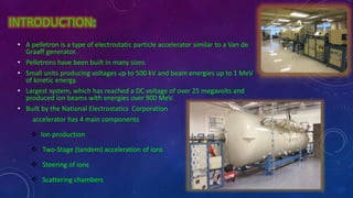
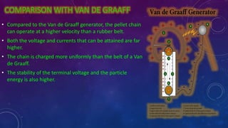
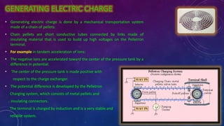
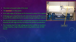
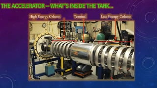
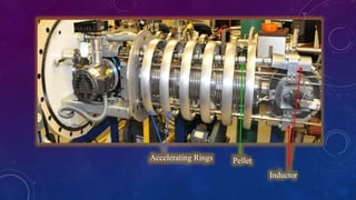
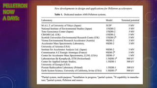
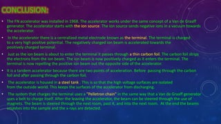
The document discusses a Pelletron tandem accelerator. A Pelletron uses a chain of metal pellets and insulating connectors to generate a high voltage on its terminal, allowing for tandem acceleration of ions. It operates similarly to a Van de Graaff generator but can achieve higher voltages and currents. Ions are produced, accelerated twice in opposite directions, steered, and directed into scattering chambers. Applications include materials analysis, medical uses, and industrial processes like radiation production and sterilization.
Accelerators are devices that use electric and magnetic fields to accelerate charged particles to high speeds. There are several types including linear accelerators (LINACs), pelletrons, and cyclotrons. The document discusses the types of accelerators at IUAC New Delhi including a 1.7 MeV and 15UD pelletron accelerators and a superconducting LINAC. It provides details on how pelletrons and LINACs work, describing the use of electric fields to speed up particles. The LINAC at IUAC uses niobium quarter wave resonators cooled with liquid helium to achieve superconductivity and accelerate beams up to 250 MeV for research.
This is a pdf file on the topic Gamow theory of alpha decay which gives description about how the scientist Gamow had solved the theory of the alpha decay via tunneling .
A betatron is a device that accelerates electrons using an expanding magnetic field within a doughnut-shaped vacuum chamber. Electrons are injected into the chamber and accelerated as the magnetic field strength increases over time. This increasing magnetic flux induces an electric field that increases the electrons' energy, allowing them to gain extremely high speeds. The betatron condition requires that the rate of change of magnetic flux through the circular orbit equals 2π times the radius squared times the rate of change of the magnetic field, in order to maintain the electrons' constant orbital radius as they accelerate.
- Cyclotrons use magnetic and electric fields to accelerate charged particles in a circular path, increasing their energy each time they pass through the accelerating field. Ernest Lawrence invented the cyclotron in the 1930s.
- Cyclotrons consist of two semicircular electrodes called dees placed between the poles of a magnet. Charged particles are accelerated as they spiral between the dees due to alternating electric fields.
- Cyclotrons are used to accelerate protons and ions for applications such as nuclear physics experiments and particle therapy for cancer treatment. They can also produce short-lived radioactive isotopes used in PET imaging. However, maintaining uniform magnetic fields over large areas is challenging for cyclotrons.
This document discusses the cyclotron, a type of particle accelerator. It begins with an introduction and overview of key topics like principles, construction, diagrams, workings, calculations, applications, and limitations. Some key points made are:
- A cyclotron accelerates charged particles like protons and deuterons using electric and magnetic fields, generating energies from 1 MeV to over 100 MeV.
- It works on the principle that a charged particle moving perpendicular to a magnetic field experiences a force causing it to travel in a circular path, with increasing radius and velocity over time due to an oscillating electric field.
- Important applications of cyclotrons include production of beams for nuclear physics experiments and cancer particle therapy.
The Compton effect
Group Name : Red Devils
Member Name & ID
Nusrat Isalm Setu -182-47-736
Md.Nazmul Hasan -182-47-722
Mohammad Imran Bhuiyan -182-47-742
Shafiul Alam -182-47-763
Kazi Hasibul Hasan -182-47-795
*FIRST INTRODUCED The Compton effect was first demonstrated in 1923 by Arthur Holly Compton (for which he received a 1927 Nobel Prize in Physics) Compton's graduate student, Y.H. Woo, later verified the effect.
DEFINITION: • The Compton effect (also called Compton scattering) is the result of a high-energy photon colliding with a target, which releases loosely bound electrons from the outer shell of the atom or molecule .
• The scattered radiation experiences a wavelength shift that cannot be explained in terms of classical wave theory, thus lending support to Einstein's photon theory.
• Probably the most important implication of the effect is that it showed light could not be fully explained according to wave phenomena.
APPLICATIONS:• Compton scattering is of prime importance to radiobiology, as it happens to be the most probable interaction of high energy X rays with atomic nuclei in living beings and is applied in radiation therapy.
• In material physics, Compton scattering can be used to probe the wave function of the electrons in matter in the momentum representation.
• Compton scattering is an important effect in gamma spectroscopy which gives rise to the Compton edge, as it is possible for the gamma rays to scatter out of the detectors used. Compton suppression is used to detect stray scatter gamma rays to counteract this effect.
equation of Compton effect:
THE EXPERIMENT: A graphite target was bombarded with monochromatic x-rays and the wavelength of the scattered radiation was measured with a rotating crystal spectrometer. The intensity was determined by a movable ionization chamber that generated a current proportional to the x-ray intensity. Compton measured the dependence of scattered x-ray intensity on wavelength at three different scattering angles of 45o 90o ,and 135o
The Experimental intensity vs wavelength plots observed by Compton for the three scattering angles show two peaks , one at the wavelength λ of the incident X-rays and the other at a longer wavelength λ’
HOW COMPTON EFFECT WORKS
This document provides information about nuclear radiation detectors. It discusses three main types of gaseous ionization detectors: ionization chambers, proportional counters, and Geiger-Müller tubes. Ionization chambers detect radiation by collecting all ion pairs created through gas ionization when radiation passes through. Proportional counters can measure radiation energy by producing output proportional to radiation energy through gas amplification of ion pairs. Geiger-Müller tubes operate at very high voltages where any initial ionization causes a self-sustaining discharge and produces a standard pulse height independent of radiation type.
The document discusses synchrotrons, which are particle accelerators that produce very bright light for research. It describes how synchrotrons work, with electrons being emitted and accelerated through components like an electron gun, linear accelerator, booster ring, and storage ring. This produces intense electromagnetic waves called synchrotron light. Synchrotron light is much brighter than standard X-rays and allows scientists to observe molecular interactions. The document outlines some of the many applications of synchrotrons, such as in materials engineering, medical imaging and therapy, environmental research, and forensics.
Nuclear radiation detectors detect nuclear particles and radiation. They work by exciting or ionizing the atoms in the material they pass through. There are different types of radiation including charged particles like alpha and beta particles, uncharged neutrons, and electromagnetic gamma rays and x-rays. Detection methods are based on the radiation interacting with the detector's base material, often ionizing or exciting its atoms. Detectors are classified as gas filled, ionization chambers, Geiger-Muller counters, semiconductors, Wilson cloud chambers or bubble chambers. Their workings exploit the properties of ionization, fluorescence, or exposing photographic plates.
This document discusses photoluminescence, which is the emission of light from a material upon exposure to light or other electromagnetic radiation. It begins by classifying luminescence and describing photoluminescence as a specific type involving absorption of photons and emission of photons as electrons return to lower energy states. The key processes of photoluminescence are excitation, relaxation, and emission. It then distinguishes between two types of photoluminescence - fluorescence, which is a rapid emission, and phosphorescence, which involves a spin-forbidden state and longer-lasting emission. The document concludes by outlining applications of photoluminescence spectroscopy for materials characterization and explaining the differences between photoluminescence and
Analysis of space charge controlled electric field 1Chandan Kumar
The document discusses space charge and its effects on cable insulation failures. Space charge forms due to inhomogeneous resistivity, ionization within dielectrics, charge injection from electrodes, and polarization. Its presence distorts electric fields inside dielectrics, potentially leading to localized breakdown. Simulation results show how voids and trapped charge can enhance electric field stresses. The document also examines space charge limited current in cable insulation and simulates the relationship between current density and voltage for parallel plate electrodes, finding good agreement with analytical solutions. Future work is proposed to further study space charge effects in cables and insulation materials.
The document summarizes key aspects of a cyclotron, which is a device that accelerates charged particles outwards in a spiral path using crossed electric and magnetic fields. It was invented in 1929 and the first operational cyclotron was built in 1932 by Ernest Lawrence. Cyclotrons work by subjecting particles to an oscillating electric field while they travel in a circle due to a static magnetic field. Modifications allow relativistic speeds. Cyclotrons are used in nuclear physics experiments and for producing isotopes for PET imaging and particle cancer therapy. Limitations include inability to accelerate neutral particles or electrons.
A synchrotron uses a cyclic particle accelerator to accelerate charged particles to very high energies using alternating electric and magnetic fields. The first electron synchrotron was constructed in 1945 by Edwin McMillan at the University of California, designed for energies between 320-350 MeV. A synchrotron consists of an electron gun, linear accelerator, booster ring, storage ring, beamline, and end station to produce and direct beams of synchrotron light for applications in spectroscopy, crystallography, medical imaging, and cancer therapy.
A free electron laser works by accelerating a beam of electrons to relativistic speeds and passing them through an undulator, which is a series of magnets that cause the electrons to oscillate. This oscillation produces intense beams of radiation whose wavelength can be tuned by adjusting the electron energy or undulator strength. Free electron lasers produce highly tunable and coherent radiation that is useful for applications like chemistry, biology, and medicine due to their ability to "see" atoms. A prominent example is the Linac Coherent Light Source, which produces intense x-rays and is the world's most powerful laser.
The document discusses ion-beam lithography, which uses a focused beam of ions instead of electrons or photons to pattern surfaces. Ion-beam lithography offers higher resolution than other lithography techniques due to ions having higher momentum and less scattering. It can define patterns through physical sputtering, chemical reactions with precursor gases, or ion implantation. While having advantages like high resolution and minimal proximity effects, it also has lower throughput and can damage substrates more than other lithography methods. The document provides details on ion sources, lithography processes, advantages and disadvantages of the technique.
Molecular beam epitaxy (MBE) is a method for growing thin films one layer at a time under ultra-high vacuum conditions. It involves heating solid sources of material in effusion cells to create molecular beams that are deposited on a heated substrate. The absence of carrier gases and ultra-high vacuum environment result in films of the highest purity. MBE is widely used to manufacture semiconductor devices and is considered a fundamental tool for nanotechnology development due to its precise control over layer thickness down to a single atomic layer.
Linear attenuation coefficient (휇) is a measure of the ability of a medium to diffuse and absorb radiation. In the interaction of radiation with matter, the linear absorption coefficient plays an important role because during the passage of radiation through a medium, its absorption depends on the wavelength of the radiation and the thickness and nature of the medium. Experiments to determine linear absorption coefficient for Lead, Copper and Aluminum were carried out in air. The result showed that linear absorption Coefficient for Lead is 0.545cm – 1, Copper is 0.139cm-1 and Aluminum is 0.271cm-1 using gamma-rays. The results agree with standard values.
cyclotron that accelerate the charge particles prior their bombardment to the target nuclei.
it is developed by E.O.Lawrence & he was awarded by nobel prize in this work. it accelerate the particle from 1MeV to the more than 100 MeV.
it contains the electric & magnetic system to accelerate the charge particles.
electric field acts horizontally & magnetic field act vertically.
particle moves in spiral path and its energy , radius & velocity increases.
after that it moves out of window ( diflactor plate) n hit the target.
n then the nuclear reaction starts.
it is used to treat cancer.
produce positrons emission isotopes for PET imaging.
it do not accelerate the neutrons, electrons & positive charge with higher mass.
The Compton effect occurs when a high-energy photon collides with an electron, causing the photon to lose some energy and increase in wavelength. Arthur Holly Compton discovered this effect in 1923 through experiments bombarding a graphite target with x-rays and measuring the wavelength of scattered radiation. The effect showed that light behaves as both a particle and wave and is important in fields like radiation therapy and gamma spectroscopy. It is explained by the transfer of momentum and energy between the photon and electron during collision.
DOWNLOAD THE POWERPOINT FILE FROM HERE:
https://www.dropbox.com/s/d8zbqyvc81pgg5w/compton%20effect.pptx?dl=0
Describing Compton Effect from Quantum Mechanics. Presented in East West University.
This document presents a seminar on the synthesis of nanoparticles using solution combustion. It describes the solution combustion synthesis process, which involves selecting an oxidizer and fuel, balancing the chemical equation, mixing the chemicals in solution and heating to initiate combustion. This self-sustaining combustion reaction produces nanoparticles that are then calcined at high temperatures. The method allows for rapid, low-cost synthesis of nanoparticles less than 50 nm in size, such as copper oxide and zinc oxide, without needing specialized equipment.
The document summarizes a lecture on the quantum Hall effect. It defines the quantum Hall effect as a phenomenon where the resistance of a quantum well system is quantized under low temperature and high magnetic field conditions. It then provides calculations to show that the quantum Hall resistance is quantized and equal to h/q^2, where h is Planck's constant and q is the elementary charge. Finally, it discusses how the quantization occurs due to the formation of discrete energy levels called Landau levels in the presence of a magnetic field.
This document provides an overview of active methods for neutron detection, including gas filled detectors like ionization chambers and proportional counters, scintillation detectors using materials like lithium iodide and organic scintillators, and semiconductor detectors. It describes the basic detection mechanisms, advantages and disadvantages of different methods, and their typical applications in neutron dosimetry and spectrometry.
Charged particle interaction with matterSabari Kumar
This document discusses charged particle interactions with matter. It begins by outlining the topics to be covered, including interactions of heavy charged particles like protons, electrons, and light ions. It then explains that charged particle interactions are mediated by Coulomb forces and may involve ionization or excitation of orbital electrons or interactions with atomic nuclei. Different types of interactions like elastic and inelastic collisions are described. Equations for energy loss by heavy charged particles during collisions are shown. The interactions of protons, electrons, neutrons, and light and heavy ions are then discussed in more detail.
The document discusses photodetectors and the principles of p-n junction photodiodes. It describes the depletion region of a reverse biased p-n junction and how electron-hole pairs generated by photons are separated by the electric field. It also discusses pin photodiodes and how their intrinsic region allows for higher quantum efficiency and modulation frequencies compared to p-n junction photodiodes. Absorption coefficients of various semiconductor materials are shown as well as how direct and indirect bandgap materials differ in photon absorption.
Quantum Well Applications (PHYSICS PRESENTATION).pptxAstringent1
This document presents an overview of quantum well applications in laser diodes, infrared photo detectors, and other optical devices. It discusses how quantum wells allow for shorter wavelengths than conventional semiconductor materials by confining electrons and holes to narrow active regions only a few nanometers in width. Specifically, it describes how quantum well lasers have higher efficiency and can produce shorter wavelengths than conventional laser diodes. Examples of applications mentioned include use in DVD players, laser pointers, fiber optic networks, and compact computer chips. In summary, the document outlines how quantum wells enable new optical and electronic technologies by controlling electrons and photons at the nanoscale.
The document summarizes the key components and functioning of an X-ray tube. It describes how X-ray tubes evolved from Crookes tubes and are now used widely in medical imaging and airport security. The main components of an X-ray tube are the glass envelope, cathode, anode and protective housing. The cathode emits electrons via a heated filament. The anode converts the electrons' kinetic energy into X-rays used for imaging. Rotating anodes allow continuous imaging by dispersing heat across a larger surface. The tube is enclosed to safely generate controllable X-rays for medical and industrial applications.
1. The document discusses the functioning of an X-ray transformer control panel and X-ray tube. It describes how transformers are used to increase and decrease voltage for X-ray machines and the components of transformers.
2. The control panel contains meters, switches and buttons to select settings for kilovoltage, milliamperes and exposure time. It also includes safety devices like fuses.
3. The X-ray tube produces X-rays when fast moving electrons emitted from the cathode are stopped by the anode. It contains components like the glass envelope, cathode, anode and focal spot where X-rays are generated.
The document discusses key components of an X-ray tube, including the filament, cathode assembly, and anode. The filament is heated to emit electrons that are accelerated towards the anode, where X-rays are produced. Tungsten is commonly used for the target due to its high melting point. The voltage between the filament and anode, known as the tube voltage or kVp, determines the energy of the X-rays produced. The X-ray tube is cooled to prevent overheating from dissipated energy. Charts are used to determine safe operating parameters based on the tube's power rating.
The document summarizes the Van de Graaff generator, which was invented in 1929 by Robert Van de Graaff. It uses two principles of electrostatics - corona discharge and charge transfer - to generate high voltages by transferring charge from a moving belt to a hollow spherical conductor. The generator works by using a belt to transfer negative charge from a lower comb to an upper comb, charging the spherical terminal. It can generate millions of volts but produces low current, and is used to accelerate particles for nuclear research and cancer treatment, though it has limitations like low current output and inability to accelerate neutral particles.
The document discusses the components and functioning of an X-ray tube. It describes the evolution from early gas tubes to modern Coolidge tubes. Key components include a cathode that emits electrons via thermionic emission, a target anode where X-rays are produced, and a rotating anode design that allows for higher power outputs by spreading heat load. Modern tubes operate similarly to Coolidge tubes but with refinements like line focal spots and rotating anodes to improve performance.
X-RAY GENERATOR CIRCUIT DIAGRAM , PRODUCTION OF X-RAYS AND INTRACTION OF X-RAY WITH MATTER.
THIS PRESENTATION CONSISTS LOT OF ANIMATIONS YOU WOULD LOVE TO WATCHING IT.
JUST DOWNLOAD AND ENJOY
Brief description of Linear accelerator machine Dr. Pallavi Jain
The document provides information on the history and components of a linear accelerator (LINAC) device. It discusses how the first LINAC was developed in the 1920s and the first ones used for radiation therapy in the 1950s. The major components of a LINAC include an electron gun, waveguide system, treatment head with collimation and imaging devices, as well as safety and control systems. LINACs use high-frequency electromagnetic waves to accelerate electrons and produce x-rays for radiation therapy treatments.
In this pdf you will learn how the x ray machines work and how x rays produce, to enhance your knowledge about x rays machine then you have read this. You will get every knowledge about xrays in short and easy language.
This document summarizes Mohammad Aabid Dar's industrial internship project on manufacturing transformers at Alba Manufacturing. It discusses the internship's major fields including single and three phase transformers, servo stabilizers, and control panels. For transformers, it describes core components, principles of operation, autotransformers, and wye and delta connections for three phase transformers. Servo stabilizers and their main components' functioning are also outlined. Finally, it provides details on the structure and electrical components of control panels, including enclosures, back panels, main circuit breakers, and PLCs.
This document provides information about x-ray generators. It discusses the key components of x-ray generators including transformers, rectifiers, and exposure timers. The transformers are used to increase or decrease voltage in the circuit. Rectifiers convert alternating current to direct current. Exposure timers control the length of x-ray exposures. The document also describes different types of x-ray generators such as three-phase generators, power storage generators, and automatic exposure control systems.
Transformer bpt students in physiotherapy Vishalsahu61
The document discusses the transformer, including its basic principles, construction, and types. A transformer transfers electrical energy from one AC circuit to another by means of a changing magnetic field produced by an input current in its primary winding. This changing magnetic field induces a voltage in a secondary winding. The voltage can be increased or decreased depending on the relative number of turns in the primary and secondary windings. Transformers allow efficient transmission of power over long distances and stepping voltages up or down for use in homes and industry.
X-rays are produced when fast moving electrons are decelerated upon impact with the target anode of an x-ray tube. The x-ray tube contains a cathode that emits electrons and a stationary or rotating anode target. When electrons collide with the anode, x-rays are produced via two processes: characteristic radiation from electron shell interactions and continuous bremsstrahlung radiation from deflected electrons. Additional components such as filters and housing manage heat dissipation and focus the x-ray beam for medical imaging applications.
A phototransistor is a 3-layer semiconductor device that detects light and changes the flow of electric current accordingly. It consists of a light-sensitive base region and operates based on the photoelectric effect. Phototransistors are constructed from materials like silicon, germanium, gallium, or arsenide and detect light falling on the base-collector junction. When light hits the base, electron-hole pairs are generated, causing current to flow from emitter to collector. Phototransistors are commonly used for light detection, controlling light levels, and in counting and punch card reading systems due to their light sensitivity and ability to operate as a photodiode and transistor.
This document discusses factors that affect the useful life of an X-ray tube and how to extend it. It identifies key considerations like design, manufacturing quality, correct installation, careful handling, suitable tube selection for the intended use, and good radiographic practices like avoiding unnecessary high currents. It also describes common faults in X-ray tubes over time like changes to the glass envelope, anode wear, and filament failure. Finally, it explains the purpose and functioning of interlocking circuits to protect the tube from overloading.
The document discusses the 220KV/132KV/33KV Bodhgaya Grid Substation (GSS) in Bihar, India. It contains details about the substation's layout and components. The substation has three sections: a 220KV switchyard, 132KV switchyard, and 33KV switchyard. It uses various types of transformers, circuit breakers, capacitors, and other equipment to step down electricity from 220KV and 132KV to 33KV for distribution. The document provides information on how these components work and their purposes in the substation's power transmission system.
An x-ray generator supplies electrical energy to the x-ray tube through two circuits - the filament circuit provides energy to heat the filament, and the high-voltage circuit uses transformers and rectifiers to accelerate electrons from the cathode to the anode. Modern generators use solid-state rectifiers and three-phase systems to produce a nearly constant high voltage for x-ray production. Three-phase generators have advantages over single-phase generators by producing x-rays more efficiently throughout exposures and decreasing exposure times.
This document discusses spiral and coaxial flux compression generators (FCGs). It provides background on FCGs, explaining that they use high explosives to compress a magnetic field and generate intense electromagnetic pulses. It describes the basic components and operating principles of spiral and coaxial FCGs. Specifically, it explains that spiral FCGs use a solenoid and expanding metal armature to compress flux and induce high currents, while coaxial FCGs do the same using a cylindrical stator, armature, and annular load coil.
Similar to Pelletron and van de graff generator (20)
ISO/IEC 27001, ISO/IEC 42001, and GDPR: Best Practices for Implementation and...PECB
Denis is a dynamic and results-driven Chief Information Officer (CIO) with a distinguished career spanning information systems analysis and technical project management. With a proven track record of spearheading the design and delivery of cutting-edge Information Management solutions, he has consistently elevated business operations, streamlined reporting functions, and maximized process efficiency.
Certified as an ISO/IEC 27001: Information Security Management Systems (ISMS) Lead Implementer, Data Protection Officer, and Cyber Risks Analyst, Denis brings a heightened focus on data security, privacy, and cyber resilience to every endeavor.
His expertise extends across a diverse spectrum of reporting, database, and web development applications, underpinned by an exceptional grasp of data storage and virtualization technologies. His proficiency in application testing, database administration, and data cleansing ensures seamless execution of complex projects.
What sets Denis apart is his comprehensive understanding of Business and Systems Analysis technologies, honed through involvement in all phases of the Software Development Lifecycle (SDLC). From meticulous requirements gathering to precise analysis, innovative design, rigorous development, thorough testing, and successful implementation, he has consistently delivered exceptional results.
Throughout his career, he has taken on multifaceted roles, from leading technical project management teams to owning solutions that drive operational excellence. His conscientious and proactive approach is unwavering, whether he is working independently or collaboratively within a team. His ability to connect with colleagues on a personal level underscores his commitment to fostering a harmonious and productive workplace environment.
Date: May 29, 2024
Tags: Information Security, ISO/IEC 27001, ISO/IEC 42001, Artificial Intelligence, GDPR
-------------------------------------------------------------------------------
Find out more about ISO training and certification services
Training: ISO/IEC 27001 Information Security Management System - EN | PECB
ISO/IEC 42001 Artificial Intelligence Management System - EN | PECB
General Data Protection Regulation (GDPR) - Training Courses - EN | PECB
Webinars: https://pecb.com/webinars
Article: https://pecb.com/article
-------------------------------------------------------------------------------
For more information about PECB:
Website: https://pecb.com/
LinkedIn: https://www.linkedin.com/company/pecb/
Facebook: https://www.facebook.com/PECBInternational/
Slideshare: http://www.slideshare.net/PECBCERTIFICATION
Temple of Asclepius in Thrace. Excavation resultsKrassimira Luka
The temple and the sanctuary around were dedicated to Asklepios Zmidrenus. This name has been known since 1875 when an inscription dedicated to him was discovered in Rome. The inscription is dated in 227 AD and was left by soldiers originating from the city of Philippopolis (modern Plovdiv).
This document provides an overview of wound healing, its functions, stages, mechanisms, factors affecting it, and complications.
A wound is a break in the integrity of the skin or tissues, which may be associated with disruption of the structure and function.
Healing is the body’s response to injury in an attempt to restore normal structure and functions.
Healing can occur in two ways: Regeneration and Repair
There are 4 phases of wound healing: hemostasis, inflammation, proliferation, and remodeling. This document also describes the mechanism of wound healing. Factors that affect healing include infection, uncontrolled diabetes, poor nutrition, age, anemia, the presence of foreign bodies, etc.
Complications of wound healing like infection, hyperpigmentation of scar, contractures, and keloid formation.
it describes the bony anatomy including the femoral head , acetabulum, labrum . also discusses the capsule , ligaments . muscle that act on the hip joint and the range of motion are outlined. factors affecting hip joint stability and weight transmission through the joint are summarized.
How to Make a Field Mandatory in Odoo 17Celine George
In Odoo, making a field required can be done through both Python code and XML views. When you set the required attribute to True in Python code, it makes the field required across all views where it's used. Conversely, when you set the required attribute in XML views, it makes the field required only in the context of that particular view.
2. HISTORY:
• The first accelerator was hand made in the late 1930’s, consisting of a copper sheet
hammered into place over a pine wood frame to form the terminal electrode.
• This hand-made accelerator was capable of approximately 2 MV in air,
depending upon the local weather conditions.
• Shown here is a “spark”, or electrical discharge, along one of the supporting columns
when the accelerator was operating at approximately 1.2 MV
• The next accelerator was a “modern” Van de Graaff accelerator, housed in the
Lafortune Building, which was the science building during the 1940’s.
• The FN Tandem accelerator was purchased and brought to the facilities in the late
1960’s
and has been the primary accelerator for the laboratory since that time.
It has been upgraded several times over the years, including new accelerating tubes,
new column resistors, and the installation a new charging system known as a
pelletron
3. INTRODUCTION:
• A pelletron is a type of electrostatic particle accelerator similar to a Van de
Graaff generator.
• Pelletrons have been built in many sizes.
• Small units producing voltages up to 500 kV and beam energies up to 1 MeV
of kinetic energy.
• Largest system, which has reached a DC voltage of over 25 megavolts and
produced ion beams with energies over 900 MeV.
• Built by the National Electrostatics Corporation
accelerator has 4 main components
Ion production
Two-Stage (tandem) acceleration of ions
Steering of ions
Scattering chambers
4. COMPARISON WITH VAN DE GRAAFF
• Compared to the Van de Graaff generator, the pellet chain
can operate at a higher velocity than a rubber belt.
• Both the voltage and currents that can be attained are far
higher.
• The chain is charged more uniformly than the belt of a Van
de Graaff.
• The stability of the terminal voltage and the particle
energy is also higher.
5. GENERATING ELECTRIC CHARGE
• Generating electric charge is done by a mechanical transportation system
made of a chain of pellets.
• Chain pellets are short conductive tubes connected by links made of
insulating material that is used to build up high voltages on the Pelletron
terminal.
• For example in tandem acceleration of ions:
• The negative ions are accelerated toward the center of the pressure tank by a
difference in potential.
• The center of the pressure tank is made positive with
respect to the charge exchanger.
• The potential difference is developed by the Pelletron
Charging system, which consists of metal pellets and
insulating connectors.
The terminal is charged by induction and is a very stable and
reliable system.
6. • The chain is housed inside of this tank.
• The terminal is in the center.
• From right edge of the photo to the terminal is where P.D is applied.
• A Nitrogen gas is bled from the left end of the photo to the terminal
to pull off the added electron in another charge exchange collision.
• The resultant positive particle is accelerated away from the terminal
towards the left edge and thus produces the tandem acceleration.
• The charging chain for high voltage generation exhibit an excellent
voltage stability, a high reliabilty and a long lifetime (over 50 000
hours).
terminal
7. THE ACCELERATOR – WHAT’S INSIDE THE TANK…
Low Energy ColumnHigh Energy Column Terminal
10. WORKING:
1: HOW TO GET THE BEAM THROUGH THE TANDEM ACCELERATOR:
• In the case of a Tandem accelerator the terminal is charged to a positive
potential.
• This means that a negatively charged beam must be provided by some type
of external ion source and are accelerated from ground to the positively
charged terminal.
• The advantage of doing things this way is that one can get “two accelerations
for the price of one”.
• The new positively charged ions experience a second boost of acceleration
(hence the name ‘Tandem’ accelerator) as they exit the terminal and travel
down the acceleration tube to ground at the high-energy end of the
machine.
11. 2:MAKING BEAMS FOR THE TANDEM:
• Negatively charged beams for use in the
Tandem are produced by ion sources outside
the accelerator.
13. 3: THE STRIPPER FOIL:
• A thin carbon foil is placed in the beam tube at the center of
the terminal. As the negatively charged beam strikes the foil (at
fairly high energy), electrons are stripped from the ions, leaving
them positively charged.
• Inside the terminal is a stripper, which uses a gas canal (usually
nitrogen) or a very thin carbon foil (areal density about 3
µg/cm2) to remove electrons from the incoming negative ions.
• The resulting kinetic energies T of the beam depend on the
charge q of the positive ions,
T = eU + qU = (e + q)U
• The positive charge q of heavy ions can
be multiples of e. Thus the maximum possible kinetic energy
depends on the ions, e.g.,
p, d : T = 2 eU
32S16
+ : T = 17 eU
•
Positively Charged
Beam Exits the
Stripper Foil
3 mg/cm2
Carbon
Stripper Foil
Negatively Charged Beam
Enters the Stripper Foil
14. 4: BASIC DIAGRAM OF THE FN TANDEM:
• The terminal is supported by a structure known
as the column, which is a sandwich of glass
blocks and metal planes. The column is held in place by
compression supplied by a huge spring.
The beam tubes are mounted along the side of the column.
• The resistors are actually mounted on the column instead of along the tube, and each plane of the
column is connected to the corresponding plane in the tube by a metal spring.
• The entire accelerator is housed inside a large steel tank that is pressurized to approximately 12.41
bar with an insulating gas to help prevent electrical discharges and to protect lab personnel.
15. 5: VOLTAGE CONTROL ,THE CORONA SYSTEM
• To be useful in nuclear physics, the particle accelerator must be
able to maintain an extremely constant accelerating voltage over a
very long period of time. Regardless of the method of charging the
terminal, it is necessary to devise a way to compensate for
variations in the terminal voltage due to charging inconsistencies,
minor discharges, etc. This is done in nearly all Van de Graaff
accelerators by using a coronal discharge system.
• This system consists of a set of very sharp needles mounted inside
a mushroom shaped electrode. The entire assembly is mounted on
a long rod through the wall of the pressure vessel so that the
needles can be moved close to or far away from the terminal
electrode.
16. 6: CORONA SYSTEM
• As the needles are moved toward the terminal, a coronal discharge is established, with a small amount of charge
continually flowing from the terminal to the tips of the needles, due to the breakdown of the electric field at the
very sharp points.
• This current flows from the needles through an electrical circuit that contains a “radio tube”, which acts as a
variable resistor. By controlling the amount of bias on the grid in the tube, we can either inhibit or enhance the
amount of current flowing through the needles.
• This can be done in a very rapid time frame, and by controlling the grid bias we can control the corona current,
and this allows us to account for variations in the terminal voltage.
• Note that this corona current tends to reduce the terminal voltage, and so must be replaced by the charging
current.
17. 7: MEASURING THE TERMINAL VOLTAGE
THE GENERATING VOLT METER
• The terminal voltage can be measured in real time by a device known as a
Generating Volt Meter.
• This device is mounted in the tank wall, and the rotor blades spin in front
of the stators, alternately covering and exposing the various stator plates.
• As the stators are exposed to the electric field of the terminal, an
electrical signal is generated that is proportional to the terminal voltage.
• In GV Control, the terminal voltage as measured by the Generating
Voltmeter is compared to the terminal voltage specified by the
experimenter via a setting on the front panel.
• The difference between the measured voltage and the requested voltage
is used by the stabilizer to adjust the corona tube grid bias. For example, if
the measured voltage is too high, the stabilizer adjusts the corona tube
grid bias to allow more current to flow through the corona needles,
reducing the terminal voltage until it agrees with the requested value.
22. CONCLUSION:
• The FN accelerator was installed in 1968. The accelerator works under the same concept of a Van de Graaff
generator. The accelerator starts with the ion source. The ion source sends negative ions in a vacuum towards
the accelerator.
• In the accelerator there is a centralized metal electrode known as the terminal. The terminal is charged
to a very high positive potential. The negatively charged ion beam is accelerated towards the
positively charged terminal.
• Just as the ion beam is about to enter the terminal it passes through a thin carbon foil. The carbon foil strips
the electrons from the ion beam. The ion beam is now positively charged as it enters the terminal. The
terminal is now repelling the positive ion beam out the opposite side of the accelerator.
• It is a tandem accelerator because there are two points of acceleration. Before passing through the carbon
foil and after passing through the carbon foil.
• The accelerator is housed in a steel tank . This is so that the high voltage surfaces are isolated
from the outside world. This keeps the surfaces of the accelerator from discharging.
• The system that charges the terminal uses a "Pelletron chain" in the same way that a Van de Graaff generator
uses a belt to charge itself. After the leaving the accelerator, the beam can be steered through the use of
magnets. The beam is steered through the next room, past it, and into the next room. At the end the beams
smashes into the sample and the x-rays are detected.