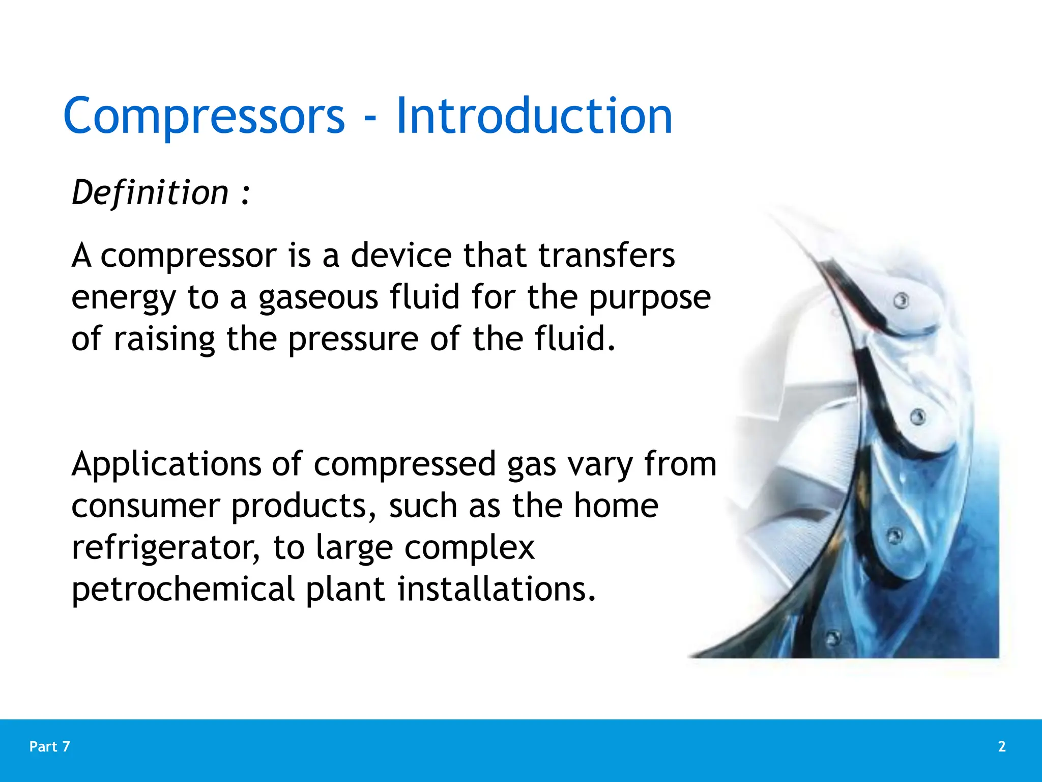
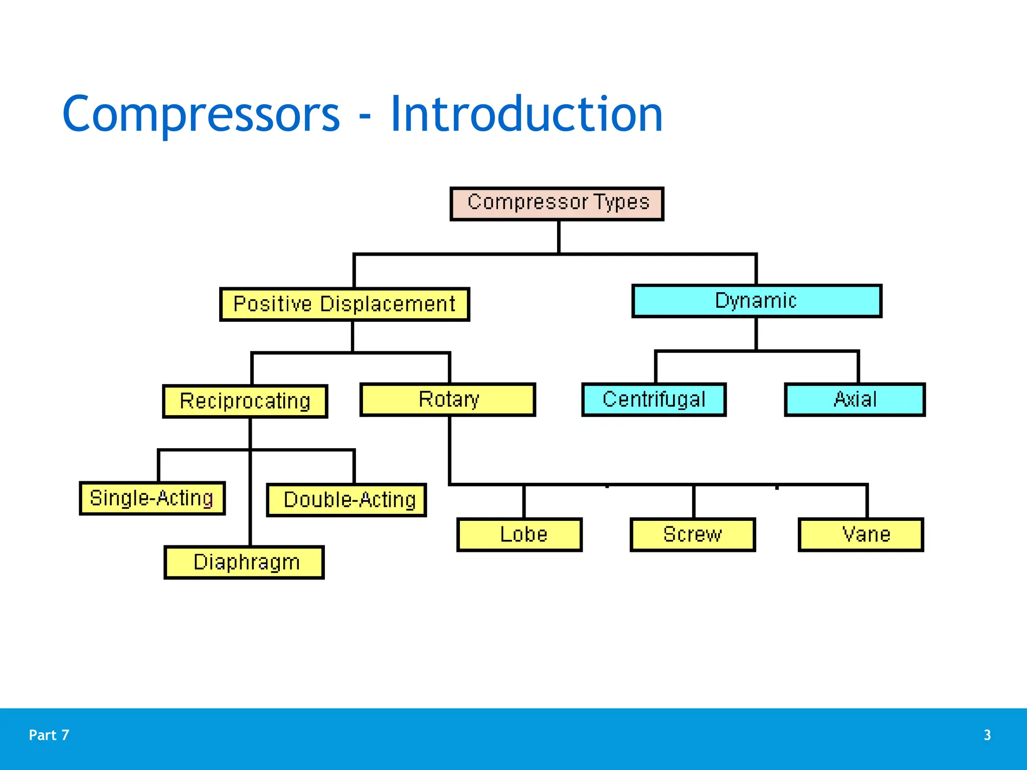
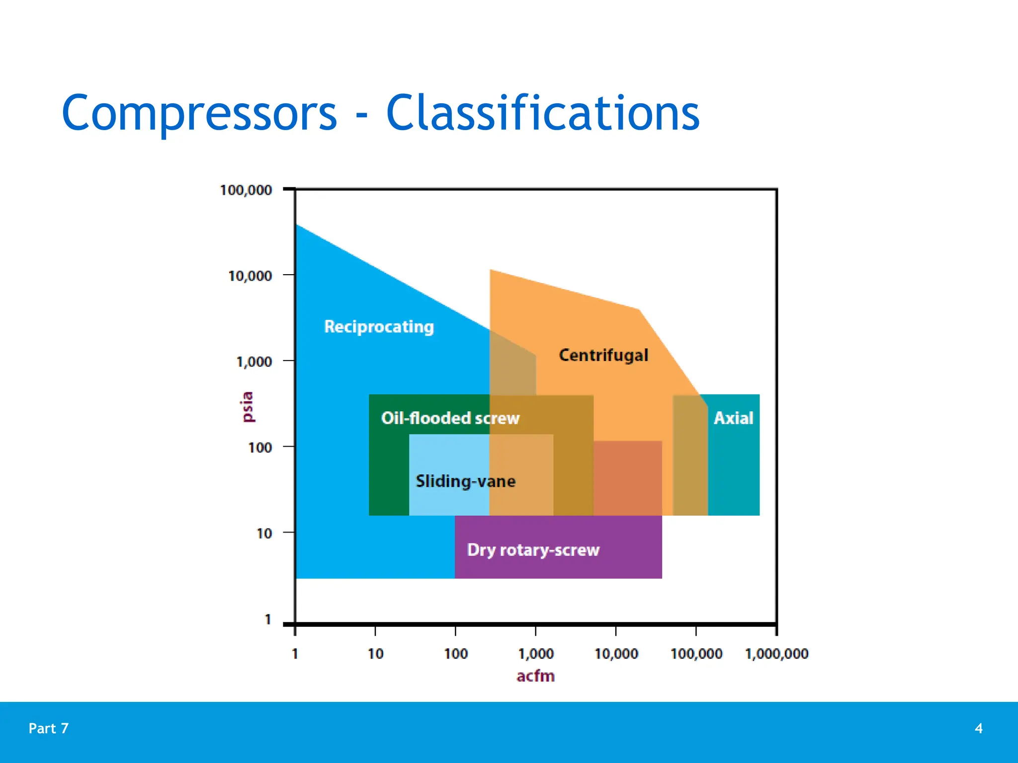
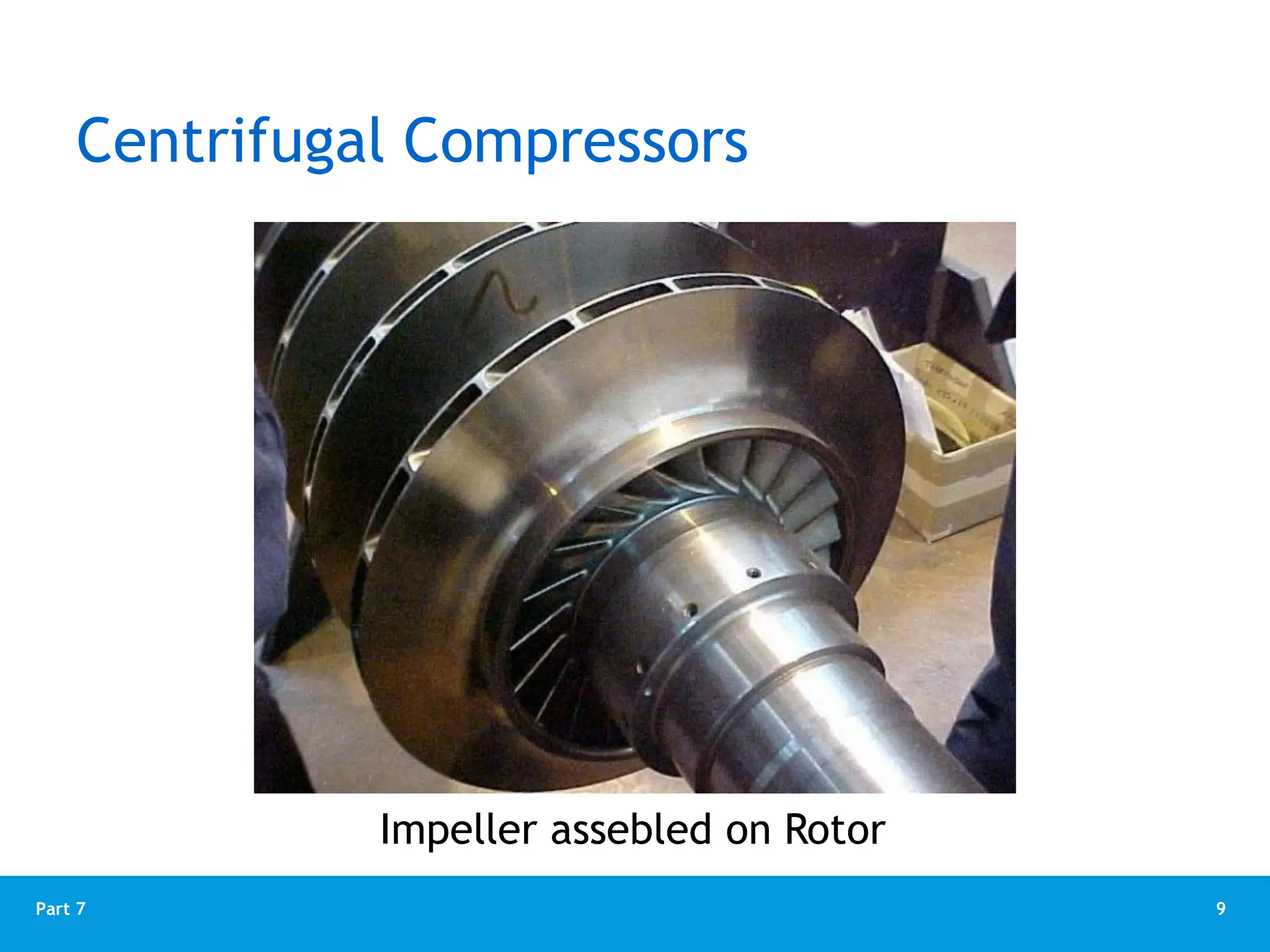
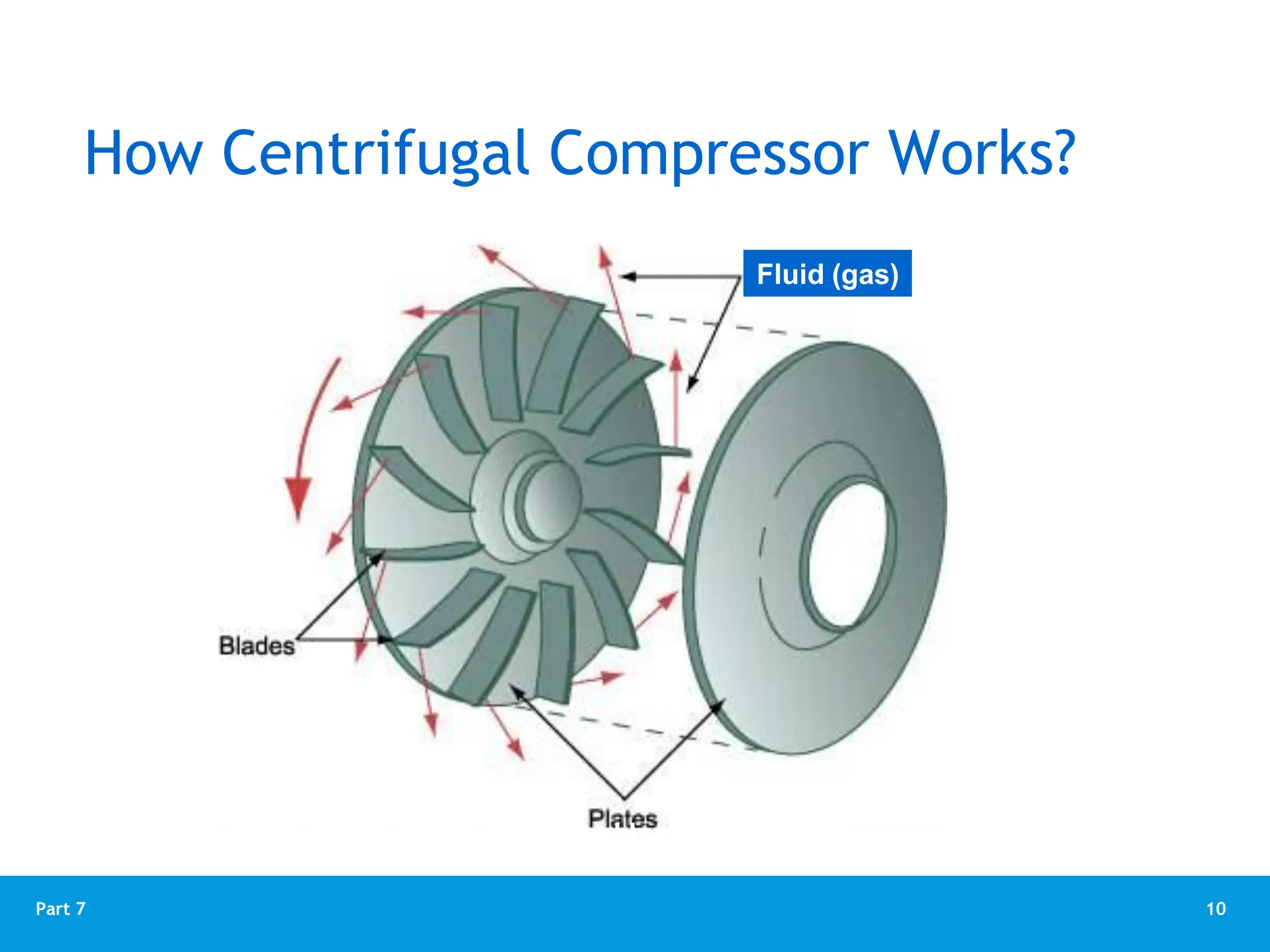
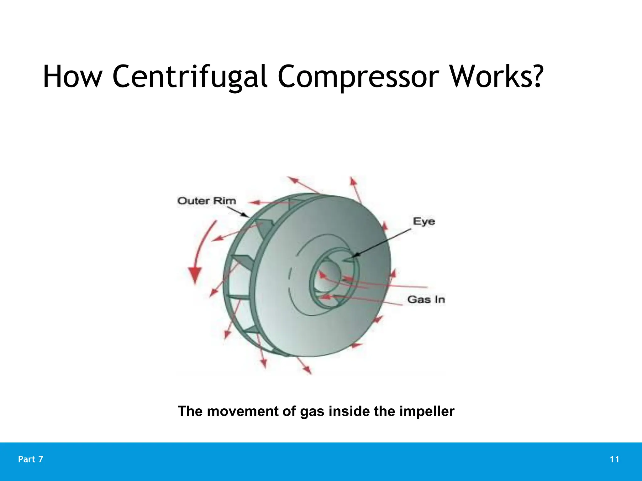
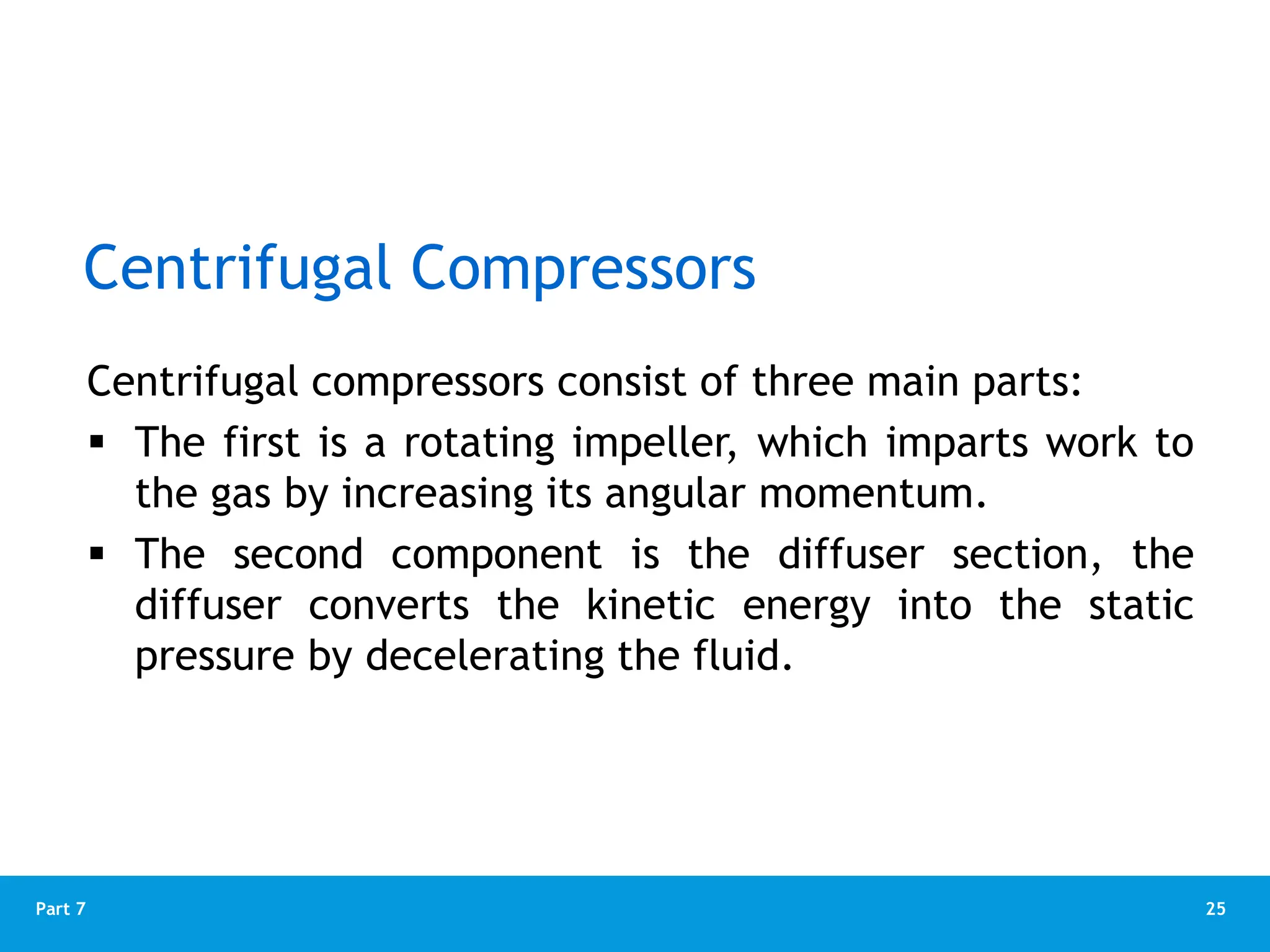
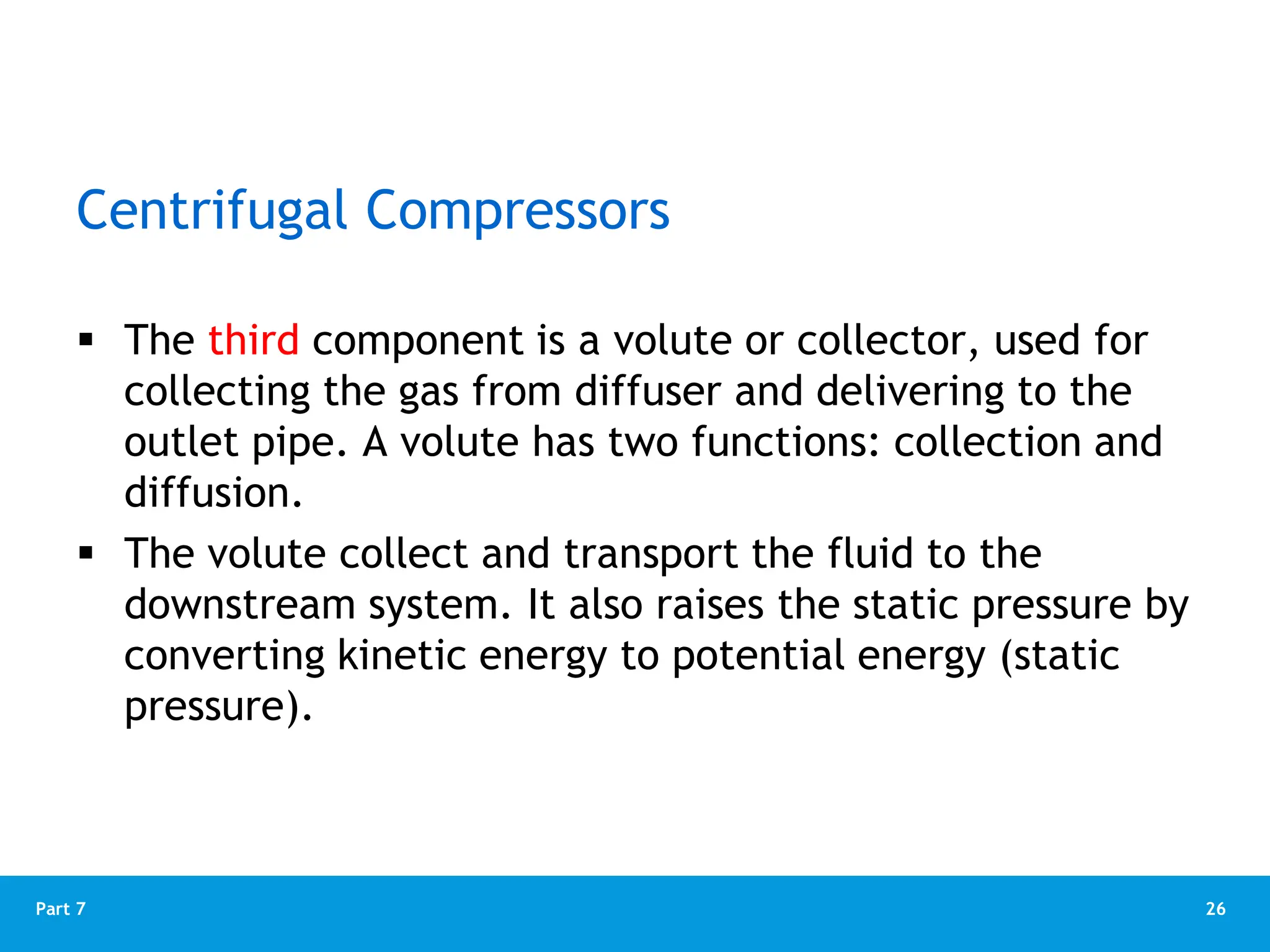
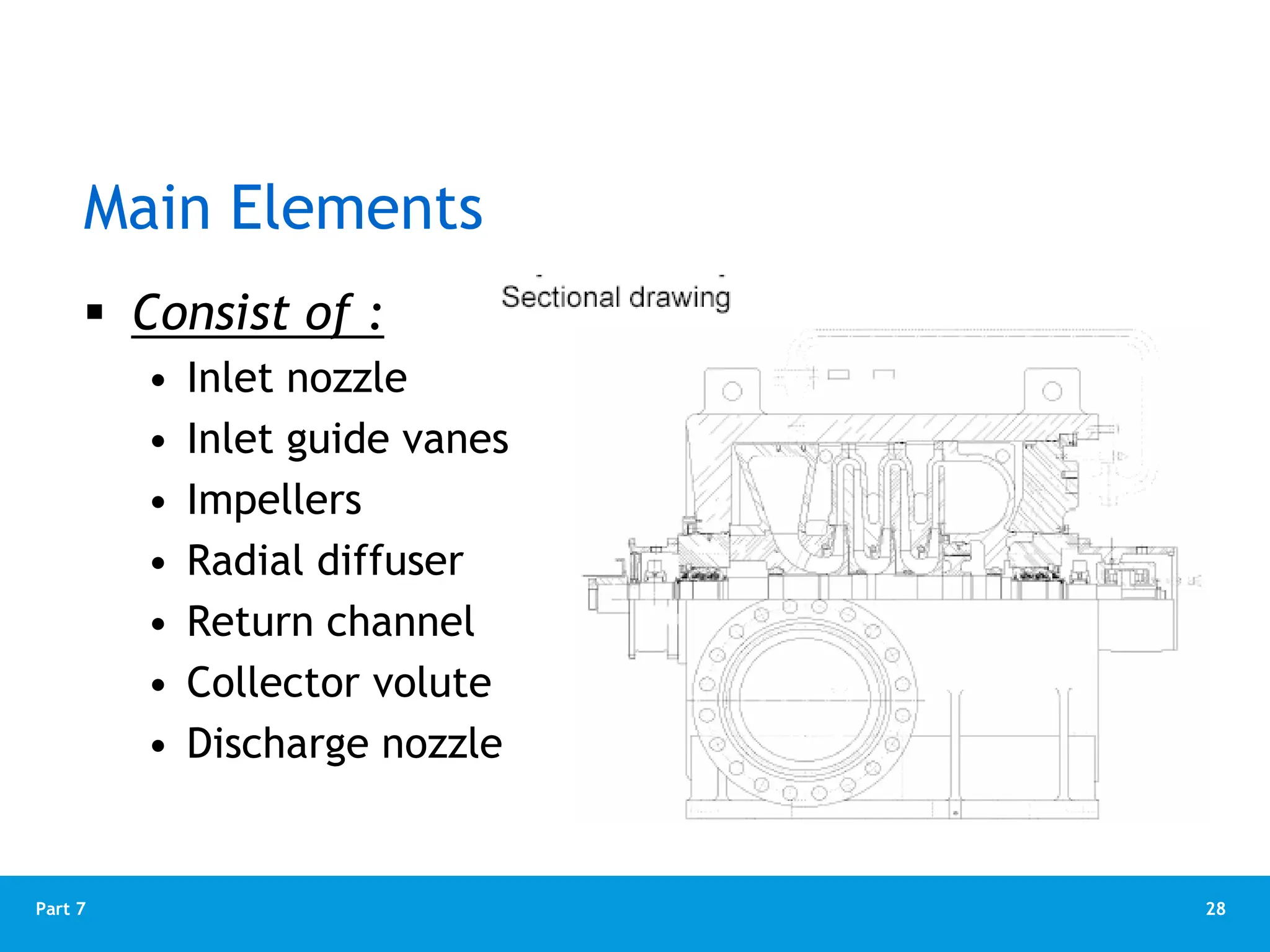
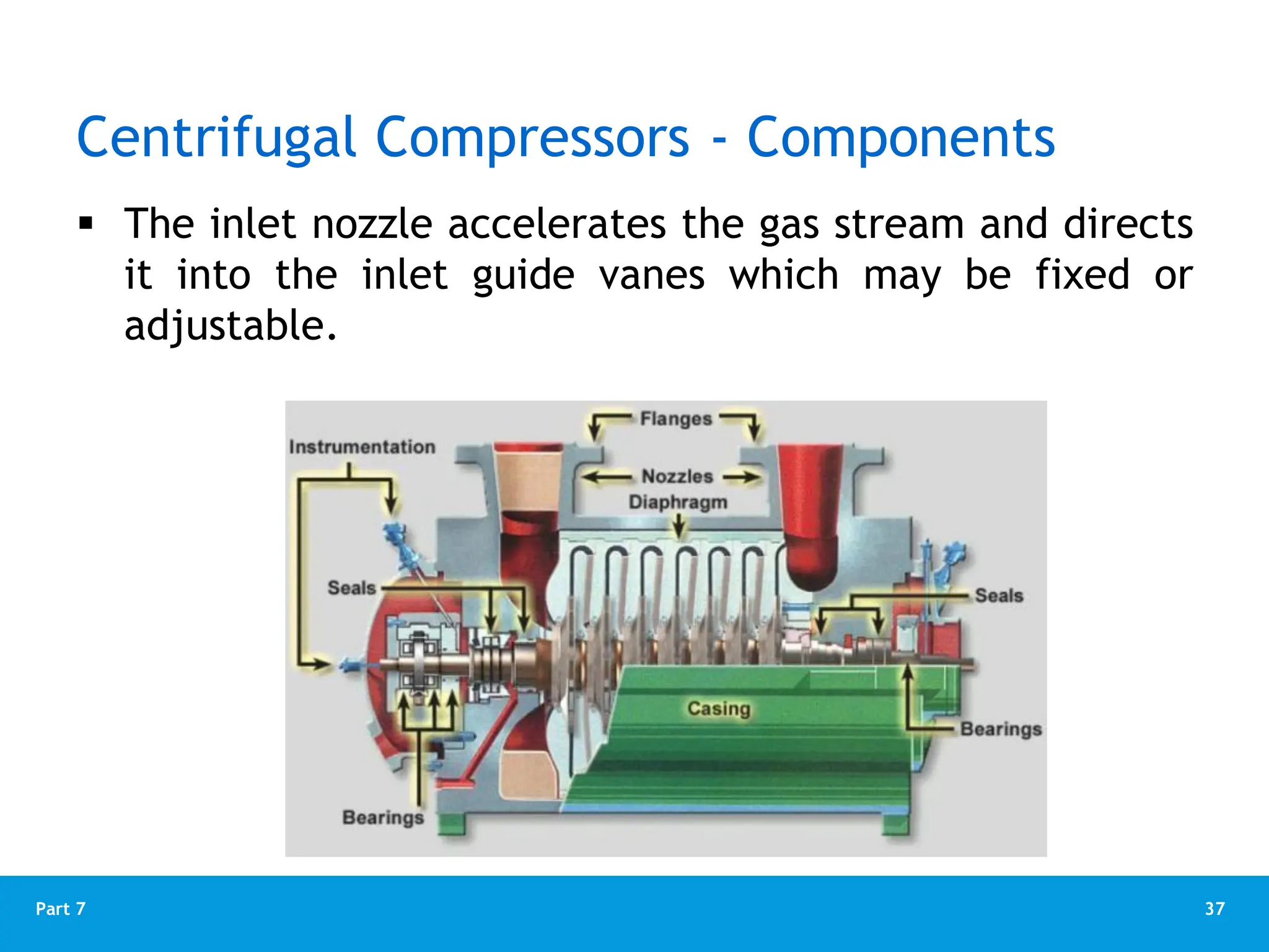
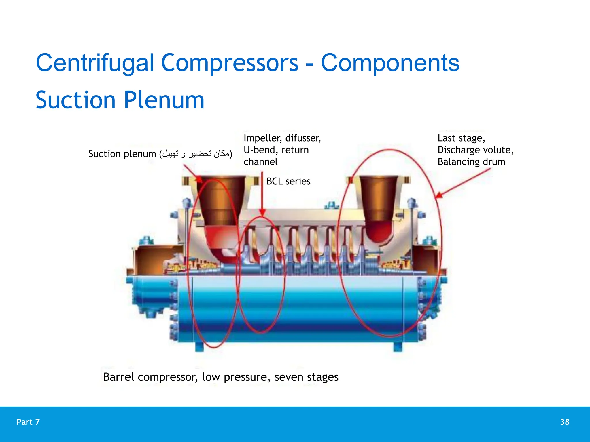
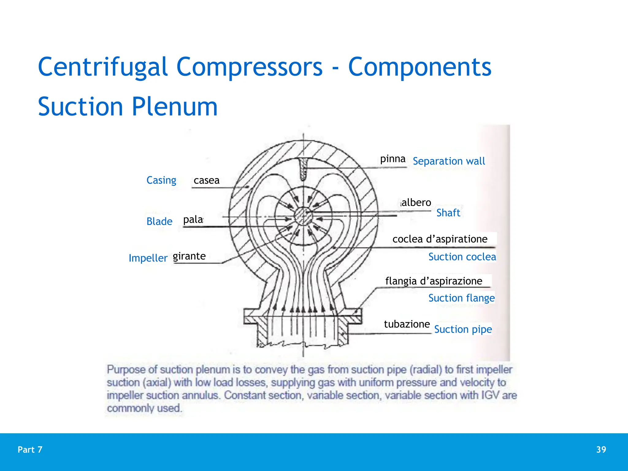
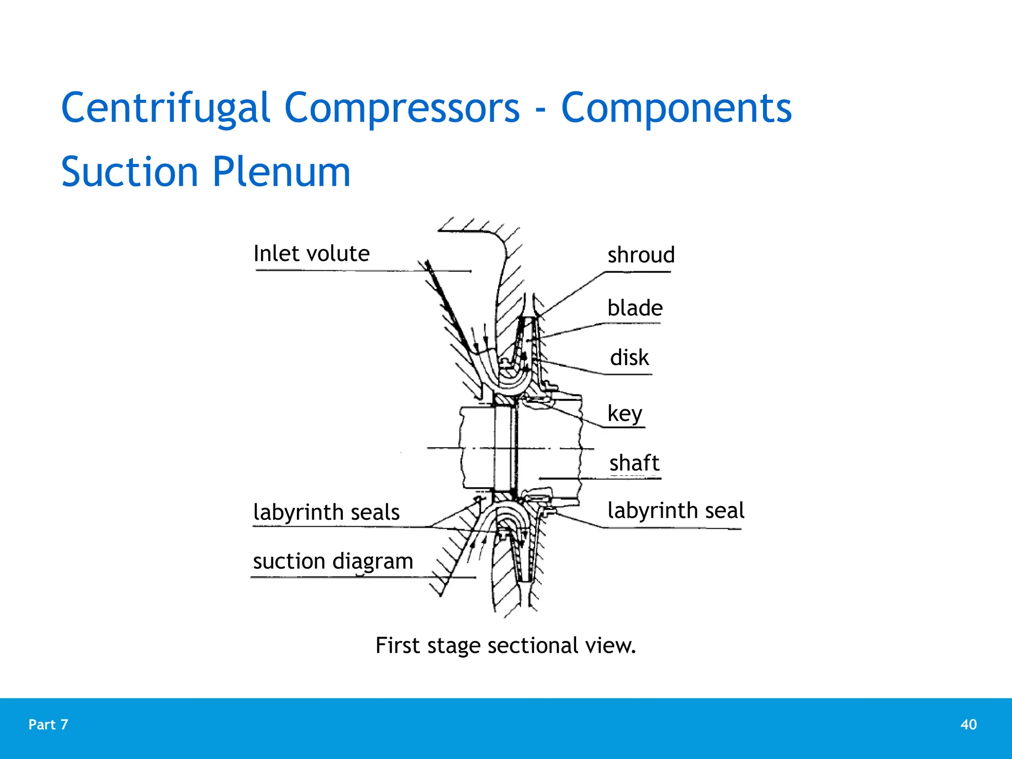
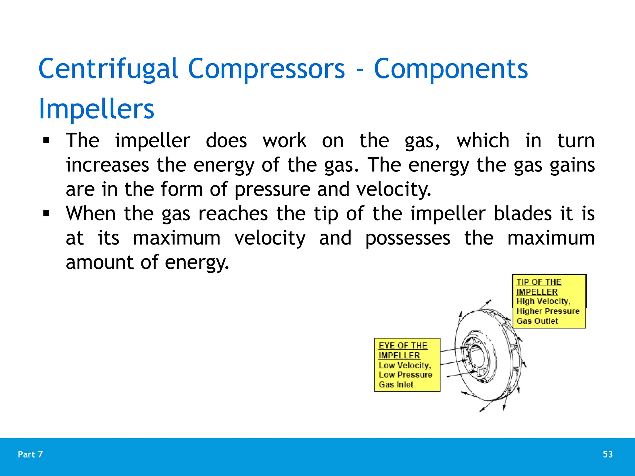
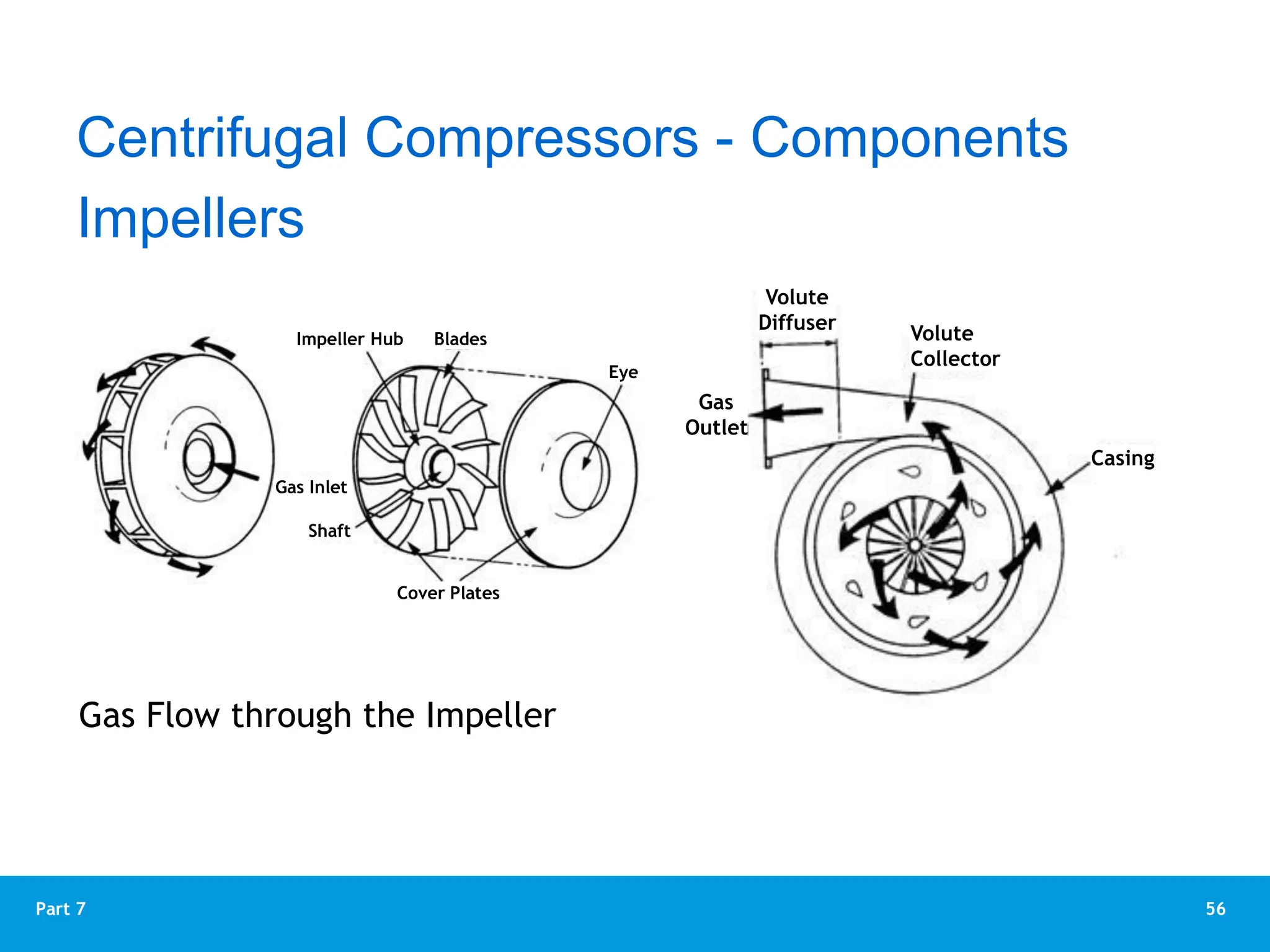
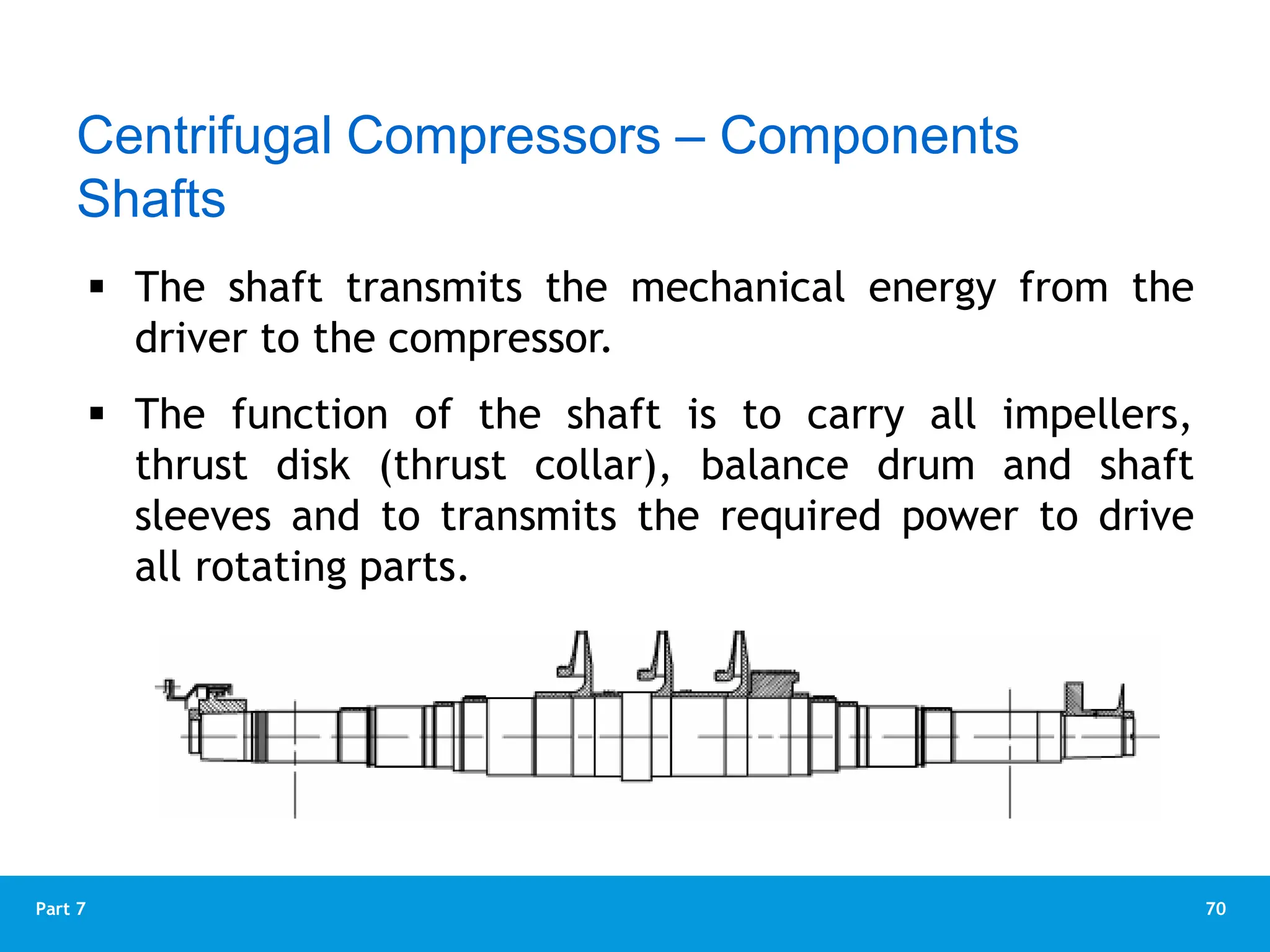
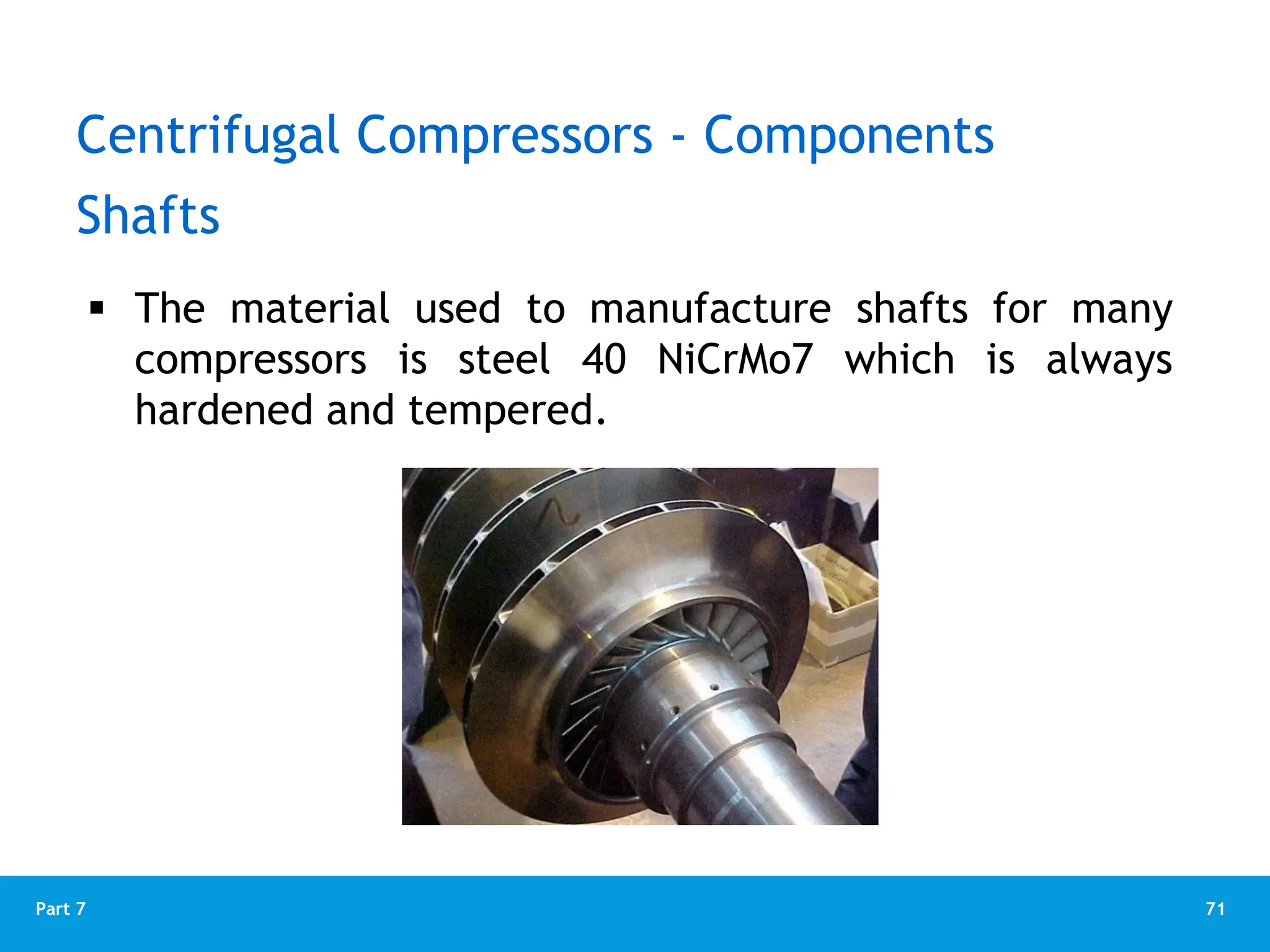
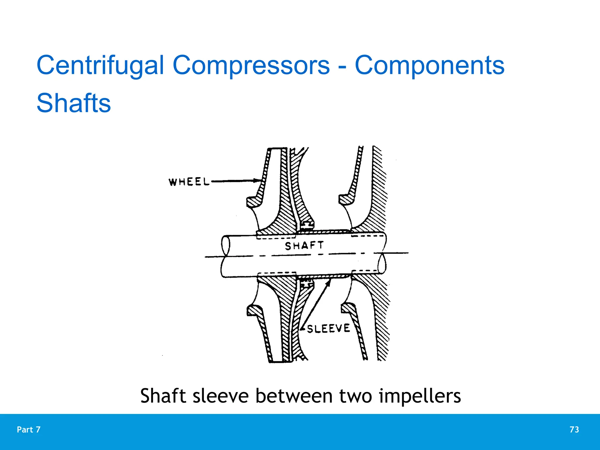
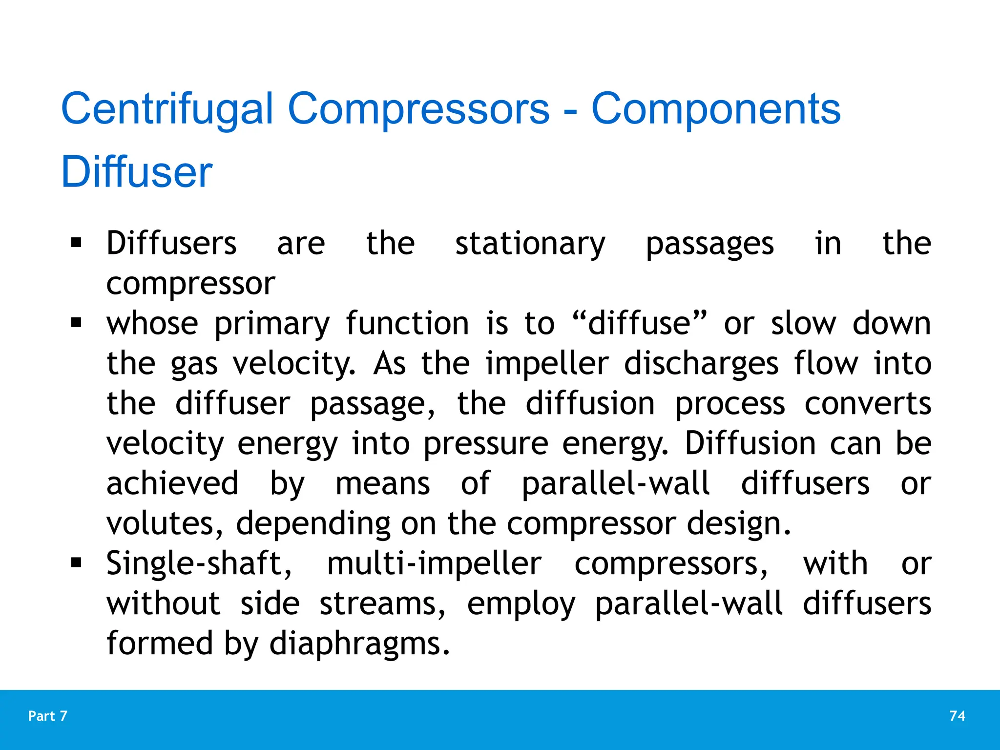
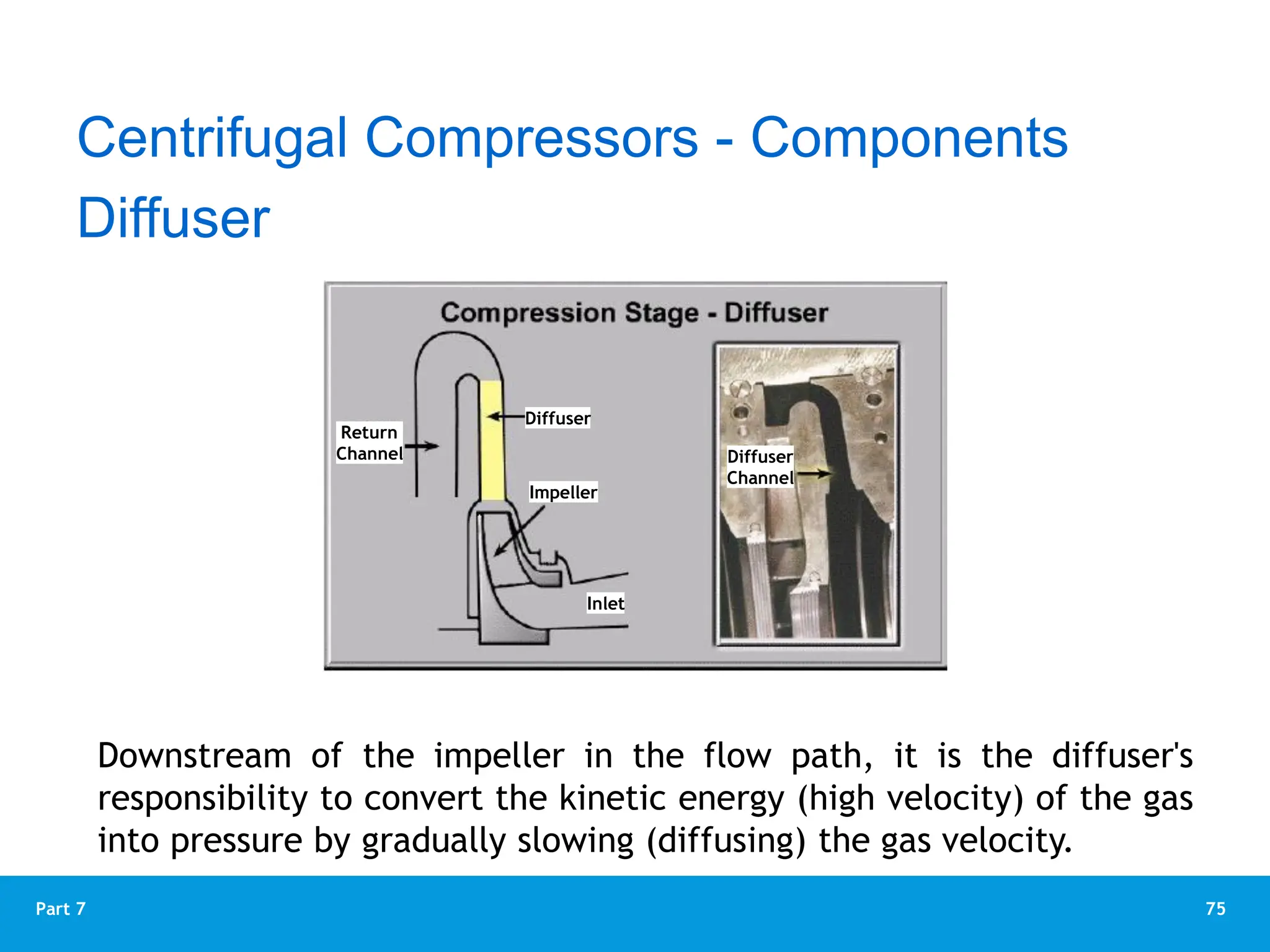
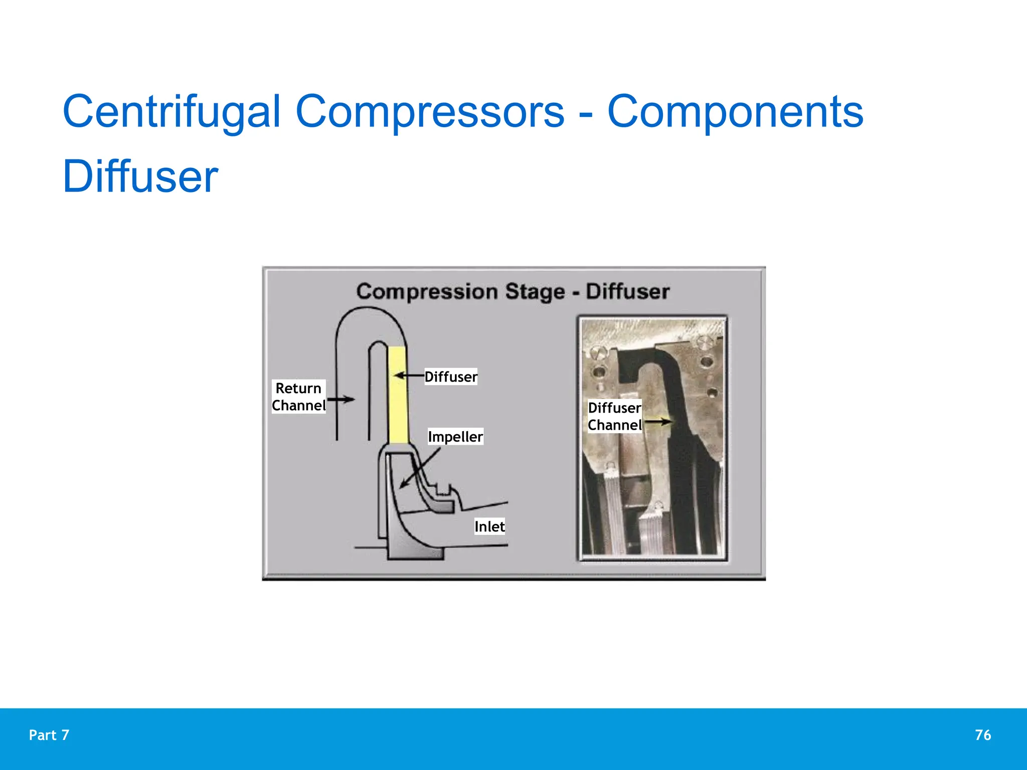
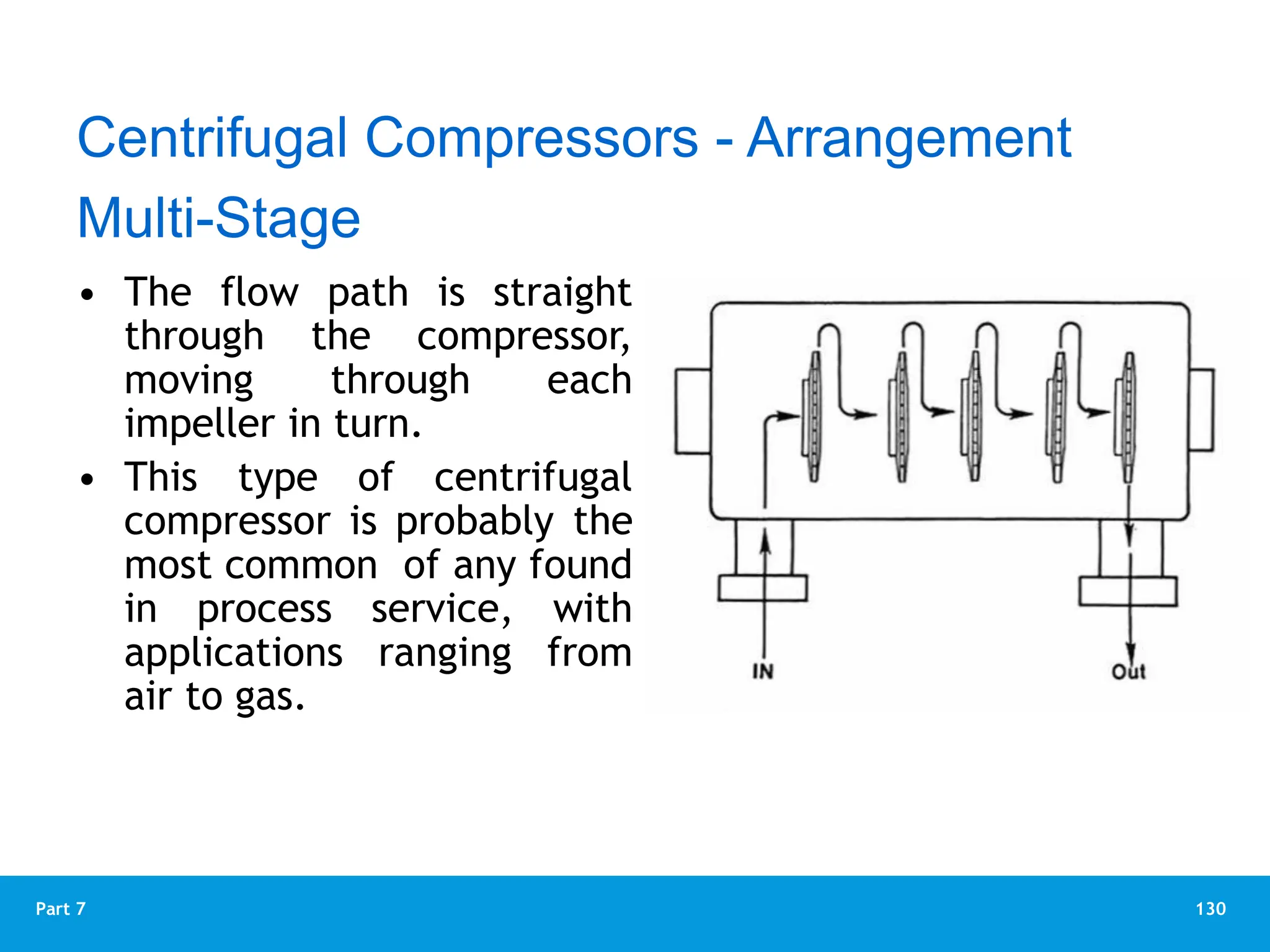
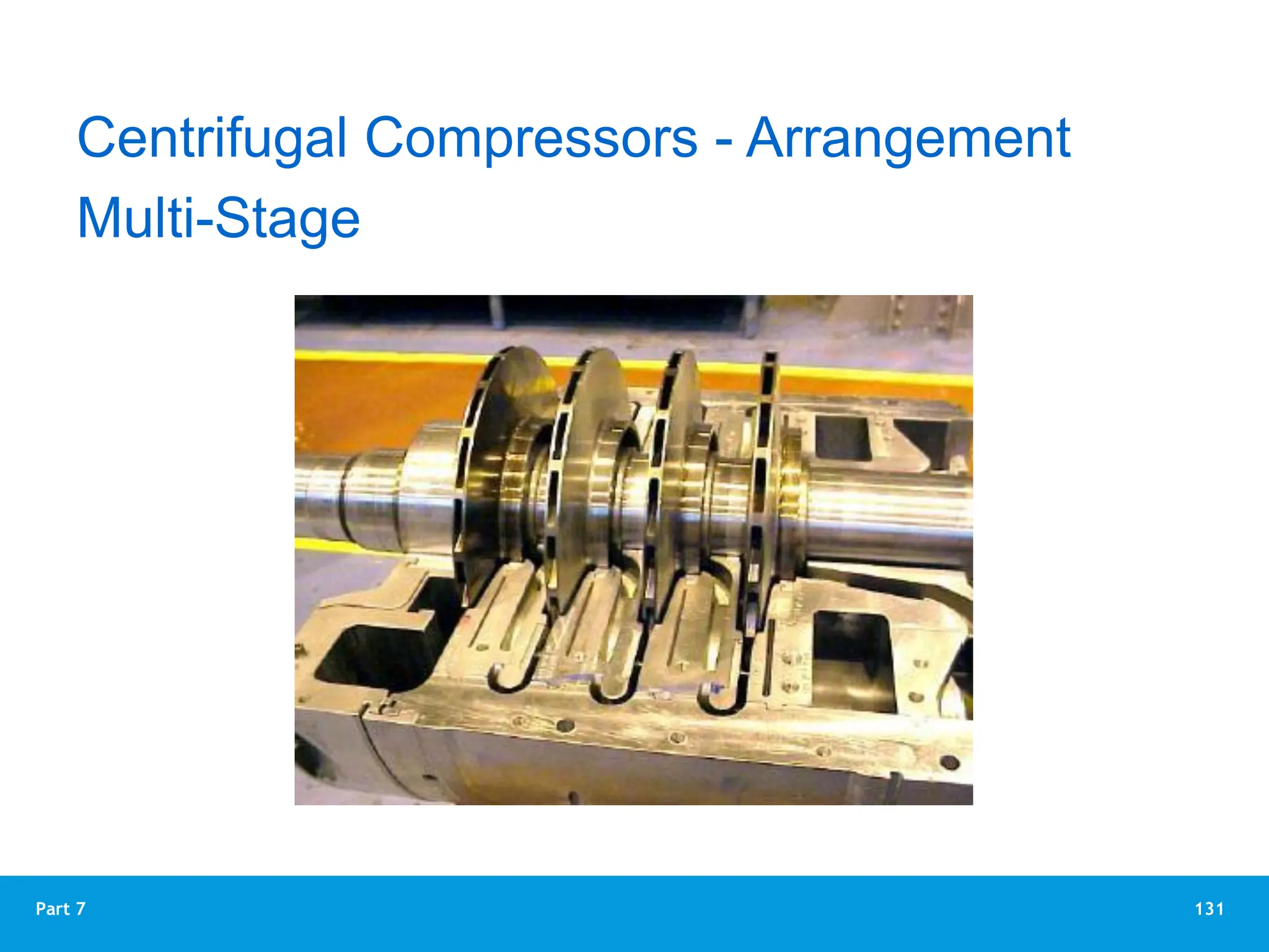
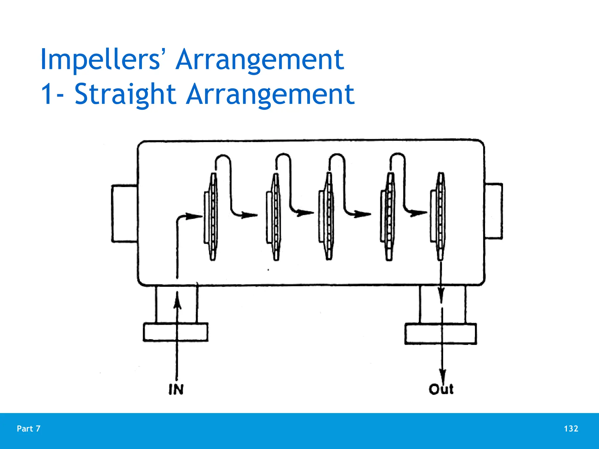
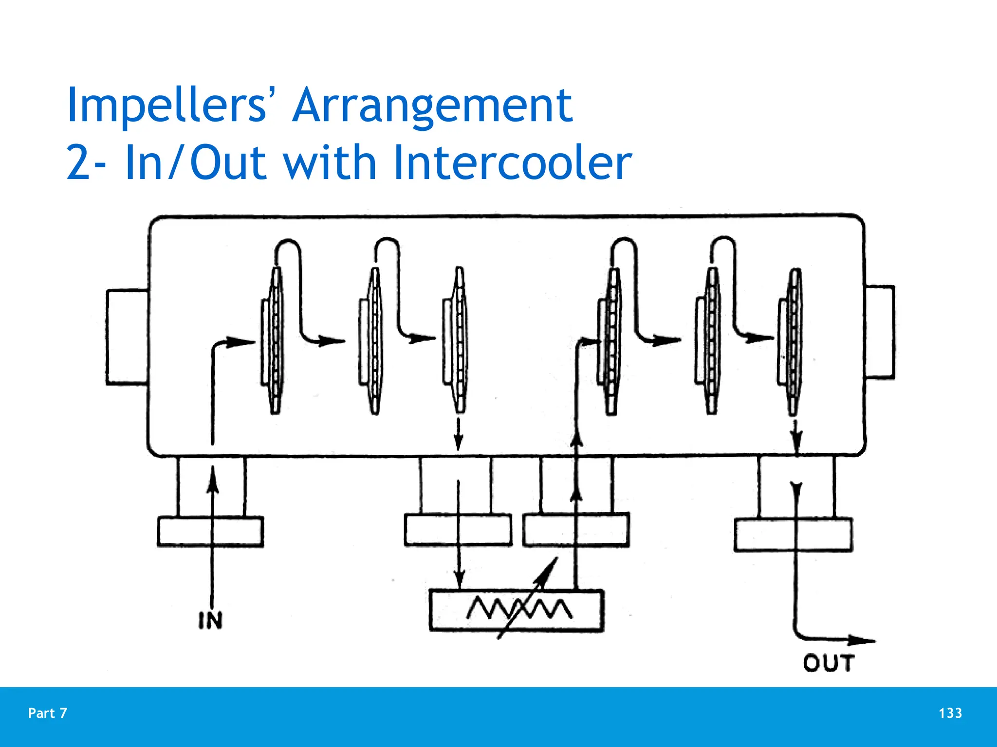
1
Part 7
Part 7
Compressors
2
Part 7
Definition :
A compressor is a device that transfers
energy to a gaseous fluid for the purpose
of raising the pressure of the fluid.
Applications of compressed gas vary from
consumer products, such as the home
refrigerator, to large complex
petrochemical plant installations.
Compressors - Introduction
3
Part 7
Compressors - Introduction
4
Part 7
Compressors - Classifications
5
Part 7
Centrifugal Compressor
Theory of Operation
6
Part 7
Centrifugal Compressor
 The most common type of compressor used today in
the oil and gas industry is the centrifugal compressor.
 The centrifugal air compressor is a dynamic
compressor which depends on a rotating impeller to
compress the air.
 It allows very high volumetric flow rates and good
compression ratio.
7
Part 7
 The operation of a centrifugal compressor is based on
centrifugal forces, which are outward and the
tangential forces, which are in the same direction of
rotation.
 Gas enters the compressor through the suction port,
which is directed by inlet guide vanes to the center of
the impeller.
 As the impeller rotates, gas rotates with it.
How Centrifugal Compressor Works?
8
Part 7
Centrifugal compressors compress gas by the mechanical action of
rapidly rotating impellers or bladed rotors that impart velocity and
pressure to the flowing gas. Velocity is further converted into
pressure in stationary diffusers.
How Centrifugal Compressor Works?
9
Part 7
Centrifugal Compressors
Impeller assebled on Rotor
10
Part 7
How Centrifugal Compressor Works?
Fluid (gas)
An impeller is made of two plates separated by curved blades
11
Part 7
How Centrifugal Compressor Works?
The movement of gas inside the impeller
12
Part 7
 This circular motion generates forces, which lift and
move the gas away from the center of the impeller.
 The forced gas enters the diffuser or volute passage at
a higher velocity and higher pressure.
 Suction is created at the eye (center) of the impeller
to draw more gas into the compressor.
 The impeller blades act like airplane wings, generating
a lift force on the gas that helps to force it from low
pressure, at the eye, to higher pressure at the outside
edge of the impeller.
How Centrifugal Compressor Works?
13
Part 7
 The centrifugal and lifting forces combined give the
gas two velocity components:
• Radial velocity is the speed of the gas moving
outward from the center towards the outside edge.
• Tangential velocity is the speed of the gas moving in
a straight line at right angle, to the radial velocity.
It is in the same direction as the outside edge is
moving.
 This combination of velocities increases the kinetic
energy of gas motion.
How Centrifugal Compressor Works?
14
Part 7
 As gas leaves the outside edge of the impeller, it
enters the diffuser.
 The diffuser is designed such that the flow area
increases as the gas leaves the impeller.
 This increased area allows the gas to slow down.
 As the velocity decreases, kinetic energy of the gas is
converted into pressure.
 The combination of centrifugal and tangential forces
together with the change in velocities produces the
final gas discharge pressure.
How Centrifugal Compressor Works?
15
Part 7
How Centrifugal Compressor Works?
 When the gas is at the tips of the impeller blades, it is
at maximum velocity.
 As the gas leaves the impeller, it is forced (through)
into a passage way called the diffuser.
 When the gas enters the diffuser, the impeller is not
acting directly on the gas.
 Due to the shape of the diffuser, the flow path of the
gas through the diffuser is in a larger spiral (the
following figure).
16
Part 7
How Centrifugal Compressor Works?
 Since the flow path is wider and there is no direct
action by the impeller blades, the velocity of the gas
decreases and its pressure increases.
 The diffuser converts the velocity into pressure.
 Gas passes from the diffuser into volute. In the
volute, the conversion from velocity to pressure
continues.
 A centrifugal compressor, by doing work on a gas
imparts both pressure and velocity to the gas, and
then the velocity of the gas is converted into pressure
within the compressor.
17
Part 7
Diffuser
Impeller
How Centrifugal Compressor Works?
18
Part 7
How Centrifugal Compressor Works?
The flow of gas from the impeller to diffuser and volute
19
Part 7
Gas Flow through a Compressor
Volute
Collector
Volute
Diffuser
Impeller
Inlet
Radial
Diffuser
Volute
Collector Stream Line
Spacer
20
Part 7
How Centrifugal Compressor Works?
 In a centrifugal
compressor, there is
a direct relationship
between impeller
speed, velocity,
pressure, and flow.
As the impeller speed
increases, velocity
increases. As velocity
increases, pressure
increases. As
pressure increases,
flow increases.
21
Part 7
How Centrifugal Compressor Works?
 Centrifugal compressors may be single-stage or
multistage, and the stages may be contained in one
casing or several different casings.
22
Part 7
Centrifugal Compressor Components
23
Part 7
Centrifugal Compressors
24
Part 7
Centrifugal Compressors
25
Part 7
Centrifugal compressors consist of three main parts:
 The first is a rotating impeller, which imparts work to
the gas by increasing its angular momentum.
 The second component is the diffuser section, the
diffuser converts the kinetic energy into the static
pressure by decelerating the fluid.
Centrifugal Compressors
26
Part 7
 The third component is a volute or collector, used for
collecting the gas from diffuser and delivering to the
outlet pipe. A volute has two functions: collection and
diffusion.
 The volute collect and transport the fluid to the
downstream system. It also raises the static pressure by
converting kinetic energy to potential energy (static
pressure).
Centrifugal Compressors
27
Part 7
Centrifugal Compressor Components
Compressor components can be divided into:
1. Compressor casing
2. Compressor rotor (shaft, impellers, balancing disc)
3. Compressor seals
4. Compressor bearings
28
Part 7
Main Elements
 Consist of :
• Inlet nozzle
• Inlet guide vanes
• Impellers
• Radial diffuser
• Return channel
• Collector volute
• Discharge nozzle
29
Part 7
Compressor Casing
 Compressor casing contains all internal components
It provides the suction nozzle and discharge nozzle
 There are two casing designs for centrifugal
compressors:
1. The horizontally split casing
2. Vertical split (radial split) casing compressor
 The following figures show these two designs
30
Part 7
A - Casing Split Method
Vertically Split
Good Seal
Difficult Maintenance
Horizontally Split
Bad Seal
Easy Maintenance
31
Part 7
A - Casing Split Method
Vertically Split
Good Seal
Difficult Maintenance
Horizontally Split
Bad Seal
Easy Maintenance
32
Part 7
Compressor Casing
1. The horizontally split casing is in two halves that are
bolted together to form tight enclosure.
 When the top half of the axial (horizontally) split
casing is removed, the entire internal component are
easily accessible.
33
Part 7
Compressor Casing
Axial (horizontal) split case compressor-6 stages
34
Part 7
Compressor Casing
2. Vertically split casing (or radial split casing), the
external casing has two removable end covers which
are bolted to the central (middle) barrel or external
middle casing (see the above figure).
 To reach the entire working component in this type,
the end covers has to be pulled and the internal
component (internal drum) must be removed from
the external casing.
35
Part 7
Compressor Casing
36
Part 7
Compressor Casing
Vertical split (radial split) casing compressor
37
Part 7
 The inlet nozzle accelerates the gas stream and directs
it into the inlet guide vanes which may be fixed or
adjustable.
Centrifugal Compressors - Components
38
Part 7
Suction Plenum
Centrifugal Compressors - Components
Suction plenum (
‫تهييل‬ ‫و‬ ‫تحضير‬ ‫مكان‬
)
Impeller, difusser,
U-bend, return
channel
Last stage,
Discharge volute,
Balancing drum
BCL series
Barrel compressor, low pressure, seven stages
39
Part 7
Suction Plenum
Centrifugal Compressors - Components
Casing
Blade
Impeller
casea
pala
girante
girante
pinna Separation wall
Shaft
albero
coclea d’aspiratione
Suction coclea
flangia d’aspirazione
Suction flange
tubazione
Suction pipe
40
Part 7
Suction Plenum
Centrifugal Compressors - Components
Inlet volute shroud
blade
disk
key
shaft
labyrinth seal
labyrinth seals
suction diagram
First stage sectional view.
41
Part 7
Suction Plenum
Centrifugal Compressors - Components
42
Part 7
Guide Vanes
 Compressor performance is affected by two factors.
These are:
1.The direction at which the gas enters the impeller
eye
2.The velocity of gas approach to the impeller eye
 If the gas can be made to enter the impeller in the
same direction as the impeller rotation then the
efficiency of the compressor will be increased.
43
Part 7
The Function of the Guide Vanes
 Guide vanes are designed to guide the flow of gas
efficiently into the suction eye of the impeller.
 Guide vanes may be either permanent or replaceable.
Usually, they are ahead of each impeller eye.
44
Part 7
The Function of the Guide Vanes
There are two designs of guide vanes:
 Variable guide vanes ahead of the 1st stage in some
designs not all (it is know also as adjustable inlet guide
vanes)
 Fixed guide vanes ahead of the 2nd, 3rd,4th stages
45
Part 7
The Function of the Guide Vanes
Fixed guide vanes
Impeller Guide Vanes
46
Part 7
The Function of the Guide Vanes
Fixed guide vanes
47
Part 7
The Function of the Guide Vanes
Adjustable Inlet Guide Vanes
Adjustable inlet guide vanes
48
Part 7
The Function of the Guide Vanes
 Adjustable guide vanes are usually available in single-
stage compressors and are sometimes used in the first
stage of a multi stage compressor.
 These vanes are adjusted automatically to control the
angle of gas flowing into the eye of the impeller.
 This controls the performance of a centrifugal
compressor and keeps it efficient over a wider
operating range.
49
Part 7
The Function of the Guide Vanes
Adjustable (variable) guide vanes on the suction of the first stage
50
Part 7
The Function of the Guide Vanes
Linkage elements associated with variable-inlet guide vanes
51
Part 7
 The impellers consist of two
discs, referred to as the disc
and shroud, connected by
blades which are shrunk onto
the shaft and held by either
one or two keys.
 The impeller pushes the gas
outwards raising its velocity
and pressure; the outlet
velocity will have a radial and
a tangential component.
Impellers
Centrifugal Compressors - Components
52
Part 7
Impeller Design
Consist of a series of blades and
attached to the shaft.
As the shaft rotates the centrifugal force generated by the rotating
impeller forces gas to flow outward.
53
Part 7
 The impeller does work on the gas, which in turn
increases the energy of the gas. The energy the gas gains
are in the form of pressure and velocity.
 When the gas reaches the tip of the impeller blades it is
at its maximum velocity and possesses the maximum
amount of energy.
Impellers
Centrifugal Compressors - Components
54
Part 7
 The part of the centrifugal compressor that moves the
gas is the impeller.
 The gas enters through the eye of the impeller and as
the impeller rotates it moves the gas towards the
outer rim of the impeller.
 Movement of the gas towards the outer rim of the
impeller causes the gas velocity to increase. This
increase in velocity away from the eye creates a low-
pressure area at the-eye of the impeller causing
suction, which allows more gas to enter.
Impellers
Centrifugal Compressors - Components
55
Part 7
 The impeller does work on the gas, which in turn
increases the energy of the gas. The energy the gas
gains are in the form of pressure and velocity.
 When the gas reaches the tip of the impeller blades it
is at its maximum velocity and possesses the maximum
amount of energy.
Impellers
Centrifugal Compressors - Components
56
Part 7
Gas Flow through the Impeller
Impellers
Centrifugal Compressors - Components
Gas Inlet
Shaft
Impeller Hub Blades
Eye
Cover Plates
Volute
Diffuser
Volute
Collector
Casing
Gas
Outlet
57
Part 7
 As the gas leaves the impeller it is thrust into a
passageway called the diffuser. As the flow area in the
diffuser is larger than that in the impeller, the velocity
of the gas begins to decrease. This causes the gas
pressure to increase. The diffuser converts the velocity
of the gas to increased pressure.
 From the radial diffuser the gas passes into the volute
collector and finally the volute where the transition of
energy from velocity to pressure continues.
Impellers
Centrifugal Compressors - Components
58
Part 7
Impellers
Centrifugal Compressors - Components
59
Part 7
 The impeller delivers the energy to the gas. Approx.
two thirds of this energy is transformed into pressure in
the impeller itself and the remaining one third is
transformed into pressure in the diffuser. Impellers are
generally closed type. Open impellers are applied only
for overhung compressors. Diffuser is free vortex type
(just two parallel walls) for multistage compressors and
may be of the vaned type for overhung compressors.
Impellers
Centrifugal Compressors - Components
60
Part 7
The Compressor Rotor
Centrifugal compressor rotor assembly (5 stages)
61
Part 7
The Compressor Rotor
Single stage rotor (Impeller fixed to the shaft)
62
Part 7
The Compressor Rotor
1. Impellers
 The impeller increases the velocity of a gas by
rotating about the center line and causing the gas to
move from the inlet (impeller suction eye) to the tip
of the impeller (or discharge).
 The difference in the distance from the axis of
rotation of the impeller inlet and the impeller
discharge causes the increase in kinetic energy.
63
Part 7
The Compressor Rotor
There are three different
designs of impeller are
commonly used.
Compressor impellers
Open impeller
Used for small heads and small
to large flow in single stage
compressor only
Open Impeller
Semi-open impeller
Used for large flow, usually in
single stage compressors, or as
the first stage in multi-stage
Semi-open Impeller
Closed impeller
Used in multi-stage compressors
Closed Impeller
64
Part 7
MAIN PARTS
Impeller Types
Open
Impeller
Semi-open
Impeller
Closed
Impeller
65
Part 7
The Compressor Rotor
Impeller of centrifugal compressor Centrifugal compressor impeller
(Semi-open impeller) (semi-open impeller)
66
Part 7
Semi – Open Impeller
Impellers
Centrifugal Compressors - Components
67
Part 7
Impellers
Centrifugal Compressors - Components
68
Part 7
Impellers
Centrifugal Compressors - Components
Closed
impeller
design
69
Part 7
Impellers
Centrifugal Compressors - Components
High-pressure, vertically split centrifugal compressor
70
Part 7
Rotor
 The shaft transmits the mechanical energy from the
driver to the compressor.
 The function of the shaft is to carry all impellers,
thrust disk (thrust collar), balance drum and shaft
sleeves and to transmits the required power to drive
all rotating parts.
Centrifugal Compressors – Components
Shafts
71
Part 7
 The material used to manufacture shafts for many
compressors is steel 40 NiCrMo7 which is always
hardened and tempered.
Shafts
Centrifugal Compressors - Components
72
Part 7
Shaft Sleeves
Shaft sleeves are used to:
1. As spacer between different impellers on the shaft.
2. To afford wearing surfaces for inter-stage seals. In
certain instances shaft sleeves protect the shaft
from corrosive elements in the gas.
3. Sleeves are also used in conjunction with shaft seals
and occasionally for bearing surfaces, as in the case
of shaft made of certain stainless steels.
Shafts
Centrifugal Compressors - Components
73
Part 7
Shaft sleeve between two impellers
Shafts
Centrifugal Compressors - Components
74
Part 7
Diffuser
 Diffusers are the stationary passages in the
compressor
 whose primary function is to “diffuse” or slow down
the gas velocity. As the impeller discharges flow into
the diffuser passage, the diffusion process converts
velocity energy into pressure energy. Diffusion can be
achieved by means of parallel-wall diffusers or
volutes, depending on the compressor design.
 Single-shaft, multi-impeller compressors, with or
without side streams, employ parallel-wall diffusers
formed by diaphragms.
Centrifugal Compressors - Components
75
Part 7
Diffuser
Downstream of the impeller in the flow path, it is the diffuser's
responsibility to convert the kinetic energy (high velocity) of the gas
into pressure by gradually slowing (diffusing) the gas velocity.
Centrifugal Compressors - Components
Return
Channel
Diffuser
Impeller
Inlet
Diffuser
Channel
76
Part 7
Diffuser
Centrifugal Compressors - Components
Return
Channel
Diffuser
Impeller
Inlet
Diffuser
Channel
77
Part 7
Diffuser
Centrifugal Compressors - Components
78
Part 7
Diffuser
The diffusers of centrifugal compressors can be divided to two classes:
vaneless and vaned diffusers. Vaneless diffusers have a wider flow range
but lower pressure recovery and efficiency, whereas vaned diffusers have
higher pressure recovery and efficiency, but narrower flow range.
Centrifugal Compressors - Components
Vaneless diffuser
Impeller
Vaned diffuser
impeller
79
Part 7
Diffuser
 Vaneless diffusers were the most widely-used style
in industrial centrifugal until the late 1980’s when
some Original Equipment Manufacturers (OEMs)
began applying a vaned diffuser design.
 Vaneless diffusers contain no vanes. Conversely,
vanned diffusers contain one or more rows of vanes.
In general, vaneless diffusers offer the widest flow
range because there are no vanes to interfere with
the gas as it passes through the diffuser. However,
the static pressure recovery in vaneless diffusers is
not as high as in their vaned counterparts.
Centrifugal Compressors - Components
80
Part 7
Vaned Diffuser
Diffuser
Centrifugal Compressors - Components
81
Part 7
Diffuser
Vaned diffusers may improve stage
efficiency (up to 3-5%) but generally
decrease compressor flow range
Centrifugal Compressors - Components
82
Part 7
U Bend and Return Channel
U-bend and return channel lead gas to the next stage of a multistage
compressor. Return channel is bladed and has the purpose to de-swirl the gas
leading it to next stage impeller suction annulus axially No transformation of
kinetic energy in to pressure takes place in the return channel.
Centrifugal Compressors - Components
83
Part 7
Diaphragms
 Compressor diaphragms are stationary inserts that
must direct the process gas into successive impellers.
It should be noted that diffusers, return bends, and
return passages all constitute volumes created by the
walls of the diaphragms and casing.
Return passages
To the next stage
Diaphragm
Compressor casing
Inlet guide vanes
For the next stage
84
Part 7
Diaphragms
 Diaphragms are used in multi-stage centrifugal
compressor as partition between the different stages
(impellers) to create a passage for the gas from one
stage to the next one.
85
Part 7
Impeller
Diffuser Cross-Over
Return
Channel
Eye Seal
Diaphragm
Seal
CASING
Diaphragms
86
Part 7
Diaphragms
Diaphragm in the lower half of the casing
87
Part 7
Purpose of the discharge volute is to convey the gas from last
stage diffuser exhaust to the discharge pipe by recovering into
pressure its kinetic energy with minimum losses.
Discharge Volute
Centrifugal Compressors - Components
88
Part 7
Balancing Drum
 The balance drum is mounted on the shaft after the end
impeller. It serves to balance the total thrust produced
by the impellers. Having end impeller delivery pressure
on one side of the drum, compressor inlet pressure is
applied to the other by an external connection. In this
way, gas pressures at both ends of the rotor are roughly
balanced.
Centrifugal Compressors - Components
89
Part 7
Balancing Drum
• On the disc side, the impeller is exposed to discharge pressure
and on the other side partly to the same pressure and partly to
suction pressure. Thus a thrust force is created towards suction.
Centrifugal Compressors - Components
90
Part 7
Balancing Drum
 Thrust force is always developed in the impeller with a resultant
force in the direction of the inlet.
thrust force thrust neutralization
Centrifugal Compressors - Components
Direction
of Thrust
Direction
of Thrust
Direction
of Thrust
Flow
Suction
Pressure
Suction
Pressure
Flow
Discharge
Pressure
Suction
Pressure
91
Part 7
Balancing Drum
Centrifugal Compressors - Components
Axial load
Last impeller
Balancing Drum
Suction
Pressure
Discharge
Pressure
Hub Side Disk Side
Axial Force
92
Part 7
Balancing Drum
 The purpose of the balancing drum is to counteract the
net thrust which the impellers exert to move the rotor
axially towards the gas inlet end of the compressor
(low pressure end).
Centrifugal Compressors - Components
93
Part 7
Balancing Drum
 This counteraction is accomplished by venting the
outboard side of the drum via a balance pipe to the
compressor suction end.
 Since the inboard side of the piston is exposed to
compressor discharge pressure, then a pressure
differential is created across the piston, which acts to
balance the impeller thrust.
 The impeller thrust is slightly greater than that of the
balancing piston and the difference is taken up by the
thrust bearing.
Centrifugal Compressors - Components
94
Part 7
 Centrifugal compressor rotors are normally built with a
balancing drum installed at the discharge end.
 When the compressor is running, there is axial force
acting on the impeller forcing it towards the suction
side.
 In multi-stage centrifugal compressor, if the impellers
are arranged in one direction, the final resultant force
which is acting on the shaft will be very high.
Balancing Drum
Centrifugal Compressors - Components
95
Part 7
 To cut down this axial force due to pumping, the
designers use balance drum.
 The balance drum is just cylindrical drum (or disc)
fixed to the compressor shaft and rotate with it.
 One side of the balance drum is subjected to suction
pressure and the other side is subjected to discharge
pressure.
Balancing Drum
Centrifugal Compressors - Components
96
Part 7
 The pressure difference at the balancing drum causes
(creates) axial force equal to and in opposite direction
to the axial load which is acting on the rotor due to
pumping action (see the following figure on the next
page).
 These two forces balance each other because they are
equal and exerted in apposite directions.
 As a result the shaft does not have much axial force in
either direction (see the following figure).
Balancing Drum
Centrifugal Compressors - Components
97
Part 7
Balancing drum and balance line
Balancing Drum
Centrifugal
Compressors –
Components
SUCTION
BALANCE
LINE DISCHARGE
GAGE
BALANCING
DRUM
DISCHARGE
PRESSURE
SUCTION
PRESSURE
BALANCING
DRUM
LABYRINTH SEAL
IMPELLER
SUCTIO
PRESSURE
DISCHARGE
PRESSURE
98
Part 7
Balance drum
Last stage
impeller
Balancing Drum
Centrifugal Compressors - Components
99
Part 7
Balance drum
Last stage
impeller
Balancing drum
Balancing Drum
Centrifugal Compressors - Components
100
Part 7
Balance drum
Multi-stage centrifugal
compressor- 6 stages with
balancing drum
Centrifugal Compressors – Components
Balancing Drum
101
Part 7
 Due to the pressure rise across successive compression
stages, seals are required at the impeller eye and rotor
shaft to prevent gas backflow from the discharge to
inlet end of the casing.
 Internal labyrinths, are used along the gas path to
minimize leakage between stages, along the balance
piston, and ahead of the seals separating compressor
internals from compressor bearings. Internal leakage
from regions of higher pressure to regions of lower
pressure contributes to compressor inefficiency.
Inter-stage Seals
Centrifugal Compressors - Components
102
Part 7
Centrifugal Compressors - Components
Inter-stage Seals
103
Part 7
Centrifugal Compressors - Components
Inter-stage Seals
104
Part 7
Labyrinth Seal
1. Labyrinth seal does not stop gas leakage 100%.
2. It minimizes the leakage to lower limits. For this
reason it is used inside the compressor to minimize
the leakage from one stage to another i.e. from high
pressure area to low pressure area.
3. The leakage rate depends upon the labyrinth seal
clearance and the pressure difference on both sides of
the seal.
Centrifugal Compressors - Components
Inter-stage Seals
105
Part 7
4. Labyrinth seal materials must be:
 Softer than the rotor material.
 Able to resist chemical attack from the gas being
pumped (compatible).
 Can’t create any spark if rubbing happen.
Centrifugal Compressors - Components
Inter-stage Seals
106
Part 7
Each both ends of centrifugal compressor has two sealing
areas, They are two shaft seals on both ends of the shaft
are used to separate the gas stream from the bearing
area (chamber) and from the surrounding environment.
Particular care must be taken when the gas is
combustible or toxic.
Centrifugal Compressors - Components
Inter-stage Seals
107
Part 7
Shaft seals are used to achieve one of the following:
1. Reduce or prevent in-leakage of gas (example:
preventing air or oil vapour from entering the gas
stream) i.e. from outside the compressor casing as high
pressure area to inside the compressor casing as low
pressure area.
2. Reduce or prevent out-leakage of gas from high
pressure areas to the atmosphere (discharge end of the
compressor). Example: If the gas stream is chlorine,
which is very toxic.
3. Reduce or prevent both in-leakage and out-leakage.
108
Part 7
Centrifugal Compressors - Components
Shaft Seals
The primary purpose of compressor shaft seals is to
avoid:
 Gas leakage into the atmosphere. Both safety and loss
of revenue are at issue here.
 The American Petroleum Institute, in its Standard API-
617, describes five generic (
‫عام‬
) types of seals:
labyrinth, restrictive carbon rings seal, mechanical
contact, liquid film, and “dry” gas seals. Mechanical
contact and liquid film seals employ liquid as the
sealing medium. Process gas or a buffered inert gas
medium alone is used in the other three seal types.
109
Part 7
Centrifugal Compressors - Components
Shaft Seals
Labyrinth seals
110
Part 7
Centrifugal Compressors - Components
Shaft Seals – Labyrinth Seal
Labyrinth seals
Labyrinth Seals
Generally used in air or nitrogen applications
Or where slight leakage to the atmosphere
Is tolerable.
111
Part 7
Labyrinth seal
Centrifugal Compressors - Components
Shaft Seals – Labyrinth Seal
112
Part 7
 In this seal there are several carbon rings around the
shaft.
Centrifugal Compressors - Components
Shaft Seals – Restrictive Seal
113
Part 7
 The rings are held in position around the shaft by
stationary ring cups. These rings do not contact the
shaft.
 The carbon ring elements can either be solid, or
segmented.
 When using a segmented carbon ring, it is usually
enclosed with a garter spring to maintain the ring.
Furthermore, segmented carbon rings are generally
used where it is desired to have a split element to ease
maintenance and / or replacement.
Centrifugal Compressors - Components
Shaft Seals – Restrictive Seal
114
Part 7
The carbon rings
Centrifugal Compressors - Components
Shaft Seals – Restrictive Seal
Garter Spring = ‫الرباط‬ ‫سوستة‬
115
Part 7
Centrifugal Compressors - Components
Shaft Seals
Mechanical Seals
Oil or Water
116
Part 7
It is suitable for high pressures.
 In this type of shaft seal, seal oil is injected between
two sleeves.
 One of these two sleeves is the rotating shaft sleeve
(fixed to the shaft) and rotate with it ,the other
sleeve is stationary.
 These two sleeves have and operate at close
clearance together.
Centrifugal Compressors - Components
Shaft Seals – Liquid Film Seal
117
Part 7
Liquid film shaft seal
Centrifugal Compressors - Components
Shaft Seals – Liquid Film Seal
118
Part 7
1. This type of seal has inner and outer sleeves (A, B),
these two sleeves together represent the stationary
sleeve. They do not rotate when the shaft rotates.
2. The shaft itself is also surrounded by a sleeve (shaft
sleeve), As the shaft rotates, the shaft sleeve rotates
with it.
3. Between these two sleeves - shaft sleeve and the
stationary sleeves (inner and outer sleeves A, B) there
is close running clearance just enough to prevent
rubbing.
Centrifugal Compressors - Components
Shaft Seals – Liquid Film Seal
119
Part 7
4. If the gas leaks from the compressor, it leaks between
these two sleeves (the rotating and stationary
sleeves).
5. To prevent any leakage between the sleeves, high-
pressure oil is forced in between the sleeves. As the
shaft sleeve rotates, it is surrounded by a film of oil.
6. For the oil to seal the shaft sleeve against leakage,
the pressure of the oil must be slightly higher than the
pressure of the gas.
Centrifugal Compressors - Components
Shaft Seals – Liquid Film Seal
120
Part 7
7. The pressure in the compressor may vary, so the seal
oil pressure must also vary accordingly.
8. A head tank is used with the seal for controlling the
pressure of the oil as shown in the following figure.
Centrifugal Compressors - Components
Shaft Seals – Liquid Film Seal
121
Part 7
9. No matter how much the pressure in the compressor
changes, the pressure of the oil will always be more
by the amount of head.
10. As the oil circulates, several gallons per day leak into
the pressure side of the compressor. However, most
of the oil is recovered via the oil outlets.
11. In this type of seal, it requires a continuous supply of
clean oil at high pressure; it also requires a system
for circulating the oil and for maintaining oil
pressure.
Centrifugal Compressors - Components
Shaft Seals – Liquid Film Seal
122
Part 7
Gas
Compressor rotor
Oil Mech. seal
Oil Mech. seal
Heater
Oil Tank
Contaminated
Oil to disposal
Gas to flare
OIL PUMPS
FILTERS
Drain pot
Drain pot
Shaft Seals – Liquid Film Seal
123
Part 7
HEATER
SEAL OIL COOLER
FILTERS
OIL PUMPS
SEAL OIL
HEAD TANK
REFRENCE
LINE
SEAL OIL TANK
Gas to flare
Drain
pot
Drain
pot
Oil to disposal
Opened
124
Part 7
GAS TO FLARE
Drain
pot
CLEAN
SEAL OIL
CLEAN
OIL TO
RESERVOIR
COMPRESSOR GAS
CONTAMINATED
OIL TO DISPOSAL
Liquid Film Seal
125
Part 7
Centrifugal Compressors - Components
Shaft Seals – Dry Gas Seals
126
Part 7
Centrifugal Compressors
Arrangement
127
Part 7
 Centrifugal compressor can be arranged in many
different styles:
• SINGLE STAGE OVERHUNG TYPE
• BEAM TYPE SINGLE STAGE
• MULTISTAGE WITH STRAIGHT – THROUGH FLOW PATH
Centrifugal Compressors - Arrangement
128
Part 7
Centrifugal Compressors - Arrangement
Single Stage
 Flow enters axially and
exits in a tangential
direction.
129
Part 7
Beam Type
 The impeller is located
between two bearings,
as for the multistage.
 The flow enters and
leaves in a tangential
direction with the
nozzles located in the
horizontal plane.
Centrifugal Compressors - Arrangement
130
Part 7
Multi-Stage
• The flow path is straight
through the compressor,
moving through each
impeller in turn.
• This type of centrifugal
compressor is probably the
most common of any found
in process service, with
applications ranging from
air to gas.
Centrifugal Compressors - Arrangement
131
Part 7
Multi-Stage
Centrifugal Compressors - Arrangement
132
Part 7
Impellers’ Arrangement
1- Straight Arrangement
133
Part 7
Impellers’ Arrangement
2- In/Out with Intercooler
134
Part 7
Impellers’ Arrangement
3- Back-to-Back
135
Part 7
Impellers’ Arrangement
4- Double Flow
136
Part 7
Impellers’ Arrangement
5- Side-Stream
137
Part 7
Multi-Stage
Centrifugal Compressors - Arrangement
138
Part 7
Multi-Stage
Centrifugal Compressors - Arrangement
139
Part 7
Radial-flow horizontally split multistage centrifugal compressor
Multi-Stage
Centrifugal Compressors - Arrangement
140
Part 7
Centrifugal Compressors - Arrangement
141
Part 7
Centrifugal Compressors - Components
Rotor Assembly
142
Part 7
Cooling System
 Gas compression generates heat. For safe and efficient
operation of the facility, compressed gas must be
cooled.
 High gas temperatures make it difficult to lubricate
bearings and other moving parts.
 This is particularly true if the gas is to be recycled
through the compressor because hot suction gas will
overheat the compressor and cause serious damage.
 In many large compressors, gas flow is changed from
the straight through arrangement. Gas is taken out of
the compressor at an intermediate pressure and then
returned to the compressor at another point.
143
Part 7
Cooling System
 Coolers are used to cool gases at various stages in the
process. Precoolers are used to cool the gas before it
enters a compressor. Intercoolers are used in
multistage compressors to cool gas between each stage
of compression. In other words, intercoolers cool the
discharge of the first stage before it enters the suction
to the second stage. Interstage coolers prevent the
overheating of the process gas and equipment. After-
coolers cool the gas downstream from the last stage
once the compression cycle is complete.
144
Part 7
Cooling System
 Some centrifugal compressors consist of two or more
sets of rotors coupled together on a common centre
line.
 In these compressors, gas is discharged from one set
and directed into the next section.
 With these compressor designs, intercoolers are used
at points where gas circulates outside the compressor.
 Gas flows from the compressor through a heat
exchanger for cooling before returning to the
compressor.
145
Part 7
Cooling System
 In large multi stage compressors, there may be several
intercoolers.
 Even with inter-cooling, discharge gas may not be cold
enough.
 In that case, an after-cooler is used. Discharge gas is
passed through an after-cooler before it is delivered to
the pipeline.
146
Part 7
Cooling System
Intercooler
Water IN
Water OUT
Water IN
Aftercooler
Water
OUT
Gas
OUT
Gas IN
147
Part 7
Cooling System
148
Part 7
Cooling System
Gas coolers (Intercooler and after-cooler)
149
Part 7
Surge - Definition
 Gas speed is even more
critical in unloaded
condition, when the gas
flow decreases and
therefore could not be
able to overpass
differential pressure to
the diffuser. If this
happens, the flow can go
back into the impeller
bringing compressor to
stall.
150
Part 7
High Pressure High Pressure
High Pressure
Low Pressure Low Pressure Low Pressure
Speed
Speed
Speed
151
Part 7
Surge - Definition
 The surge problem is inherent in dynamic compressors -
centrifugal and axial, as distinguished from positive -
displacement types.
 Surge is defined as the operating point at which the
compressor peak head capability and minimum flow limit
are reached. The compressor loses the ability to
maintain the peak head when surge occurs and the
entire system becomes unstable. Under normal
conditions, the compressor operates to the right of the
surge line. However, as fluctuations in flow rate occur,
or under startup / emergency shutdown, the operating
point will move towards the surge line because flow is
reduced.
152
Part 7
Surge Control Line at Variable speed
of centrifugal compressor
Surge - Definition
153
Part 7
Surge - Definition
154
Part 7
155
Part 7
Surge - Definition
 The condition known as surge occurs if the compressor
attempts to raise the pressure of the gas too high when
the flow of gas through the compressor is too low.
 Inside the compressor the gas then starts to flow
backwards.
 When the gas flows backwards the suction pressure is
increased and the compressor can work properly again.
direction.
 The increase in suction pressure is only temporary, so
the compressor starts to surge again.
 This cycle is repeated again and again and takes place,
very quickly.
156
Part 7
Surge - Definition
 What Does Surge Do?
 Surge causes serious damage to compressors
• The consequences of surge are severe. Besides process
disturbance and the eventual process trips and
disruption, surge can damage the compressor:
‐ Damage to seals and bearings is common.
‐ Internal clearance are altered, leading to internal
recycle (internal leakage)
‐ Lowering of compressor efficiency
‐ Destruction of compressor rotor
157
Part 7
Surge Protection
 Surge is generally prevented by recycling gas from the
compressor discharge line to the suction line or in the
case of air compressor, by venting a part of discharge
to the atmosphere. This prevents excessive discharge
pressure build up and allows additional flow through
the machine. If the gas is recycled to the suction line,
it must be cooled to prevent heat build up with in the
compressor.
158
Part 7
Surge Control
What Does Surge Do?
Surge causes serious damage to compressors.
With the gas moving very rapidly backwards and forwards
in the compressor three things happen:
1. Because the gas is re-circulating within the compressor
it gets hotter and hotter. The heat of the gas can
damage the internal parts of the compressor or can
cause the lubricating oil to lose its lubricating
properties.
159
Part 7
Surge Control
2. Surging also causes violent changes of thrust.
First there is a normal thrust force on the compressor's
thrust bearing, then there is none.
• As the gas flow in the compressor changes direction
the rotor of the compressor is slammed back onto
the thrust bearing.
• This is more load than the thrust bearing can take
and the thrust bearing might break.
3.The rapid change in the flow direction of the gas in the
compressor causes vibrations in the compressor.
• When the vibrations reach a certain level they can
cause parts of the compressor to break.
160
Part 7
Surge Control
Controlling Surge
A centrifugal compressor can be brought out of surge
by any of the following:
1. Reducing the speed of the compressor.
• This method can only be used if the compressor has
a variable speed prime mover.
2. Increasing the flow through the compressor.
• Using this method depends on the process which the
compressor forms part of.
• In some processes it may not be possible to increase
the gas flow.
161
Part 7
Surge Control
3. Reducing the compression ratio either by increasing
the suction pressure or decreasing the discharge
pressure.
This method also depends on the process which the
compressor forms part of. In some processes it may not
be possible to alter the suction pressure or the
discharge pressure.
• Most large centrifugal compressors are fitted with
an automatic anti-surge system. Figure shows an
anti-surge system.
162
Part 7
Surge Control
 An anti surge system looks almost the same as a
recycle loop used for capacity control.
 Surge is prevented by recycling some of the discharge
gas back to the compressor suction.
 This increases the suction pressure and reduces the
compression ratio, so the compressor does not surge.
163
Part 7
Surge Control
Anti - Surge System
164
Part 7
Surge Control
 The control box on the anti-surge system receives
more information, usually from more than one
instrument, than the recycle loop does.
 The control box looks at the information it receives
and uses it to check if the compressor is near to its
surge point.
 If the surge point is near, the control box signals the
control valve in the recycle line to open.
165
Part 7
Possible Causes of Surge
 Restriction in suction or discharge.
 Process changes in pressure, temperature or gas
composition.
 Inadvertent loss in speed.
 Compressor fouling.
 Improper distribution of flow between parallel
operated compressor.
166
Part 7
Effects of Surge
 Rapid flow and pressure oscillations cause process
instabilities.
 Rising temperatures inside the compressor.
 Mechanical damage
• Radial bearing load during the initial phase of
surging.
• Thrust bearing load due to loading and unloading.
• Seal rubbing.
• Stationary and rotating part contact if thrust
bearing is overloaded.
167
Part 7
Dynamic Compressors
Advantages
1. High horsepower per unit of space and weight.
2. Easily adapted to combined cycle and cogeneration
for high fuel efficiency.
3. Easily automated for remote operations.
4. Skid mounted self-contained.
5. Low initial costs per horsepower.
6. Lower maintenance cost than reciprocating.
7. High availability factor.
8. Larger capacity available per unit.
168
Part 7
Dynamic Compressors
9. Provides pulseless operation.
10. High volumetric flow rate.
11. Oil free discharge.
12. Simple and robust design.
13. Modern impellers can produce a pressure ratio as
high as 8:1.
169
Part 7
Dynamic Compressors
Disadvantages
1. Lower compressor efficiency.
2. Limited flexibility for capacity.
3. Higher fuel rate than reciprocating units.
4. Larger horsepower outage disrupts process or pipeline
capabilities.
170
Part 7
API 617
 Axial and Centrifugal
Compressors and
Expander-compressors for
Petroleum, Chemical and
Gas Industry Services
API Standards
171
Part 7
API 617
 Axial and Centrifugal
Compressors and
Expander-compressors
for Petroleum,
Chemical and Gas
Industry Services
API Standards

Centrifugal Compressor_Centrifugal Compressor.pdf

  • 1.
  • 2.
    2 Part 7 Definition : Acompressor is a device that transfers energy to a gaseous fluid for the purpose of raising the pressure of the fluid. Applications of compressed gas vary from consumer products, such as the home refrigerator, to large complex petrochemical plant installations. Compressors - Introduction
  • 3.
  • 4.
    4 Part 7 Compressors -Classifications
  • 5.
  • 6.
    6 Part 7 Centrifugal Compressor The most common type of compressor used today in the oil and gas industry is the centrifugal compressor.  The centrifugal air compressor is a dynamic compressor which depends on a rotating impeller to compress the air.  It allows very high volumetric flow rates and good compression ratio.
  • 7.
    7 Part 7  Theoperation of a centrifugal compressor is based on centrifugal forces, which are outward and the tangential forces, which are in the same direction of rotation.  Gas enters the compressor through the suction port, which is directed by inlet guide vanes to the center of the impeller.  As the impeller rotates, gas rotates with it. How Centrifugal Compressor Works?
  • 8.
    8 Part 7 Centrifugal compressorscompress gas by the mechanical action of rapidly rotating impellers or bladed rotors that impart velocity and pressure to the flowing gas. Velocity is further converted into pressure in stationary diffusers. How Centrifugal Compressor Works?
  • 9.
  • 10.
    10 Part 7 How CentrifugalCompressor Works? Fluid (gas) An impeller is made of two plates separated by curved blades
  • 11.
    11 Part 7 How CentrifugalCompressor Works? The movement of gas inside the impeller
  • 12.
    12 Part 7  Thiscircular motion generates forces, which lift and move the gas away from the center of the impeller.  The forced gas enters the diffuser or volute passage at a higher velocity and higher pressure.  Suction is created at the eye (center) of the impeller to draw more gas into the compressor.  The impeller blades act like airplane wings, generating a lift force on the gas that helps to force it from low pressure, at the eye, to higher pressure at the outside edge of the impeller. How Centrifugal Compressor Works?
  • 13.
    13 Part 7  Thecentrifugal and lifting forces combined give the gas two velocity components: • Radial velocity is the speed of the gas moving outward from the center towards the outside edge. • Tangential velocity is the speed of the gas moving in a straight line at right angle, to the radial velocity. It is in the same direction as the outside edge is moving.  This combination of velocities increases the kinetic energy of gas motion. How Centrifugal Compressor Works?
  • 14.
    14 Part 7  Asgas leaves the outside edge of the impeller, it enters the diffuser.  The diffuser is designed such that the flow area increases as the gas leaves the impeller.  This increased area allows the gas to slow down.  As the velocity decreases, kinetic energy of the gas is converted into pressure.  The combination of centrifugal and tangential forces together with the change in velocities produces the final gas discharge pressure. How Centrifugal Compressor Works?
  • 15.
    15 Part 7 How CentrifugalCompressor Works?  When the gas is at the tips of the impeller blades, it is at maximum velocity.  As the gas leaves the impeller, it is forced (through) into a passage way called the diffuser.  When the gas enters the diffuser, the impeller is not acting directly on the gas.  Due to the shape of the diffuser, the flow path of the gas through the diffuser is in a larger spiral (the following figure).
  • 16.
    16 Part 7 How CentrifugalCompressor Works?  Since the flow path is wider and there is no direct action by the impeller blades, the velocity of the gas decreases and its pressure increases.  The diffuser converts the velocity into pressure.  Gas passes from the diffuser into volute. In the volute, the conversion from velocity to pressure continues.  A centrifugal compressor, by doing work on a gas imparts both pressure and velocity to the gas, and then the velocity of the gas is converted into pressure within the compressor.
  • 17.
  • 18.
    18 Part 7 How CentrifugalCompressor Works? The flow of gas from the impeller to diffuser and volute
  • 19.
    19 Part 7 Gas Flowthrough a Compressor Volute Collector Volute Diffuser Impeller Inlet Radial Diffuser Volute Collector Stream Line Spacer
  • 20.
    20 Part 7 How CentrifugalCompressor Works?  In a centrifugal compressor, there is a direct relationship between impeller speed, velocity, pressure, and flow. As the impeller speed increases, velocity increases. As velocity increases, pressure increases. As pressure increases, flow increases.
  • 21.
    21 Part 7 How CentrifugalCompressor Works?  Centrifugal compressors may be single-stage or multistage, and the stages may be contained in one casing or several different casings.
  • 22.
  • 23.
  • 24.
  • 25.
    25 Part 7 Centrifugal compressorsconsist of three main parts:  The first is a rotating impeller, which imparts work to the gas by increasing its angular momentum.  The second component is the diffuser section, the diffuser converts the kinetic energy into the static pressure by decelerating the fluid. Centrifugal Compressors
  • 26.
    26 Part 7  Thethird component is a volute or collector, used for collecting the gas from diffuser and delivering to the outlet pipe. A volute has two functions: collection and diffusion.  The volute collect and transport the fluid to the downstream system. It also raises the static pressure by converting kinetic energy to potential energy (static pressure). Centrifugal Compressors
  • 27.
    27 Part 7 Centrifugal CompressorComponents Compressor components can be divided into: 1. Compressor casing 2. Compressor rotor (shaft, impellers, balancing disc) 3. Compressor seals 4. Compressor bearings
  • 28.
    28 Part 7 Main Elements Consist of : • Inlet nozzle • Inlet guide vanes • Impellers • Radial diffuser • Return channel • Collector volute • Discharge nozzle
  • 29.
    29 Part 7 Compressor Casing Compressor casing contains all internal components It provides the suction nozzle and discharge nozzle  There are two casing designs for centrifugal compressors: 1. The horizontally split casing 2. Vertical split (radial split) casing compressor  The following figures show these two designs
  • 30.
    30 Part 7 A -Casing Split Method Vertically Split Good Seal Difficult Maintenance Horizontally Split Bad Seal Easy Maintenance
  • 31.
    31 Part 7 A -Casing Split Method Vertically Split Good Seal Difficult Maintenance Horizontally Split Bad Seal Easy Maintenance
  • 32.
    32 Part 7 Compressor Casing 1.The horizontally split casing is in two halves that are bolted together to form tight enclosure.  When the top half of the axial (horizontally) split casing is removed, the entire internal component are easily accessible.
  • 33.
    33 Part 7 Compressor Casing Axial(horizontal) split case compressor-6 stages
  • 34.
    34 Part 7 Compressor Casing 2.Vertically split casing (or radial split casing), the external casing has two removable end covers which are bolted to the central (middle) barrel or external middle casing (see the above figure).  To reach the entire working component in this type, the end covers has to be pulled and the internal component (internal drum) must be removed from the external casing.
  • 35.
  • 36.
    36 Part 7 Compressor Casing Verticalsplit (radial split) casing compressor
  • 37.
    37 Part 7  Theinlet nozzle accelerates the gas stream and directs it into the inlet guide vanes which may be fixed or adjustable. Centrifugal Compressors - Components
  • 38.
    38 Part 7 Suction Plenum CentrifugalCompressors - Components Suction plenum ( ‫تهييل‬ ‫و‬ ‫تحضير‬ ‫مكان‬ ) Impeller, difusser, U-bend, return channel Last stage, Discharge volute, Balancing drum BCL series Barrel compressor, low pressure, seven stages
  • 39.
    39 Part 7 Suction Plenum CentrifugalCompressors - Components Casing Blade Impeller casea pala girante girante pinna Separation wall Shaft albero coclea d’aspiratione Suction coclea flangia d’aspirazione Suction flange tubazione Suction pipe
  • 40.
    40 Part 7 Suction Plenum CentrifugalCompressors - Components Inlet volute shroud blade disk key shaft labyrinth seal labyrinth seals suction diagram First stage sectional view.
  • 41.
    41 Part 7 Suction Plenum CentrifugalCompressors - Components
  • 42.
    42 Part 7 Guide Vanes Compressor performance is affected by two factors. These are: 1.The direction at which the gas enters the impeller eye 2.The velocity of gas approach to the impeller eye  If the gas can be made to enter the impeller in the same direction as the impeller rotation then the efficiency of the compressor will be increased.
  • 43.
    43 Part 7 The Functionof the Guide Vanes  Guide vanes are designed to guide the flow of gas efficiently into the suction eye of the impeller.  Guide vanes may be either permanent or replaceable. Usually, they are ahead of each impeller eye.
  • 44.
    44 Part 7 The Functionof the Guide Vanes There are two designs of guide vanes:  Variable guide vanes ahead of the 1st stage in some designs not all (it is know also as adjustable inlet guide vanes)  Fixed guide vanes ahead of the 2nd, 3rd,4th stages
  • 45.
    45 Part 7 The Functionof the Guide Vanes Fixed guide vanes Impeller Guide Vanes
  • 46.
    46 Part 7 The Functionof the Guide Vanes Fixed guide vanes
  • 47.
    47 Part 7 The Functionof the Guide Vanes Adjustable Inlet Guide Vanes Adjustable inlet guide vanes
  • 48.
    48 Part 7 The Functionof the Guide Vanes  Adjustable guide vanes are usually available in single- stage compressors and are sometimes used in the first stage of a multi stage compressor.  These vanes are adjusted automatically to control the angle of gas flowing into the eye of the impeller.  This controls the performance of a centrifugal compressor and keeps it efficient over a wider operating range.
  • 49.
    49 Part 7 The Functionof the Guide Vanes Adjustable (variable) guide vanes on the suction of the first stage
  • 50.
    50 Part 7 The Functionof the Guide Vanes Linkage elements associated with variable-inlet guide vanes
  • 51.
    51 Part 7  Theimpellers consist of two discs, referred to as the disc and shroud, connected by blades which are shrunk onto the shaft and held by either one or two keys.  The impeller pushes the gas outwards raising its velocity and pressure; the outlet velocity will have a radial and a tangential component. Impellers Centrifugal Compressors - Components
  • 52.
    52 Part 7 Impeller Design Consistof a series of blades and attached to the shaft. As the shaft rotates the centrifugal force generated by the rotating impeller forces gas to flow outward.
  • 53.
    53 Part 7  Theimpeller does work on the gas, which in turn increases the energy of the gas. The energy the gas gains are in the form of pressure and velocity.  When the gas reaches the tip of the impeller blades it is at its maximum velocity and possesses the maximum amount of energy. Impellers Centrifugal Compressors - Components
  • 54.
    54 Part 7  Thepart of the centrifugal compressor that moves the gas is the impeller.  The gas enters through the eye of the impeller and as the impeller rotates it moves the gas towards the outer rim of the impeller.  Movement of the gas towards the outer rim of the impeller causes the gas velocity to increase. This increase in velocity away from the eye creates a low- pressure area at the-eye of the impeller causing suction, which allows more gas to enter. Impellers Centrifugal Compressors - Components
  • 55.
    55 Part 7  Theimpeller does work on the gas, which in turn increases the energy of the gas. The energy the gas gains are in the form of pressure and velocity.  When the gas reaches the tip of the impeller blades it is at its maximum velocity and possesses the maximum amount of energy. Impellers Centrifugal Compressors - Components
  • 56.
    56 Part 7 Gas Flowthrough the Impeller Impellers Centrifugal Compressors - Components Gas Inlet Shaft Impeller Hub Blades Eye Cover Plates Volute Diffuser Volute Collector Casing Gas Outlet
  • 57.
    57 Part 7  Asthe gas leaves the impeller it is thrust into a passageway called the diffuser. As the flow area in the diffuser is larger than that in the impeller, the velocity of the gas begins to decrease. This causes the gas pressure to increase. The diffuser converts the velocity of the gas to increased pressure.  From the radial diffuser the gas passes into the volute collector and finally the volute where the transition of energy from velocity to pressure continues. Impellers Centrifugal Compressors - Components
  • 58.
  • 59.
    59 Part 7  Theimpeller delivers the energy to the gas. Approx. two thirds of this energy is transformed into pressure in the impeller itself and the remaining one third is transformed into pressure in the diffuser. Impellers are generally closed type. Open impellers are applied only for overhung compressors. Diffuser is free vortex type (just two parallel walls) for multistage compressors and may be of the vaned type for overhung compressors. Impellers Centrifugal Compressors - Components
  • 60.
    60 Part 7 The CompressorRotor Centrifugal compressor rotor assembly (5 stages)
  • 61.
    61 Part 7 The CompressorRotor Single stage rotor (Impeller fixed to the shaft)
  • 62.
    62 Part 7 The CompressorRotor 1. Impellers  The impeller increases the velocity of a gas by rotating about the center line and causing the gas to move from the inlet (impeller suction eye) to the tip of the impeller (or discharge).  The difference in the distance from the axis of rotation of the impeller inlet and the impeller discharge causes the increase in kinetic energy.
  • 63.
    63 Part 7 The CompressorRotor There are three different designs of impeller are commonly used. Compressor impellers Open impeller Used for small heads and small to large flow in single stage compressor only Open Impeller Semi-open impeller Used for large flow, usually in single stage compressors, or as the first stage in multi-stage Semi-open Impeller Closed impeller Used in multi-stage compressors Closed Impeller
  • 64.
    64 Part 7 MAIN PARTS ImpellerTypes Open Impeller Semi-open Impeller Closed Impeller
  • 65.
    65 Part 7 The CompressorRotor Impeller of centrifugal compressor Centrifugal compressor impeller (Semi-open impeller) (semi-open impeller)
  • 66.
    66 Part 7 Semi –Open Impeller Impellers Centrifugal Compressors - Components
  • 67.
  • 68.
    68 Part 7 Impellers Centrifugal Compressors- Components Closed impeller design
  • 69.
    69 Part 7 Impellers Centrifugal Compressors- Components High-pressure, vertically split centrifugal compressor
  • 70.
    70 Part 7 Rotor  Theshaft transmits the mechanical energy from the driver to the compressor.  The function of the shaft is to carry all impellers, thrust disk (thrust collar), balance drum and shaft sleeves and to transmits the required power to drive all rotating parts. Centrifugal Compressors – Components Shafts
  • 71.
    71 Part 7  Thematerial used to manufacture shafts for many compressors is steel 40 NiCrMo7 which is always hardened and tempered. Shafts Centrifugal Compressors - Components
  • 72.
    72 Part 7 Shaft Sleeves Shaftsleeves are used to: 1. As spacer between different impellers on the shaft. 2. To afford wearing surfaces for inter-stage seals. In certain instances shaft sleeves protect the shaft from corrosive elements in the gas. 3. Sleeves are also used in conjunction with shaft seals and occasionally for bearing surfaces, as in the case of shaft made of certain stainless steels. Shafts Centrifugal Compressors - Components
  • 73.
    73 Part 7 Shaft sleevebetween two impellers Shafts Centrifugal Compressors - Components
  • 74.
    74 Part 7 Diffuser  Diffusersare the stationary passages in the compressor  whose primary function is to “diffuse” or slow down the gas velocity. As the impeller discharges flow into the diffuser passage, the diffusion process converts velocity energy into pressure energy. Diffusion can be achieved by means of parallel-wall diffusers or volutes, depending on the compressor design.  Single-shaft, multi-impeller compressors, with or without side streams, employ parallel-wall diffusers formed by diaphragms. Centrifugal Compressors - Components
  • 75.
    75 Part 7 Diffuser Downstream ofthe impeller in the flow path, it is the diffuser's responsibility to convert the kinetic energy (high velocity) of the gas into pressure by gradually slowing (diffusing) the gas velocity. Centrifugal Compressors - Components Return Channel Diffuser Impeller Inlet Diffuser Channel
  • 76.
    76 Part 7 Diffuser Centrifugal Compressors- Components Return Channel Diffuser Impeller Inlet Diffuser Channel
  • 77.
  • 78.
    78 Part 7 Diffuser The diffusersof centrifugal compressors can be divided to two classes: vaneless and vaned diffusers. Vaneless diffusers have a wider flow range but lower pressure recovery and efficiency, whereas vaned diffusers have higher pressure recovery and efficiency, but narrower flow range. Centrifugal Compressors - Components Vaneless diffuser Impeller Vaned diffuser impeller
  • 79.
    79 Part 7 Diffuser  Vanelessdiffusers were the most widely-used style in industrial centrifugal until the late 1980’s when some Original Equipment Manufacturers (OEMs) began applying a vaned diffuser design.  Vaneless diffusers contain no vanes. Conversely, vanned diffusers contain one or more rows of vanes. In general, vaneless diffusers offer the widest flow range because there are no vanes to interfere with the gas as it passes through the diffuser. However, the static pressure recovery in vaneless diffusers is not as high as in their vaned counterparts. Centrifugal Compressors - Components
  • 80.
  • 81.
    81 Part 7 Diffuser Vaned diffusersmay improve stage efficiency (up to 3-5%) but generally decrease compressor flow range Centrifugal Compressors - Components
  • 82.
    82 Part 7 U Bendand Return Channel U-bend and return channel lead gas to the next stage of a multistage compressor. Return channel is bladed and has the purpose to de-swirl the gas leading it to next stage impeller suction annulus axially No transformation of kinetic energy in to pressure takes place in the return channel. Centrifugal Compressors - Components
  • 83.
    83 Part 7 Diaphragms  Compressordiaphragms are stationary inserts that must direct the process gas into successive impellers. It should be noted that diffusers, return bends, and return passages all constitute volumes created by the walls of the diaphragms and casing. Return passages To the next stage Diaphragm Compressor casing Inlet guide vanes For the next stage
  • 84.
    84 Part 7 Diaphragms  Diaphragmsare used in multi-stage centrifugal compressor as partition between the different stages (impellers) to create a passage for the gas from one stage to the next one.
  • 85.
    85 Part 7 Impeller Diffuser Cross-Over Return Channel EyeSeal Diaphragm Seal CASING Diaphragms
  • 86.
    86 Part 7 Diaphragms Diaphragm inthe lower half of the casing
  • 87.
    87 Part 7 Purpose ofthe discharge volute is to convey the gas from last stage diffuser exhaust to the discharge pipe by recovering into pressure its kinetic energy with minimum losses. Discharge Volute Centrifugal Compressors - Components
  • 88.
    88 Part 7 Balancing Drum The balance drum is mounted on the shaft after the end impeller. It serves to balance the total thrust produced by the impellers. Having end impeller delivery pressure on one side of the drum, compressor inlet pressure is applied to the other by an external connection. In this way, gas pressures at both ends of the rotor are roughly balanced. Centrifugal Compressors - Components
  • 89.
    89 Part 7 Balancing Drum •On the disc side, the impeller is exposed to discharge pressure and on the other side partly to the same pressure and partly to suction pressure. Thus a thrust force is created towards suction. Centrifugal Compressors - Components
  • 90.
    90 Part 7 Balancing Drum Thrust force is always developed in the impeller with a resultant force in the direction of the inlet. thrust force thrust neutralization Centrifugal Compressors - Components Direction of Thrust Direction of Thrust Direction of Thrust Flow Suction Pressure Suction Pressure Flow Discharge Pressure Suction Pressure
  • 91.
    91 Part 7 Balancing Drum CentrifugalCompressors - Components Axial load Last impeller Balancing Drum Suction Pressure Discharge Pressure Hub Side Disk Side Axial Force
  • 92.
    92 Part 7 Balancing Drum The purpose of the balancing drum is to counteract the net thrust which the impellers exert to move the rotor axially towards the gas inlet end of the compressor (low pressure end). Centrifugal Compressors - Components
  • 93.
    93 Part 7 Balancing Drum This counteraction is accomplished by venting the outboard side of the drum via a balance pipe to the compressor suction end.  Since the inboard side of the piston is exposed to compressor discharge pressure, then a pressure differential is created across the piston, which acts to balance the impeller thrust.  The impeller thrust is slightly greater than that of the balancing piston and the difference is taken up by the thrust bearing. Centrifugal Compressors - Components
  • 94.
    94 Part 7  Centrifugalcompressor rotors are normally built with a balancing drum installed at the discharge end.  When the compressor is running, there is axial force acting on the impeller forcing it towards the suction side.  In multi-stage centrifugal compressor, if the impellers are arranged in one direction, the final resultant force which is acting on the shaft will be very high. Balancing Drum Centrifugal Compressors - Components
  • 95.
    95 Part 7  Tocut down this axial force due to pumping, the designers use balance drum.  The balance drum is just cylindrical drum (or disc) fixed to the compressor shaft and rotate with it.  One side of the balance drum is subjected to suction pressure and the other side is subjected to discharge pressure. Balancing Drum Centrifugal Compressors - Components
  • 96.
    96 Part 7  Thepressure difference at the balancing drum causes (creates) axial force equal to and in opposite direction to the axial load which is acting on the rotor due to pumping action (see the following figure on the next page).  These two forces balance each other because they are equal and exerted in apposite directions.  As a result the shaft does not have much axial force in either direction (see the following figure). Balancing Drum Centrifugal Compressors - Components
  • 97.
    97 Part 7 Balancing drumand balance line Balancing Drum Centrifugal Compressors – Components SUCTION BALANCE LINE DISCHARGE GAGE BALANCING DRUM DISCHARGE PRESSURE SUCTION PRESSURE BALANCING DRUM LABYRINTH SEAL IMPELLER SUCTIO PRESSURE DISCHARGE PRESSURE
  • 98.
    98 Part 7 Balance drum Laststage impeller Balancing Drum Centrifugal Compressors - Components
  • 99.
    99 Part 7 Balance drum Laststage impeller Balancing drum Balancing Drum Centrifugal Compressors - Components
  • 100.
    100 Part 7 Balance drum Multi-stagecentrifugal compressor- 6 stages with balancing drum Centrifugal Compressors – Components Balancing Drum
  • 101.
    101 Part 7  Dueto the pressure rise across successive compression stages, seals are required at the impeller eye and rotor shaft to prevent gas backflow from the discharge to inlet end of the casing.  Internal labyrinths, are used along the gas path to minimize leakage between stages, along the balance piston, and ahead of the seals separating compressor internals from compressor bearings. Internal leakage from regions of higher pressure to regions of lower pressure contributes to compressor inefficiency. Inter-stage Seals Centrifugal Compressors - Components
  • 102.
    102 Part 7 Centrifugal Compressors- Components Inter-stage Seals
  • 103.
    103 Part 7 Centrifugal Compressors- Components Inter-stage Seals
  • 104.
    104 Part 7 Labyrinth Seal 1.Labyrinth seal does not stop gas leakage 100%. 2. It minimizes the leakage to lower limits. For this reason it is used inside the compressor to minimize the leakage from one stage to another i.e. from high pressure area to low pressure area. 3. The leakage rate depends upon the labyrinth seal clearance and the pressure difference on both sides of the seal. Centrifugal Compressors - Components Inter-stage Seals
  • 105.
    105 Part 7 4. Labyrinthseal materials must be:  Softer than the rotor material.  Able to resist chemical attack from the gas being pumped (compatible).  Can’t create any spark if rubbing happen. Centrifugal Compressors - Components Inter-stage Seals
  • 106.
    106 Part 7 Each bothends of centrifugal compressor has two sealing areas, They are two shaft seals on both ends of the shaft are used to separate the gas stream from the bearing area (chamber) and from the surrounding environment. Particular care must be taken when the gas is combustible or toxic. Centrifugal Compressors - Components Inter-stage Seals
  • 107.
    107 Part 7 Shaft sealsare used to achieve one of the following: 1. Reduce or prevent in-leakage of gas (example: preventing air or oil vapour from entering the gas stream) i.e. from outside the compressor casing as high pressure area to inside the compressor casing as low pressure area. 2. Reduce or prevent out-leakage of gas from high pressure areas to the atmosphere (discharge end of the compressor). Example: If the gas stream is chlorine, which is very toxic. 3. Reduce or prevent both in-leakage and out-leakage.
  • 108.
    108 Part 7 Centrifugal Compressors- Components Shaft Seals The primary purpose of compressor shaft seals is to avoid:  Gas leakage into the atmosphere. Both safety and loss of revenue are at issue here.  The American Petroleum Institute, in its Standard API- 617, describes five generic ( ‫عام‬ ) types of seals: labyrinth, restrictive carbon rings seal, mechanical contact, liquid film, and “dry” gas seals. Mechanical contact and liquid film seals employ liquid as the sealing medium. Process gas or a buffered inert gas medium alone is used in the other three seal types.
  • 109.
    109 Part 7 Centrifugal Compressors- Components Shaft Seals Labyrinth seals
  • 110.
    110 Part 7 Centrifugal Compressors- Components Shaft Seals – Labyrinth Seal Labyrinth seals Labyrinth Seals Generally used in air or nitrogen applications Or where slight leakage to the atmosphere Is tolerable.
  • 111.
    111 Part 7 Labyrinth seal CentrifugalCompressors - Components Shaft Seals – Labyrinth Seal
  • 112.
    112 Part 7  Inthis seal there are several carbon rings around the shaft. Centrifugal Compressors - Components Shaft Seals – Restrictive Seal
  • 113.
    113 Part 7  Therings are held in position around the shaft by stationary ring cups. These rings do not contact the shaft.  The carbon ring elements can either be solid, or segmented.  When using a segmented carbon ring, it is usually enclosed with a garter spring to maintain the ring. Furthermore, segmented carbon rings are generally used where it is desired to have a split element to ease maintenance and / or replacement. Centrifugal Compressors - Components Shaft Seals – Restrictive Seal
  • 114.
    114 Part 7 The carbonrings Centrifugal Compressors - Components Shaft Seals – Restrictive Seal Garter Spring = ‫الرباط‬ ‫سوستة‬
  • 115.
    115 Part 7 Centrifugal Compressors- Components Shaft Seals Mechanical Seals Oil or Water
  • 116.
    116 Part 7 It issuitable for high pressures.  In this type of shaft seal, seal oil is injected between two sleeves.  One of these two sleeves is the rotating shaft sleeve (fixed to the shaft) and rotate with it ,the other sleeve is stationary.  These two sleeves have and operate at close clearance together. Centrifugal Compressors - Components Shaft Seals – Liquid Film Seal
  • 117.
    117 Part 7 Liquid filmshaft seal Centrifugal Compressors - Components Shaft Seals – Liquid Film Seal
  • 118.
    118 Part 7 1. Thistype of seal has inner and outer sleeves (A, B), these two sleeves together represent the stationary sleeve. They do not rotate when the shaft rotates. 2. The shaft itself is also surrounded by a sleeve (shaft sleeve), As the shaft rotates, the shaft sleeve rotates with it. 3. Between these two sleeves - shaft sleeve and the stationary sleeves (inner and outer sleeves A, B) there is close running clearance just enough to prevent rubbing. Centrifugal Compressors - Components Shaft Seals – Liquid Film Seal
  • 119.
    119 Part 7 4. Ifthe gas leaks from the compressor, it leaks between these two sleeves (the rotating and stationary sleeves). 5. To prevent any leakage between the sleeves, high- pressure oil is forced in between the sleeves. As the shaft sleeve rotates, it is surrounded by a film of oil. 6. For the oil to seal the shaft sleeve against leakage, the pressure of the oil must be slightly higher than the pressure of the gas. Centrifugal Compressors - Components Shaft Seals – Liquid Film Seal
  • 120.
    120 Part 7 7. Thepressure in the compressor may vary, so the seal oil pressure must also vary accordingly. 8. A head tank is used with the seal for controlling the pressure of the oil as shown in the following figure. Centrifugal Compressors - Components Shaft Seals – Liquid Film Seal
  • 121.
    121 Part 7 9. Nomatter how much the pressure in the compressor changes, the pressure of the oil will always be more by the amount of head. 10. As the oil circulates, several gallons per day leak into the pressure side of the compressor. However, most of the oil is recovered via the oil outlets. 11. In this type of seal, it requires a continuous supply of clean oil at high pressure; it also requires a system for circulating the oil and for maintaining oil pressure. Centrifugal Compressors - Components Shaft Seals – Liquid Film Seal
  • 122.
    122 Part 7 Gas Compressor rotor OilMech. seal Oil Mech. seal Heater Oil Tank Contaminated Oil to disposal Gas to flare OIL PUMPS FILTERS Drain pot Drain pot Shaft Seals – Liquid Film Seal
  • 123.
    123 Part 7 HEATER SEAL OILCOOLER FILTERS OIL PUMPS SEAL OIL HEAD TANK REFRENCE LINE SEAL OIL TANK Gas to flare Drain pot Drain pot Oil to disposal Opened
  • 124.
    124 Part 7 GAS TOFLARE Drain pot CLEAN SEAL OIL CLEAN OIL TO RESERVOIR COMPRESSOR GAS CONTAMINATED OIL TO DISPOSAL Liquid Film Seal
  • 125.
    125 Part 7 Centrifugal Compressors- Components Shaft Seals – Dry Gas Seals
  • 126.
  • 127.
    127 Part 7  Centrifugalcompressor can be arranged in many different styles: • SINGLE STAGE OVERHUNG TYPE • BEAM TYPE SINGLE STAGE • MULTISTAGE WITH STRAIGHT – THROUGH FLOW PATH Centrifugal Compressors - Arrangement
  • 128.
    128 Part 7 Centrifugal Compressors- Arrangement Single Stage  Flow enters axially and exits in a tangential direction.
  • 129.
    129 Part 7 Beam Type The impeller is located between two bearings, as for the multistage.  The flow enters and leaves in a tangential direction with the nozzles located in the horizontal plane. Centrifugal Compressors - Arrangement
  • 130.
    130 Part 7 Multi-Stage • Theflow path is straight through the compressor, moving through each impeller in turn. • This type of centrifugal compressor is probably the most common of any found in process service, with applications ranging from air to gas. Centrifugal Compressors - Arrangement
  • 131.
  • 132.
  • 133.
  • 134.
  • 135.
  • 136.
  • 137.
  • 138.
  • 139.
    139 Part 7 Radial-flow horizontallysplit multistage centrifugal compressor Multi-Stage Centrifugal Compressors - Arrangement
  • 140.
  • 141.
    141 Part 7 Centrifugal Compressors- Components Rotor Assembly
  • 142.
    142 Part 7 Cooling System Gas compression generates heat. For safe and efficient operation of the facility, compressed gas must be cooled.  High gas temperatures make it difficult to lubricate bearings and other moving parts.  This is particularly true if the gas is to be recycled through the compressor because hot suction gas will overheat the compressor and cause serious damage.  In many large compressors, gas flow is changed from the straight through arrangement. Gas is taken out of the compressor at an intermediate pressure and then returned to the compressor at another point.
  • 143.
    143 Part 7 Cooling System Coolers are used to cool gases at various stages in the process. Precoolers are used to cool the gas before it enters a compressor. Intercoolers are used in multistage compressors to cool gas between each stage of compression. In other words, intercoolers cool the discharge of the first stage before it enters the suction to the second stage. Interstage coolers prevent the overheating of the process gas and equipment. After- coolers cool the gas downstream from the last stage once the compression cycle is complete.
  • 144.
    144 Part 7 Cooling System Some centrifugal compressors consist of two or more sets of rotors coupled together on a common centre line.  In these compressors, gas is discharged from one set and directed into the next section.  With these compressor designs, intercoolers are used at points where gas circulates outside the compressor.  Gas flows from the compressor through a heat exchanger for cooling before returning to the compressor.
  • 145.
    145 Part 7 Cooling System In large multi stage compressors, there may be several intercoolers.  Even with inter-cooling, discharge gas may not be cold enough.  In that case, an after-cooler is used. Discharge gas is passed through an after-cooler before it is delivered to the pipeline.
  • 146.
    146 Part 7 Cooling System Intercooler WaterIN Water OUT Water IN Aftercooler Water OUT Gas OUT Gas IN
  • 147.
  • 148.
    148 Part 7 Cooling System Gascoolers (Intercooler and after-cooler)
  • 149.
    149 Part 7 Surge -Definition  Gas speed is even more critical in unloaded condition, when the gas flow decreases and therefore could not be able to overpass differential pressure to the diffuser. If this happens, the flow can go back into the impeller bringing compressor to stall.
  • 150.
    150 Part 7 High PressureHigh Pressure High Pressure Low Pressure Low Pressure Low Pressure Speed Speed Speed
  • 151.
    151 Part 7 Surge -Definition  The surge problem is inherent in dynamic compressors - centrifugal and axial, as distinguished from positive - displacement types.  Surge is defined as the operating point at which the compressor peak head capability and minimum flow limit are reached. The compressor loses the ability to maintain the peak head when surge occurs and the entire system becomes unstable. Under normal conditions, the compressor operates to the right of the surge line. However, as fluctuations in flow rate occur, or under startup / emergency shutdown, the operating point will move towards the surge line because flow is reduced.
  • 152.
    152 Part 7 Surge ControlLine at Variable speed of centrifugal compressor Surge - Definition
  • 153.
  • 154.
  • 155.
    155 Part 7 Surge -Definition  The condition known as surge occurs if the compressor attempts to raise the pressure of the gas too high when the flow of gas through the compressor is too low.  Inside the compressor the gas then starts to flow backwards.  When the gas flows backwards the suction pressure is increased and the compressor can work properly again. direction.  The increase in suction pressure is only temporary, so the compressor starts to surge again.  This cycle is repeated again and again and takes place, very quickly.
  • 156.
    156 Part 7 Surge -Definition  What Does Surge Do?  Surge causes serious damage to compressors • The consequences of surge are severe. Besides process disturbance and the eventual process trips and disruption, surge can damage the compressor: ‐ Damage to seals and bearings is common. ‐ Internal clearance are altered, leading to internal recycle (internal leakage) ‐ Lowering of compressor efficiency ‐ Destruction of compressor rotor
  • 157.
    157 Part 7 Surge Protection Surge is generally prevented by recycling gas from the compressor discharge line to the suction line or in the case of air compressor, by venting a part of discharge to the atmosphere. This prevents excessive discharge pressure build up and allows additional flow through the machine. If the gas is recycled to the suction line, it must be cooled to prevent heat build up with in the compressor.
  • 158.
    158 Part 7 Surge Control WhatDoes Surge Do? Surge causes serious damage to compressors. With the gas moving very rapidly backwards and forwards in the compressor three things happen: 1. Because the gas is re-circulating within the compressor it gets hotter and hotter. The heat of the gas can damage the internal parts of the compressor or can cause the lubricating oil to lose its lubricating properties.
  • 159.
    159 Part 7 Surge Control 2.Surging also causes violent changes of thrust. First there is a normal thrust force on the compressor's thrust bearing, then there is none. • As the gas flow in the compressor changes direction the rotor of the compressor is slammed back onto the thrust bearing. • This is more load than the thrust bearing can take and the thrust bearing might break. 3.The rapid change in the flow direction of the gas in the compressor causes vibrations in the compressor. • When the vibrations reach a certain level they can cause parts of the compressor to break.
  • 160.
    160 Part 7 Surge Control ControllingSurge A centrifugal compressor can be brought out of surge by any of the following: 1. Reducing the speed of the compressor. • This method can only be used if the compressor has a variable speed prime mover. 2. Increasing the flow through the compressor. • Using this method depends on the process which the compressor forms part of. • In some processes it may not be possible to increase the gas flow.
  • 161.
    161 Part 7 Surge Control 3.Reducing the compression ratio either by increasing the suction pressure or decreasing the discharge pressure. This method also depends on the process which the compressor forms part of. In some processes it may not be possible to alter the suction pressure or the discharge pressure. • Most large centrifugal compressors are fitted with an automatic anti-surge system. Figure shows an anti-surge system.
  • 162.
    162 Part 7 Surge Control An anti surge system looks almost the same as a recycle loop used for capacity control.  Surge is prevented by recycling some of the discharge gas back to the compressor suction.  This increases the suction pressure and reduces the compression ratio, so the compressor does not surge.
  • 163.
  • 164.
    164 Part 7 Surge Control The control box on the anti-surge system receives more information, usually from more than one instrument, than the recycle loop does.  The control box looks at the information it receives and uses it to check if the compressor is near to its surge point.  If the surge point is near, the control box signals the control valve in the recycle line to open.
  • 165.
    165 Part 7 Possible Causesof Surge  Restriction in suction or discharge.  Process changes in pressure, temperature or gas composition.  Inadvertent loss in speed.  Compressor fouling.  Improper distribution of flow between parallel operated compressor.
  • 166.
    166 Part 7 Effects ofSurge  Rapid flow and pressure oscillations cause process instabilities.  Rising temperatures inside the compressor.  Mechanical damage • Radial bearing load during the initial phase of surging. • Thrust bearing load due to loading and unloading. • Seal rubbing. • Stationary and rotating part contact if thrust bearing is overloaded.
  • 167.
    167 Part 7 Dynamic Compressors Advantages 1.High horsepower per unit of space and weight. 2. Easily adapted to combined cycle and cogeneration for high fuel efficiency. 3. Easily automated for remote operations. 4. Skid mounted self-contained. 5. Low initial costs per horsepower. 6. Lower maintenance cost than reciprocating. 7. High availability factor. 8. Larger capacity available per unit.
  • 168.
    168 Part 7 Dynamic Compressors 9.Provides pulseless operation. 10. High volumetric flow rate. 11. Oil free discharge. 12. Simple and robust design. 13. Modern impellers can produce a pressure ratio as high as 8:1.
  • 169.
    169 Part 7 Dynamic Compressors Disadvantages 1.Lower compressor efficiency. 2. Limited flexibility for capacity. 3. Higher fuel rate than reciprocating units. 4. Larger horsepower outage disrupts process or pipeline capabilities.
  • 170.
    170 Part 7 API 617 Axial and Centrifugal Compressors and Expander-compressors for Petroleum, Chemical and Gas Industry Services API Standards
  • 171.
    171 Part 7 API 617 Axial and Centrifugal Compressors and Expander-compressors for Petroleum, Chemical and Gas Industry Services API Standards