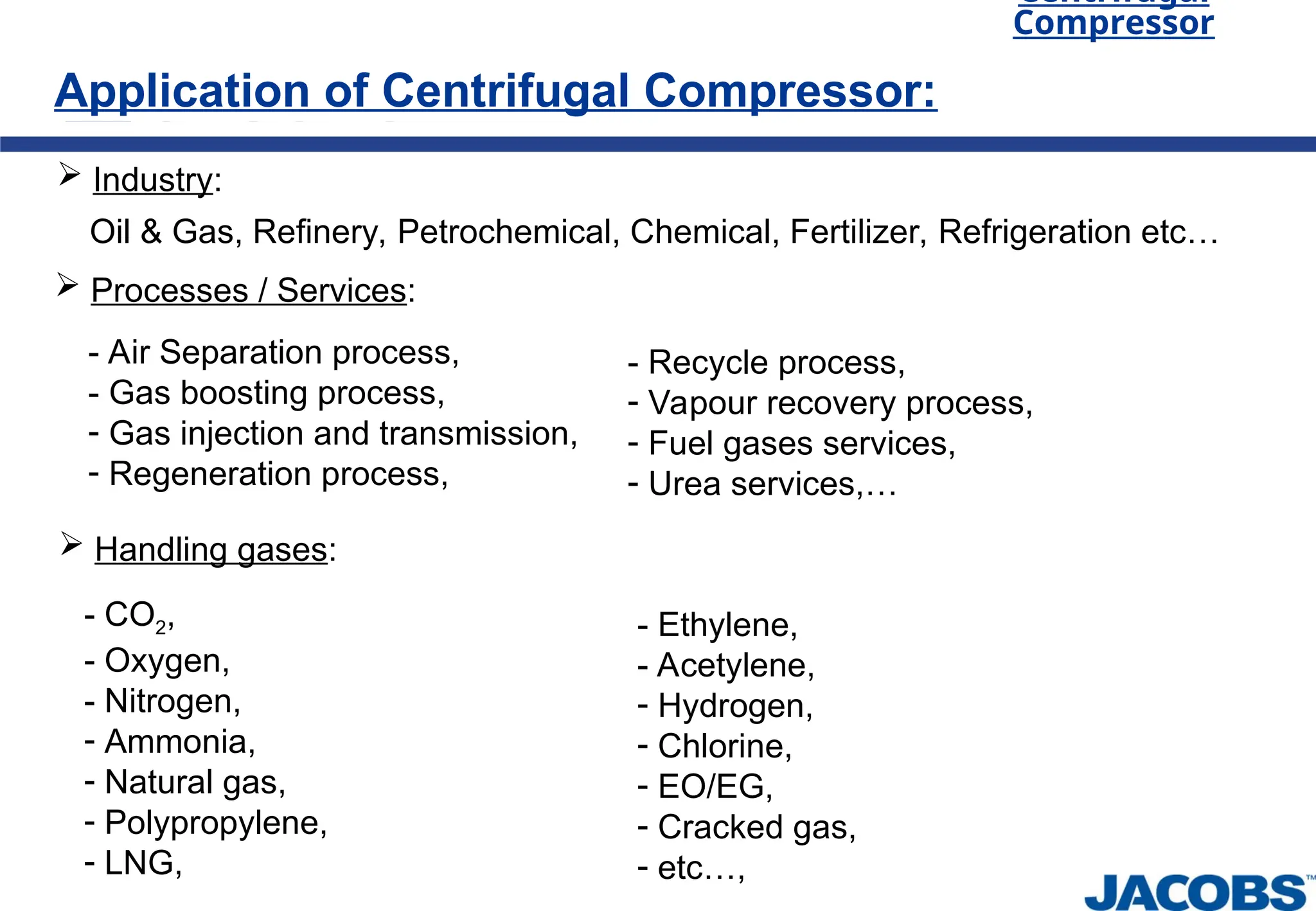
Theory of Compressor
Centrifugal
Compressor
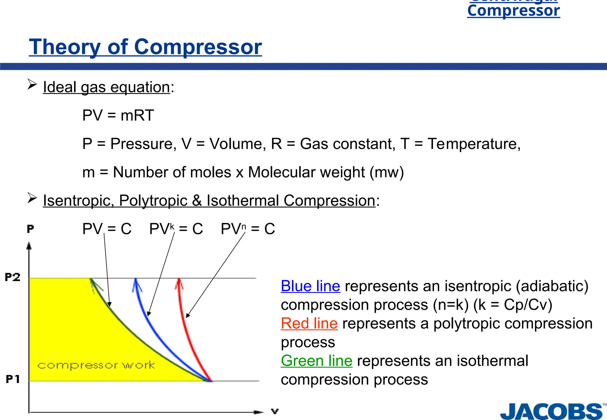
Ideal gas equation:
PV = mRT
P = Pressure, V = Volume, R = Gas constant, T = Temperature,
m = Number of moles x Molecular weight (mw)
Isentropic, Polytropic & Isothermal Compression:
PV = C PVk
= C PVn
= C
Blue line represents an isentropic (adiabatic)
compression process (n=k) (k = Cp/Cv)
Red line represents a polytropic compression
process
Green line represents an isothermal
compression process
7.
Theory of Compressor
Centrifugal
Compressor
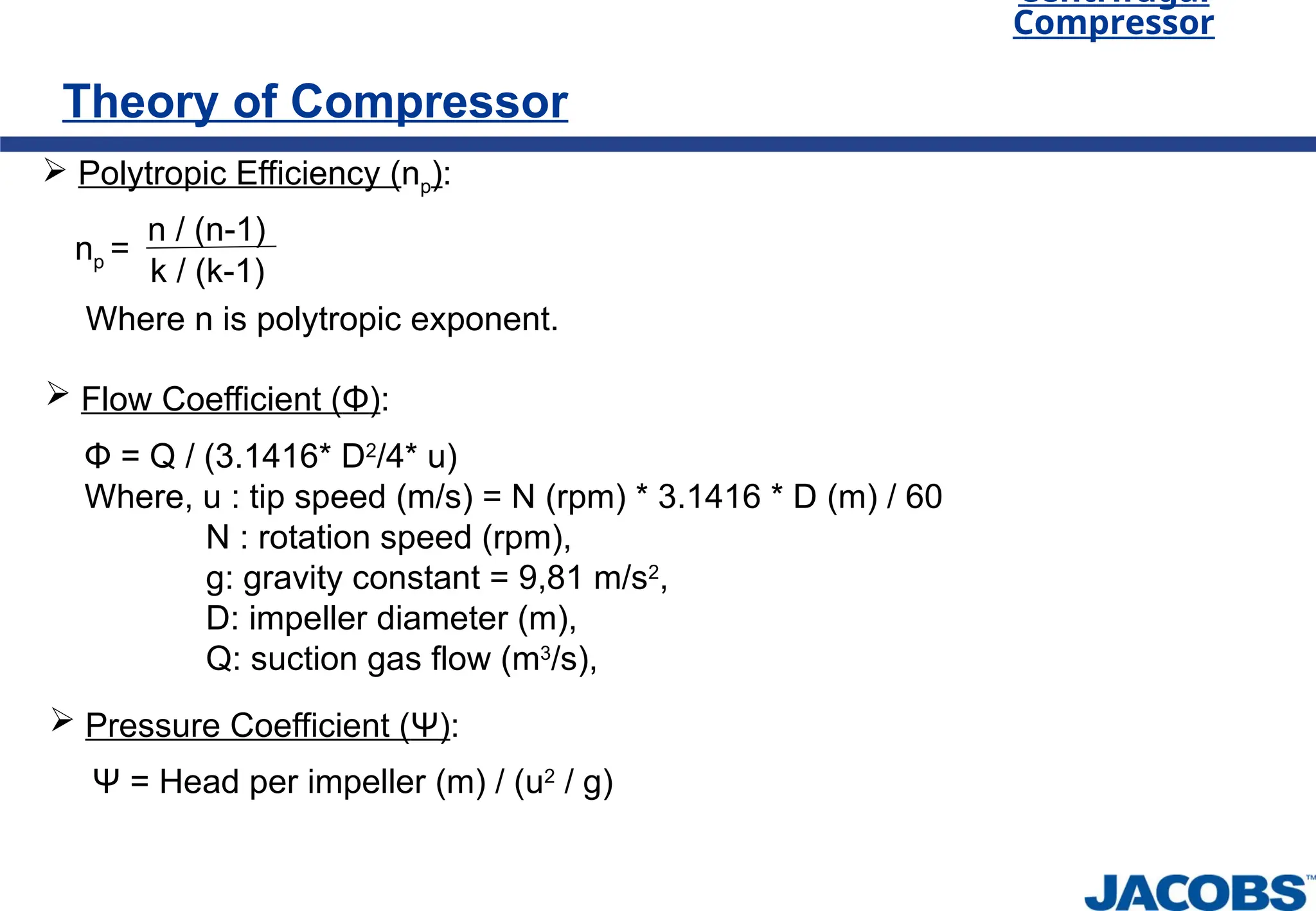
Polytropic Efficiency (np):
np =
n / (n-1)
k / (k-1)
Where n is polytropic exponent.
Flow Coefficient (Φ):
Φ = Q / (3.1416* D2
/4* u)
Where, u : tip speed (m/s) = N (rpm) * 3.1416 * D (m) / 60
N : rotation speed (rpm),
g: gravity constant = 9,81 m/s2
,
D: impeller diameter (m),
Q: suction gas flow (m3
/s),
Ψ = Head per impeller (m) / (u2
/ g)
Pressure Coefficient (Ψ):
Centrifugal
Compressor
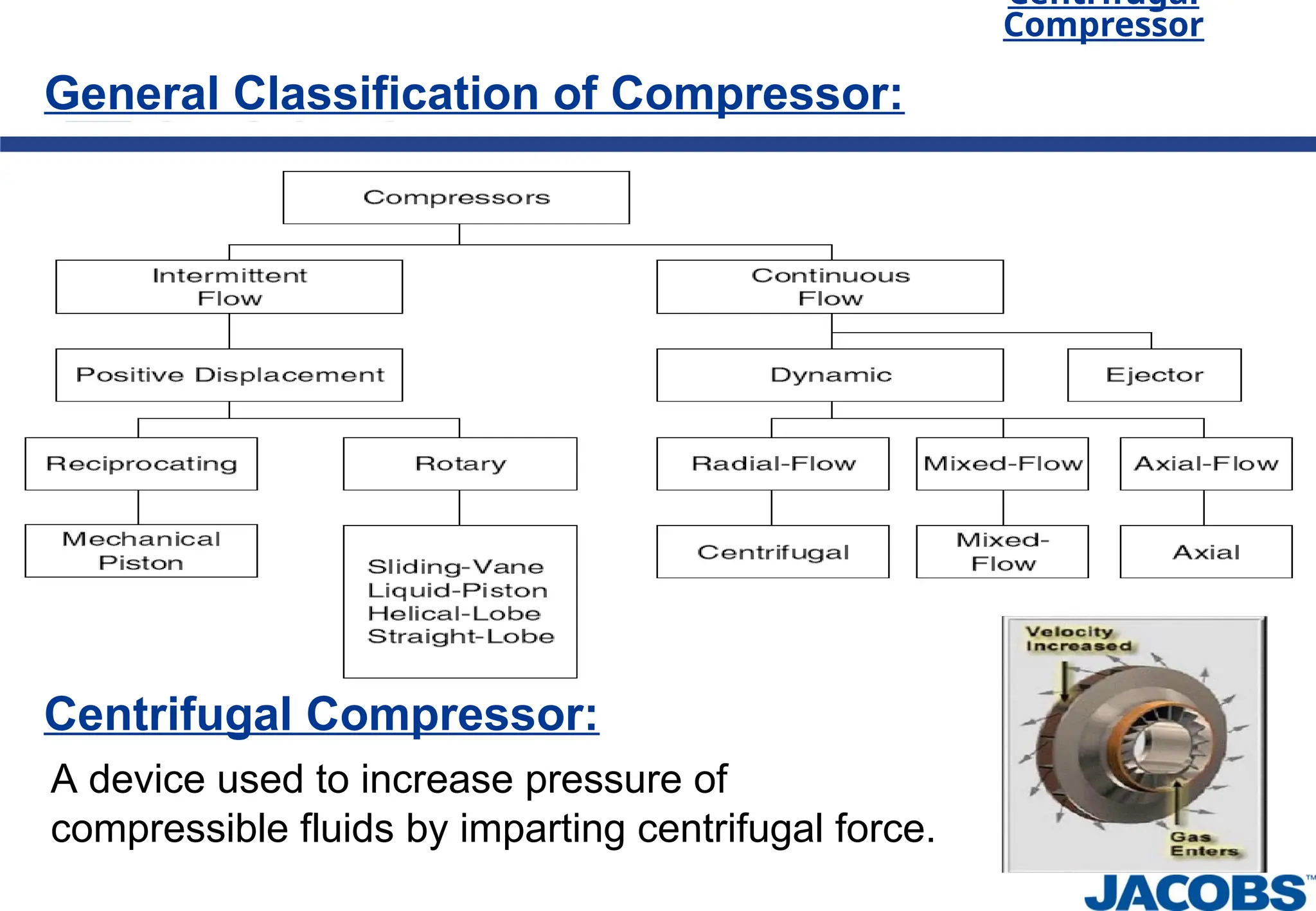
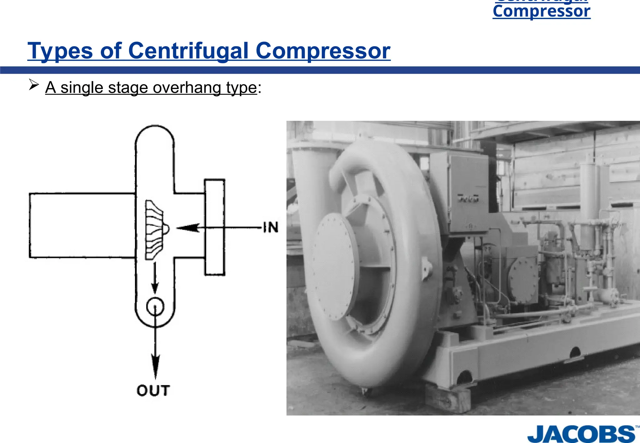
Types of CentrifugalCompressor
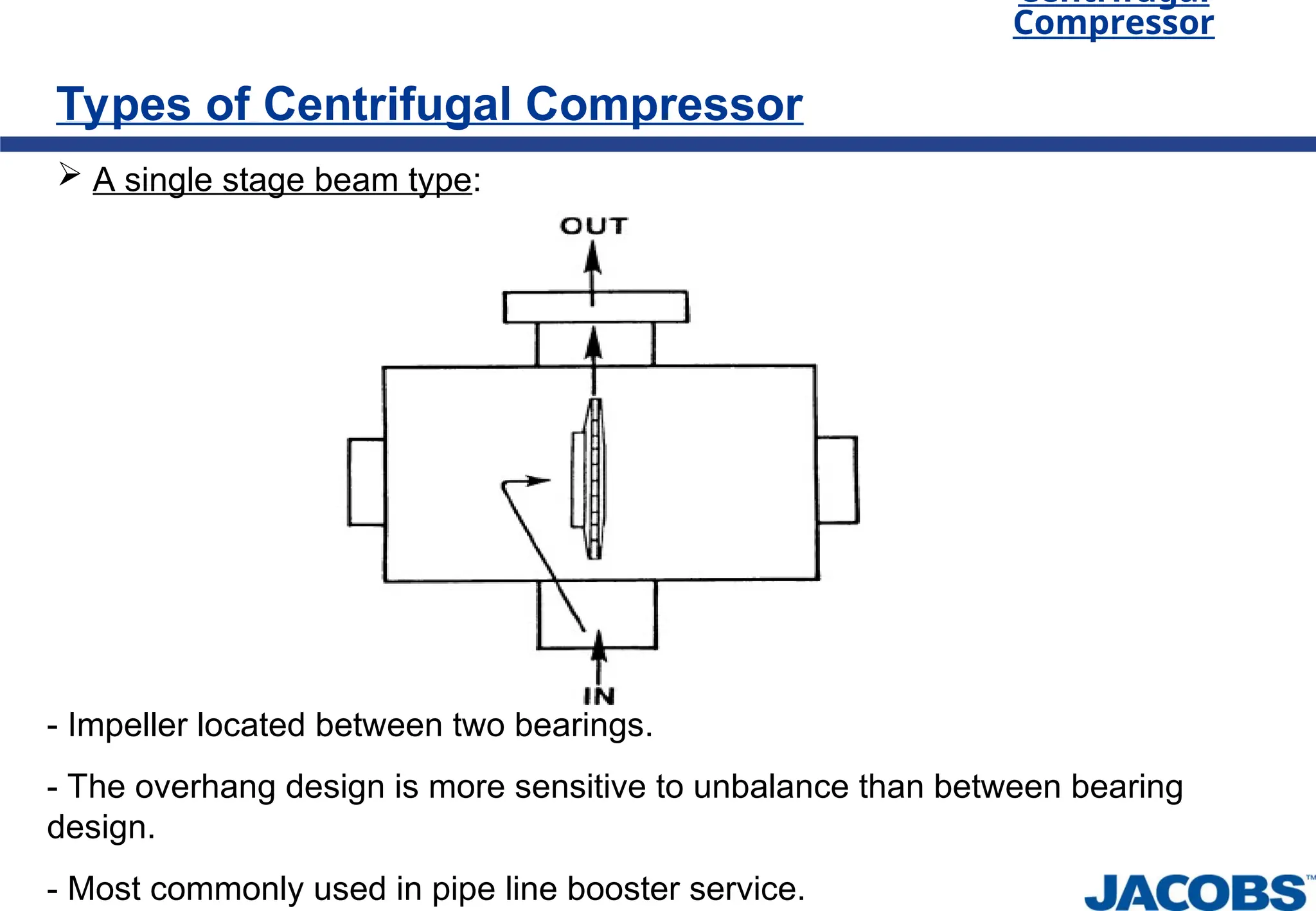
A single stage beam type:
- Impeller located between two bearings.
- The overhang design is more sensitive to unbalance than between bearing
design.
- Most commonly used in pipe line booster service.
10.
Centrifugal
Compressor
Types of CentrifugalCompressor
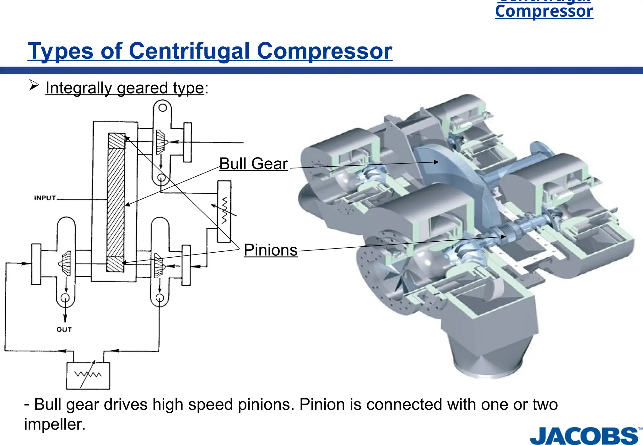
Integrally geared type:
- Bull gear drives high speed pinions. Pinion is connected with one or two
impeller.
Bull Gear
Pinions
11.
Centrifugal
Compressor
Types of CentrifugalCompressor
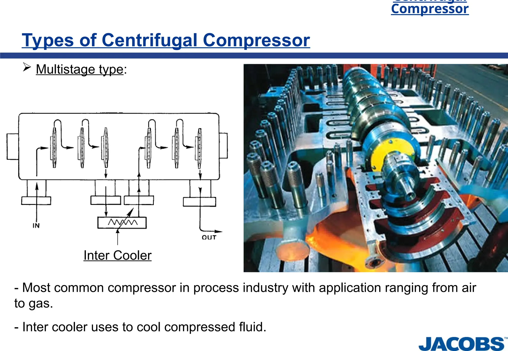
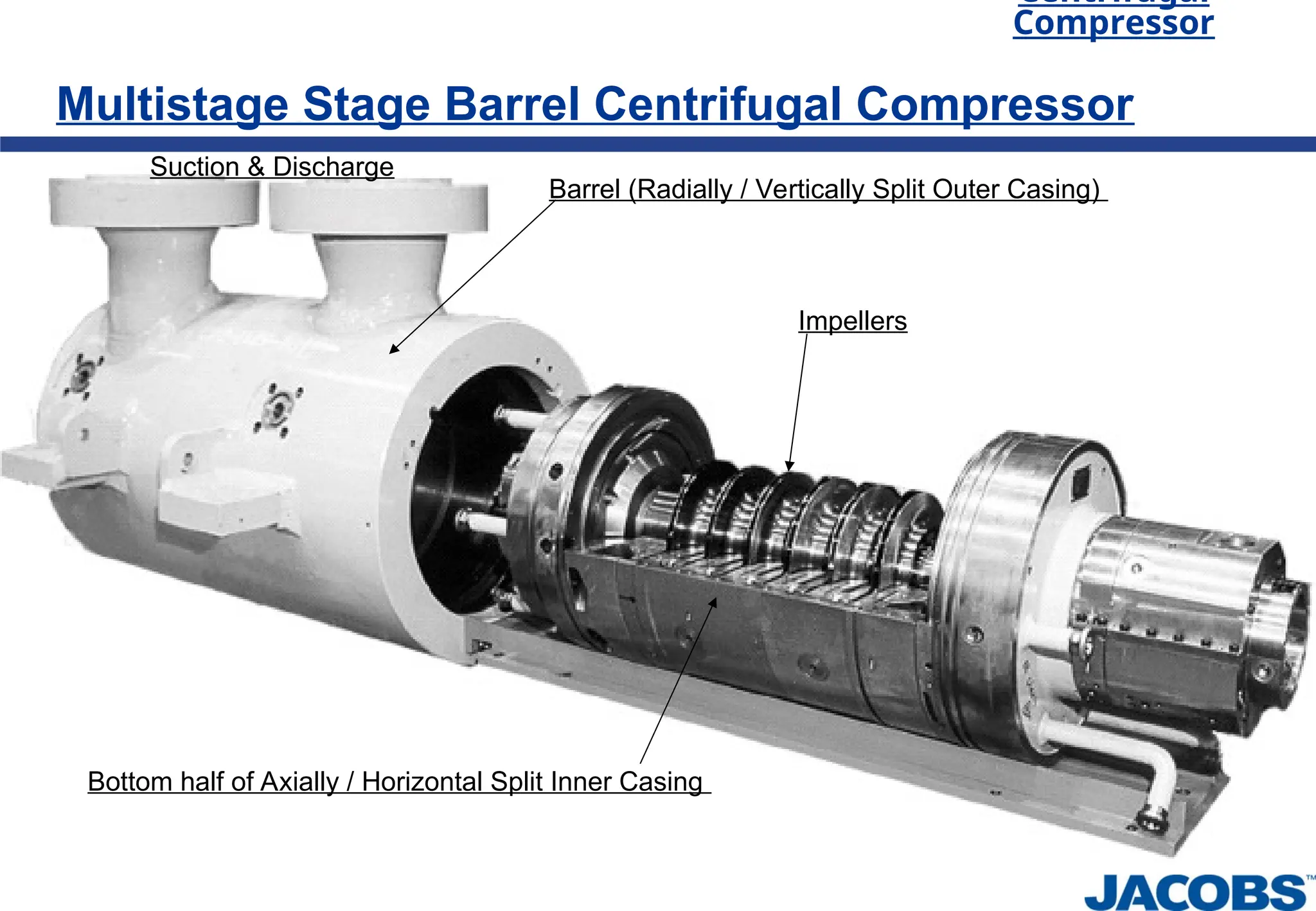
Multistage type:
- Most common compressor in process industry with application ranging from air
to gas.
- Inter cooler uses to cool compressed fluid.
Inter Cooler
12.
Centrifugal
Compressor
Types of CentrifugalCompressor
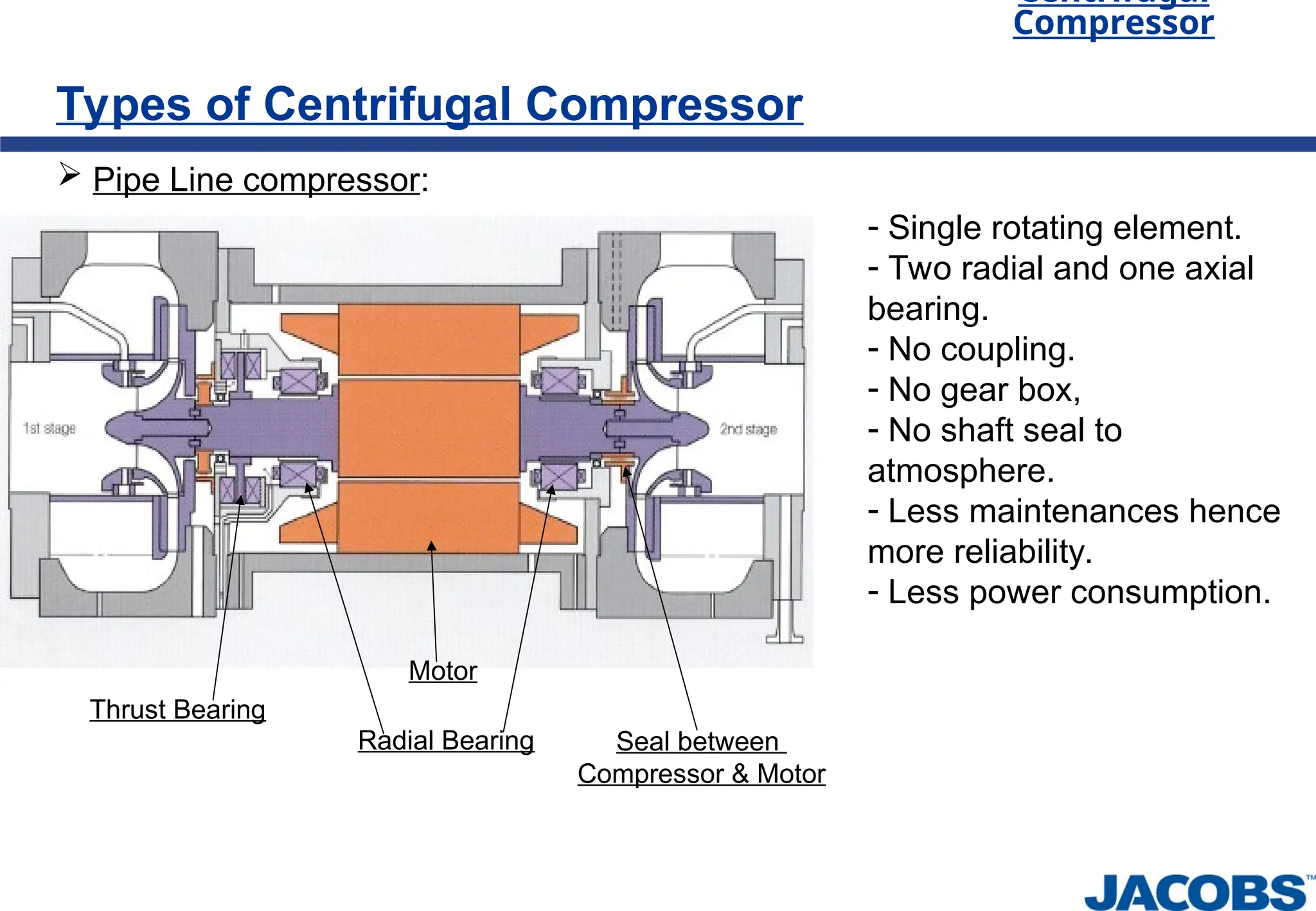
Pipe Line compressor:
Thrust Bearing
Radial Bearing
Motor
- Single rotating element.
- Two radial and one axial
bearing.
- No coupling.
- No gear box,
- No shaft seal to
atmosphere.
- Less maintenances hence
more reliability.
- Less power consumption.
Seal between
Compressor & Motor
Centrifugal
Compressor
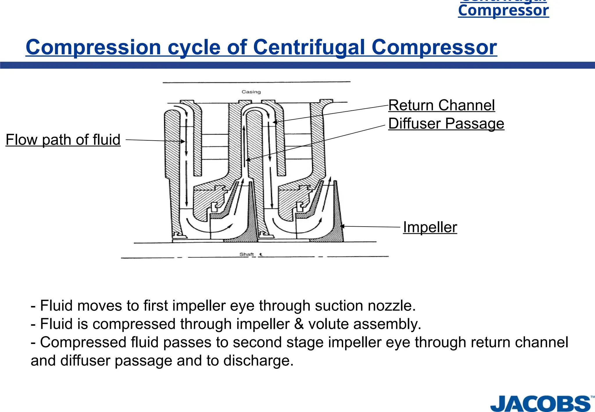
Compression cycle ofCentrifugal Compressor
Impeller
Flow path of fluid
- Fluid moves to first impeller eye through suction nozzle.
- Fluid is compressed through impeller & volute assembly.
- Compressed fluid passes to second stage impeller eye through return channel
and diffuser passage and to discharge.
Return Channel
Diffuser Passage
17.
Centrifugal
Compressor
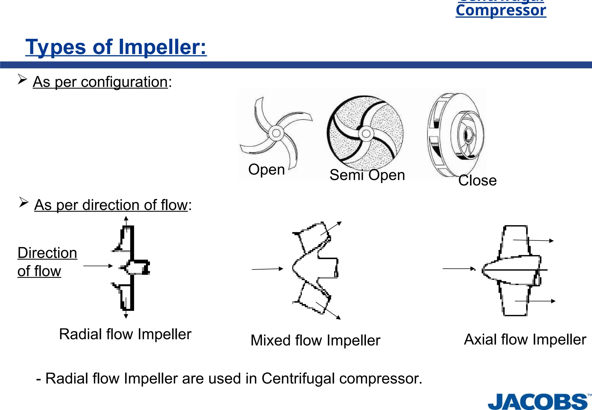
Types of Impeller:
As per configuration:
Open Semi Open Close
As per direction of flow:
Radial flow Impeller Axial flow Impeller
Mixed flow Impeller
Direction
of flow
- Radial flow Impeller are used in Centrifugal compressor.
18.
Centrifugal
Compressor
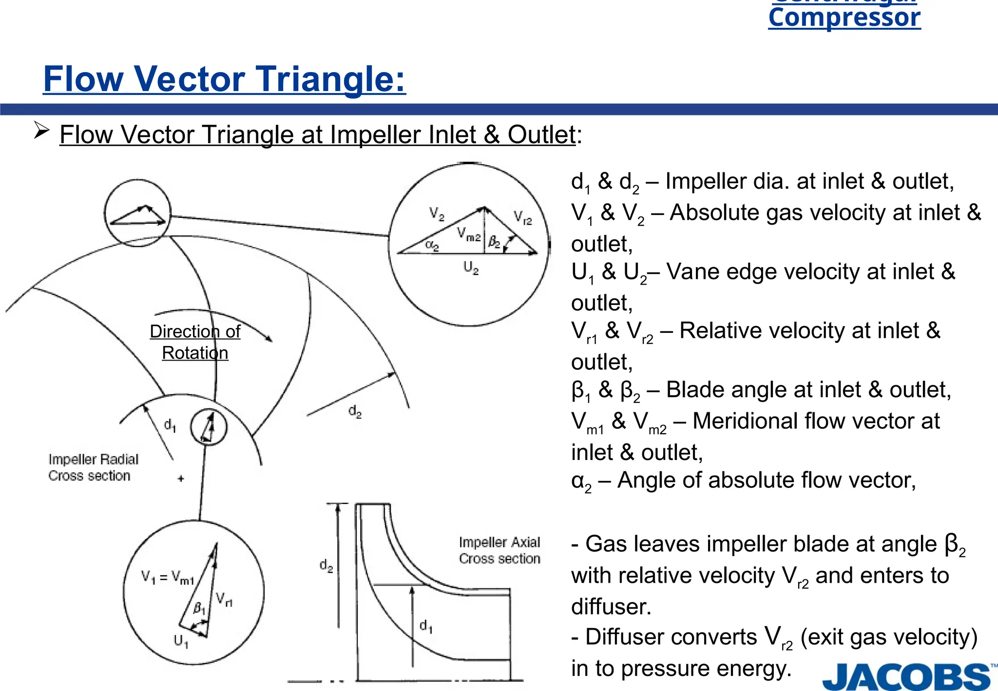
Flow Vector Triangle:
Flow Vector Triangle at Impeller Inlet & Outlet:
Direction of
Rotation
d1 & d2 – Impeller dia. at inlet & outlet,
V1 & V2 – Absolute gas velocity at inlet &
outlet,
U1 & U2– Vane edge velocity at inlet &
outlet,
Vr1 & Vr2 – Relative velocity at inlet &
outlet,
β1 & β2 – Blade angle at inlet & outlet,
Vm1 & Vm2 – Meridional flow vector at
inlet & outlet,
α2 – Angle of absolute flow vector,
- Gas leaves impeller blade at angle β2
with relative velocity Vr2 and enters to
diffuser.
- Diffuser converts Vr2 (exit gas velocity)
in to pressure energy.
Centrifugal
Compressor
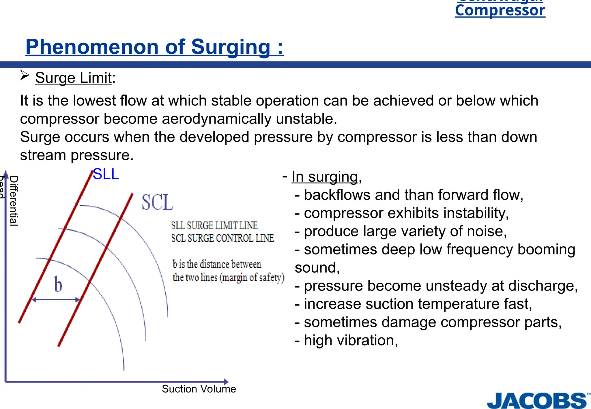
Phenomenon of Surging:
Surge Limit:
It is the lowest flow at which stable operation can be achieved or below which
compressor become aerodynamically unstable.
Surge occurs when the developed pressure by compressor is less than down
stream pressure.
- In surging,
- backflows and than forward flow,
- compressor exhibits instability,
- produce large variety of noise,
- sometimes deep low frequency booming
sound,
- pressure become unsteady at discharge,
- increase suction temperature fast,
- sometimes damage compressor parts,
- high vibration,
Differential
Suction Volume
SLL
21.
Centrifugal
Compressor
Phenomenon of Surging:
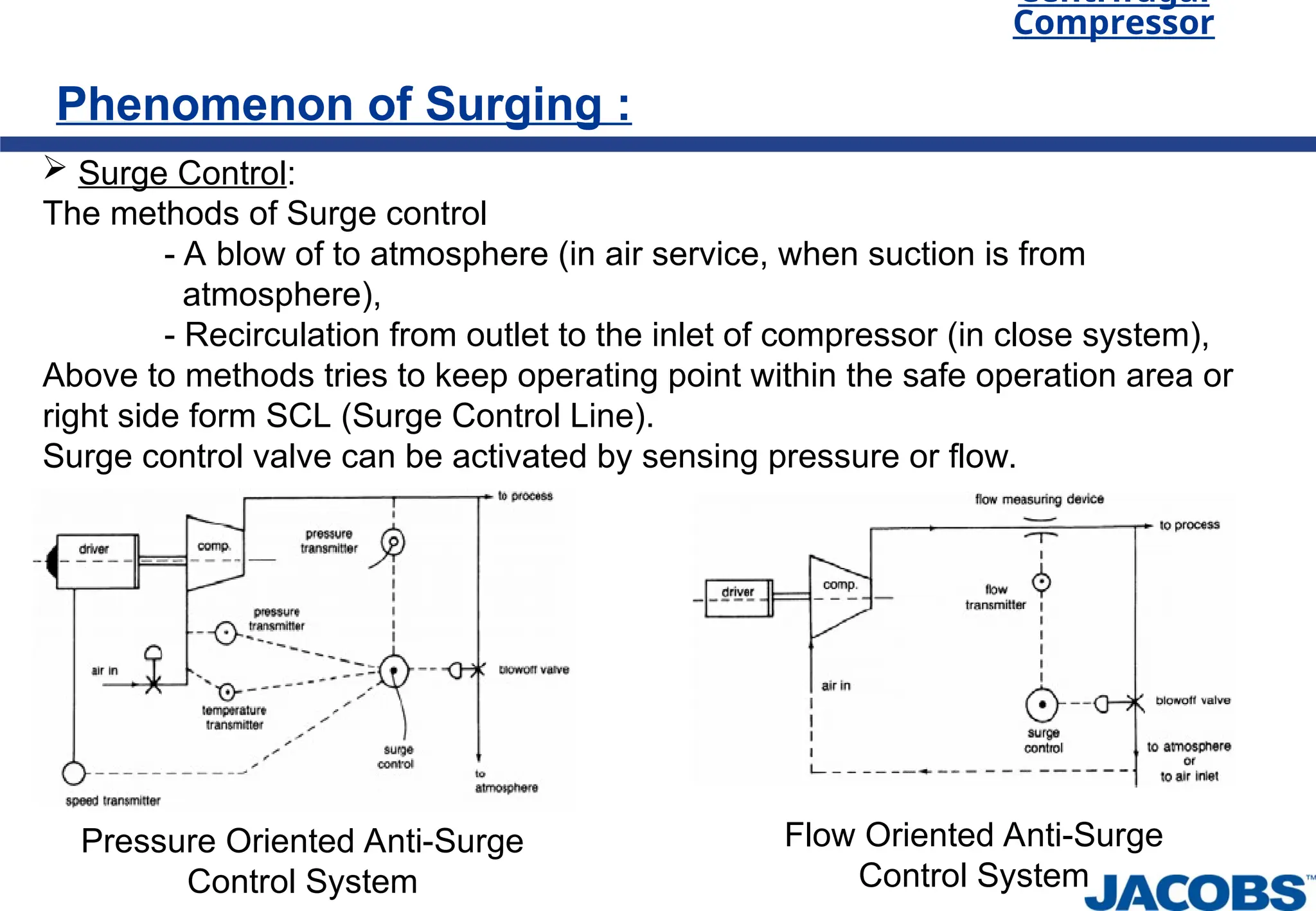
Surge Control:
The methods of Surge control
- A blow of to atmosphere (in air service, when suction is from
atmosphere),
- Recirculation from outlet to the inlet of compressor (in close system),
Above to methods tries to keep operating point within the safe operation area or
right side form SCL (Surge Control Line).
Surge control valve can be activated by sensing pressure or flow.
Pressure Oriented Anti-Surge
Control System
Flow Oriented Anti-Surge
Control System
22.
Centrifugal
Compressor
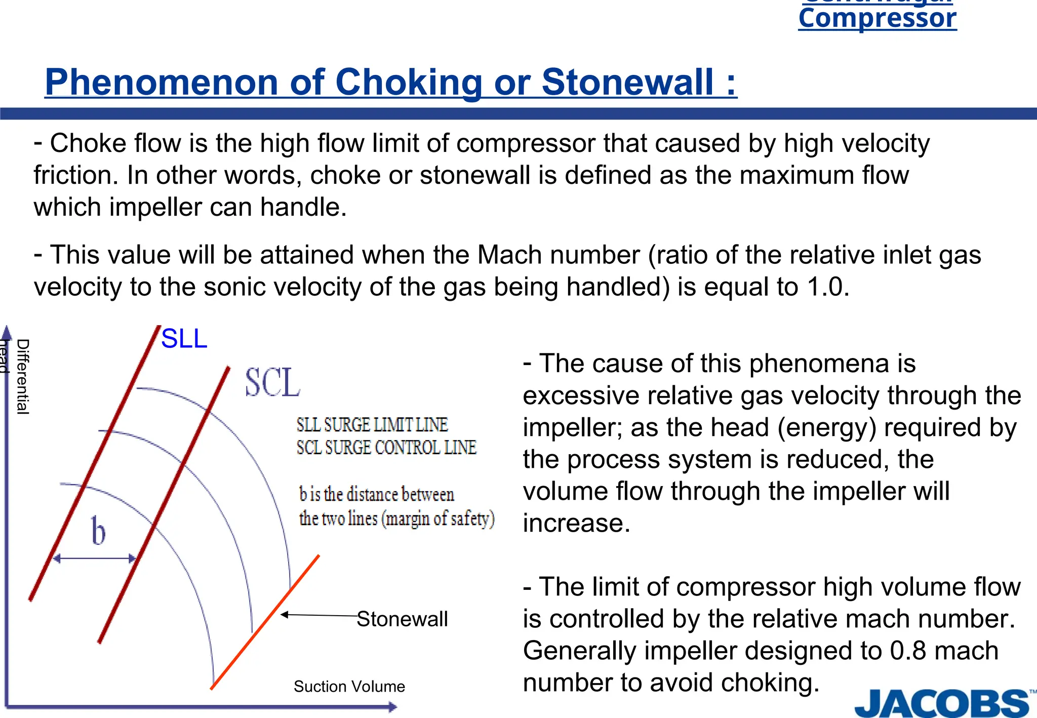
Phenomenon of Chokingor Stonewall :
- Choke flow is the high flow limit of compressor that caused by high velocity
friction. In other words, choke or stonewall is defined as the maximum flow
which impeller can handle.
- This value will be attained when the Mach number (ratio of the relative inlet gas
velocity to the sonic velocity of the gas being handled) is equal to 1.0.
Stonewall
Differential
Suction Volume
- The cause of this phenomena is
excessive relative gas velocity through the
impeller; as the head (energy) required by
the process system is reduced, the
volume flow through the impeller will
increase.
- The limit of compressor high volume flow
is controlled by the relative mach number.
Generally impeller designed to 0.8 mach
number to avoid choking.
SLL
23.
Centrifugal
Compressor
Capacity Control:
ByVariable Speed Control:
- With changing speed of driver.
By Suction Throttling:
- With throttling of suction valve.
- Reduce inlet volume of gas.
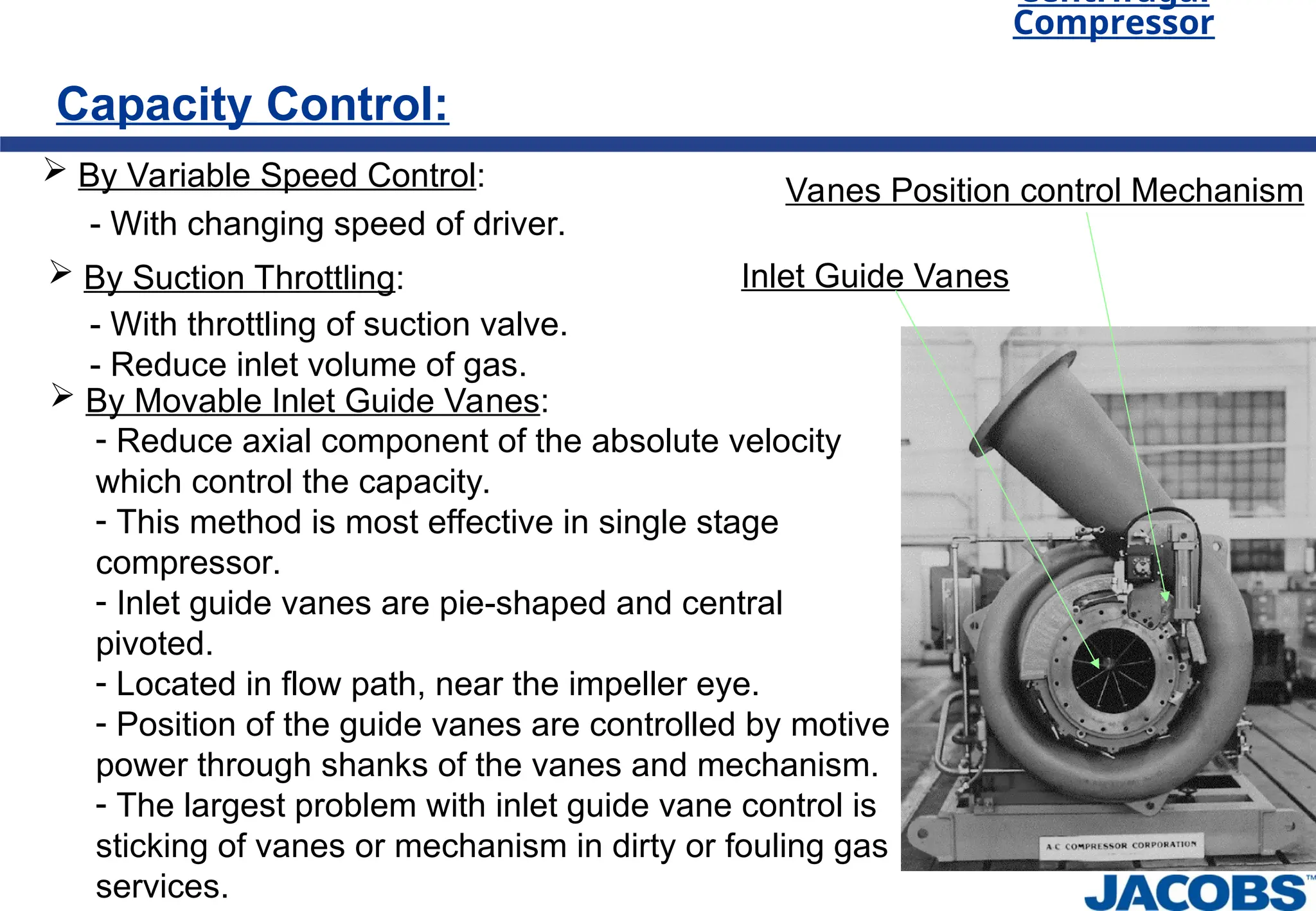
By Movable Inlet Guide Vanes:
- Reduce axial component of the absolute velocity
which control the capacity.
- This method is most effective in single stage
compressor.
- Inlet guide vanes are pie-shaped and central
pivoted.
- Located in flow path, near the impeller eye.
- Position of the guide vanes are controlled by motive
power through shanks of the vanes and mechanism.
- The largest problem with inlet guide vane control is
sticking of vanes or mechanism in dirty or fouling gas
services.
Inlet Guide Vanes
Vanes Position control Mechanism
24.
Centrifugal
Compressor
Auxiliary of CompressorPackage:
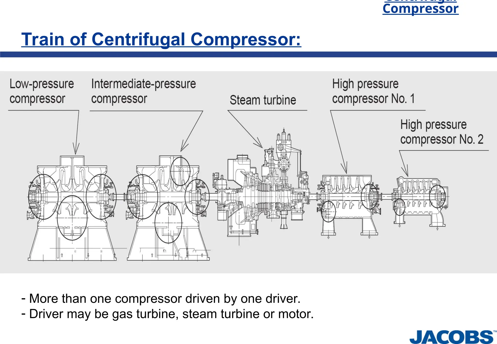
Driver:
- Compressor driver may be electrical motor or steam turbine or gas turbine or
expander.
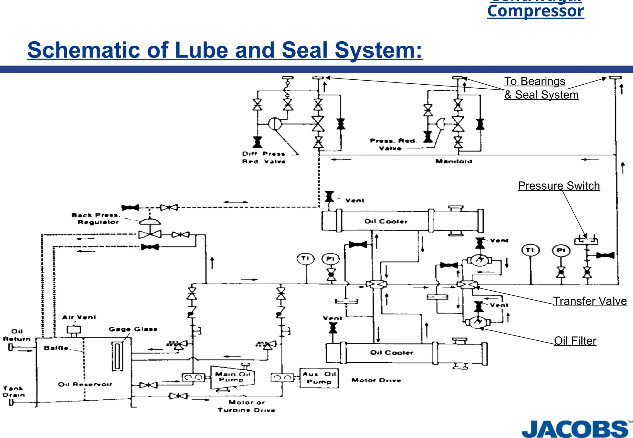
Lube oil system:
- Normally contains oil reservoir, oil pumps, oil filters, oil cooler and related piping
& instrumentations.
- Lubricate bearings of compressor & driver and gear box.
Inter cooler and after cooler:
- Cool gas before enter next stage of compression or down stream.
Vibration and Temperature monitoring system:
- Vibration probe and RTD are used.
Seal system:
- Prevent leakage of gas from compressor.
Coupling:
Gear unit:
Centrifugal
Compressor
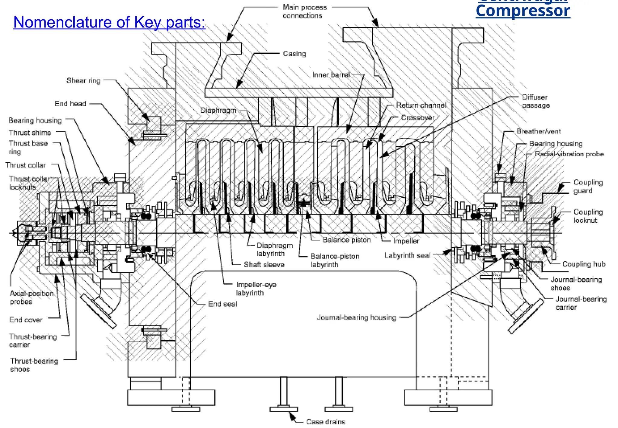
Compressor Seal System:
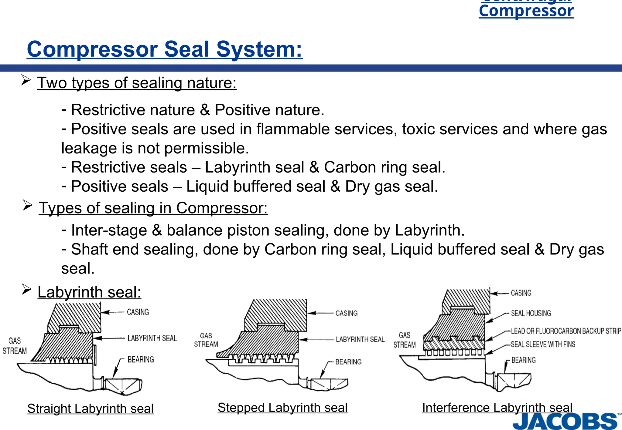
Two types of sealing nature:
- Restrictive nature & Positive nature.
- Positive seals are used in flammable services, toxic services and where gas
leakage is not permissible.
- Restrictive seals – Labyrinth seal & Carbon ring seal.
- Positive seals – Liquid buffered seal & Dry gas seal.
Types of sealing in Compressor:
- Inter-stage & balance piston sealing, done by Labyrinth.
- Shaft end sealing, done by Carbon ring seal, Liquid buffered seal & Dry gas
seal.
Labyrinth seal:
Straight Labyrinth seal Interference Labyrinth seal
Stepped Labyrinth seal
27.
Centrifugal
Compressor
Compressor Seal System:
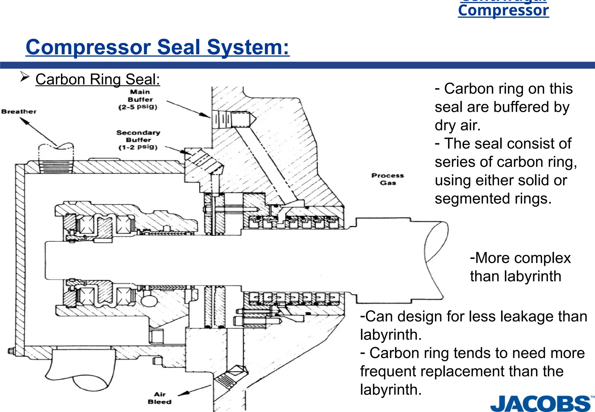
Carbon Ring Seal:
- Carbon ring on this
seal are buffered by
dry air.
- The seal consist of
series of carbon ring,
using either solid or
segmented rings.
-Can design for less leakage than
labyrinth.
- Carbon ring tends to need more
frequent replacement than the
labyrinth.
-More complex
than labyrinth
28.
Centrifugal
Compressor
Compressor Seal System:
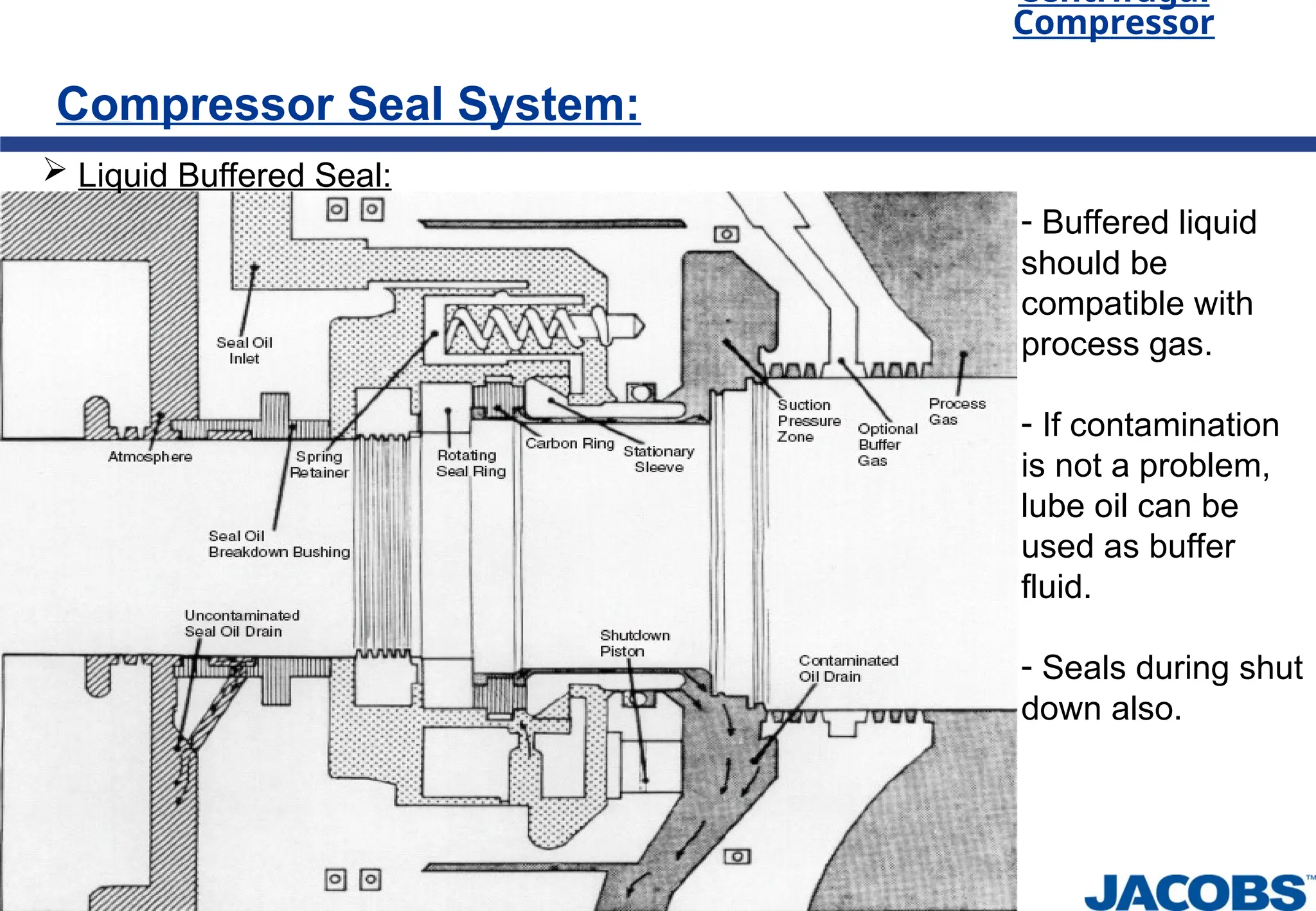
Liquid Buffered Seal:
- Buffered liquid
should be
compatible with
process gas.
- If contamination
is not a problem,
lube oil can be
used as buffer
fluid.
- Seals during shut
down also.
29.
Centrifugal
Compressor
Compressor Seal System:
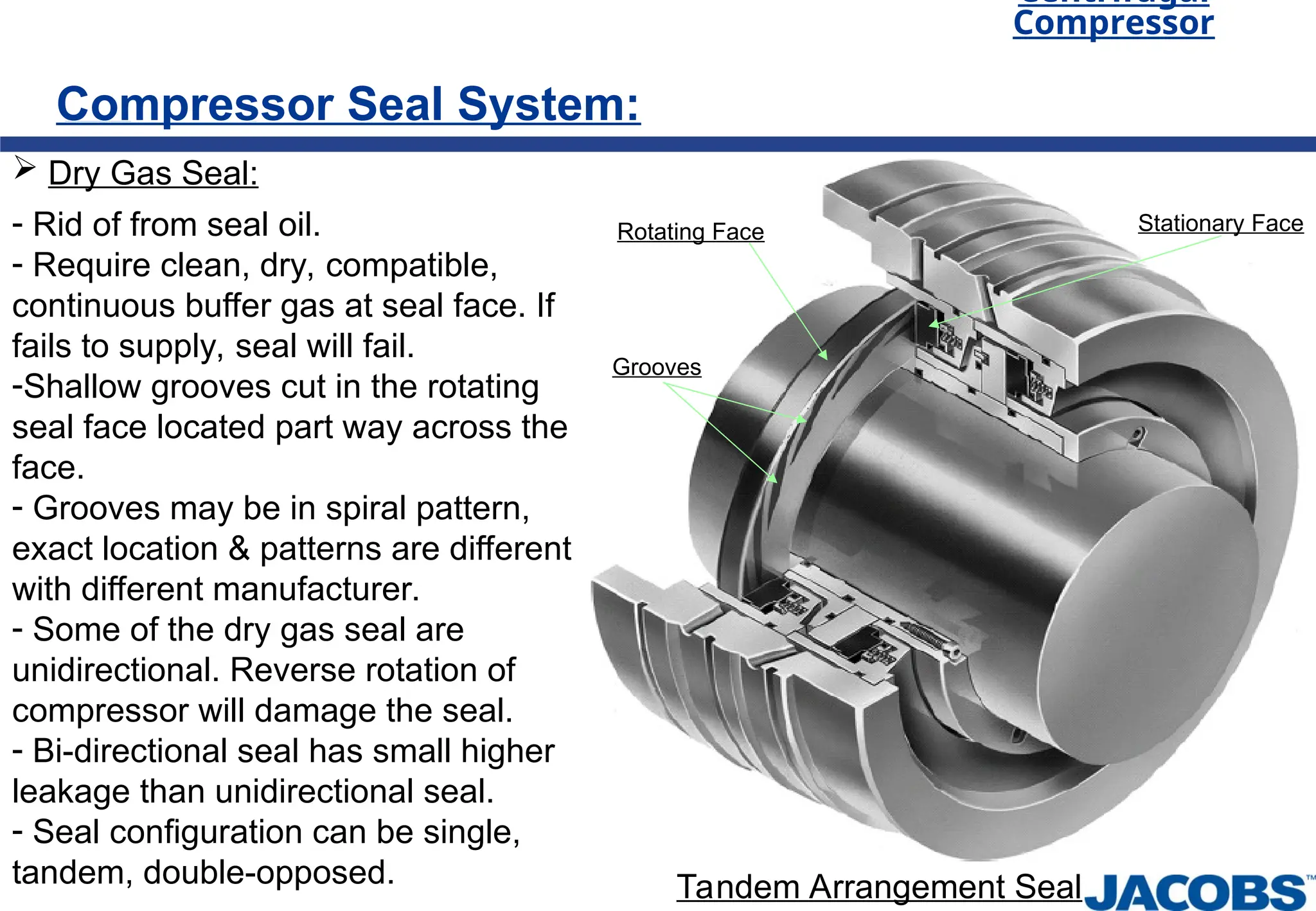
Dry Gas Seal:
- Rid of from seal oil.
- Require clean, dry, compatible,
continuous buffer gas at seal face. If
fails to supply, seal will fail.
-Shallow grooves cut in the rotating
seal face located part way across the
face.
- Grooves may be in spiral pattern,
exact location & patterns are different
with different manufacturer.
- Some of the dry gas seal are
unidirectional. Reverse rotation of
compressor will damage the seal.
- Bi-directional seal has small higher
leakage than unidirectional seal.
- Seal configuration can be single,
tandem, double-opposed.
Rotating Face Stationary Face
Grooves
Tandem Arrangement Seal
30.
Centrifugal
Compressor
Compressor Rotor Analysis:
RotorBalancing:
- Compressor rotor is balanced to Gr. 1 as per ISO 1940/1.
- In Gr. 1, Maximum permissible residual unbalance is ~1.3 g mm / kg of rotor
weight at 10000 rpm speed. Value of maximum permissible residual unbalance
decreases with increasing speed.
Stability Analysis:
- The determination of the natural frequencies and the corresponding logarithmic
decrements of the rotor/support system.
Lateral Analysis:
- Critical speeds and their associated Amplitude Factors shall be determined by
means of a damped unbalanced rotor response analysis.
Torsional Analysis:
- Torsional vibration analysis of the complete coupled train is carried out and shall
be responsible for directing any modifications necessary to meet the requirements.
-Torsional analysis is generally performed on motor-driven units and units
including gears, units comprising three or more coupled machines (excluding any
gears)
31.
Centrifugal
Compressor
Selection of compressor:
Selectionof compressor are based on following points,
- Suitability of service,
- Capacity and differential pressure,
- Gas composition,
- Molecular weight of gas,
- Operating cost,
- Space available in layout with maintenance space.
- Market availability for specified service and operating point,