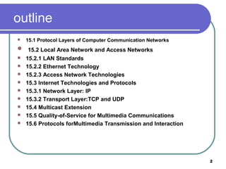
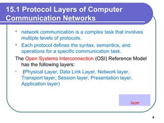
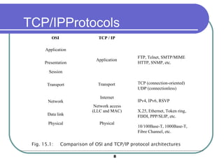
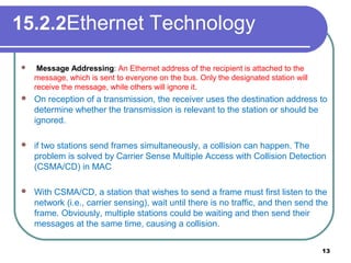
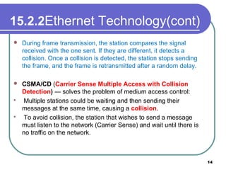
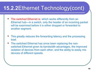
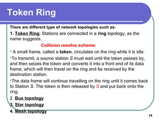
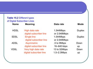
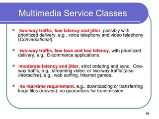
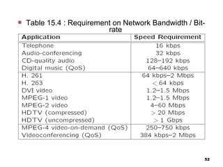
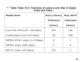
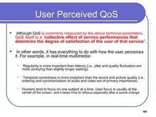
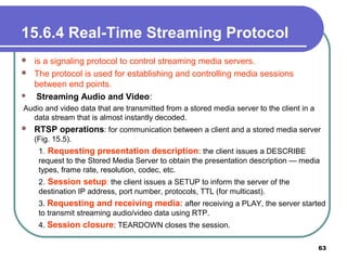
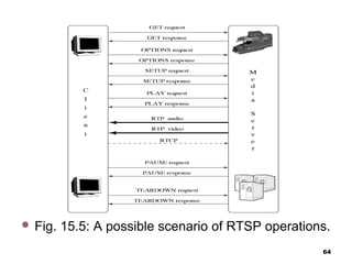
Network Services and protocols
for Multimedia Communications
1
outline
 15.1 Protocol Layers of Computer Communication Networks
 15.2 Local Area Network and Access Networks
 15.2.1 LAN Standards
 15.2.2 Ethernet Technology
 15.2.3 Access Network Technologies
 15.3 Internet Technologies and Protocols
 15.3.1 Network Layer: IP
 15.3.2 Transport Layer:TCP and UDP
 15.4 Multicast Extension
 15.5 Quality-of-Service for Multimedia Communications
 15.6 Protocols forMultimedia Transmission and Interaction
2
Basics of Computer and Multimedia
Networks
 Computer networks are essential to modern
computing.
 Multimedia networks share all major issues and
technologies of computer networks.
 The ever-growing needs for various multimedia
communications have made networks one of the most
active areas for research and development.
 Various high-speed networks are becoming a central
part of most contemporary multimedia systems.
3
15.1 Protocol Layers of Computer
Communication Networks
 network communication is a complex task that involves
multiple levels of protocols.
 Each protocol defines the syntax, semantics, and
operations for a specific communication task.
The Open Systems Interconnection (OSI) Reference Model
has the following layers:
• (Physical Layer, Data Link Layer, Network layer,
Transport layer, Session layer, Presentation layer,
Application layer)
4
layer
15.1 Protocol Layers of Computer
Communication Networks
• Multimedia systems are generally
implemented in the last three layers.
• The OSI model however has never been fully
implemented; instead, the competing and
more practical TCP/IP protocol suite has
become dominating, which is also the core
protocols for the transport and network layers
of today’s Internet.
5
OSI Network Layers
 OSI Reference Model has the following network layers:
1. Physical Layer: Defines electrical and mechanical properties of
the physical interface, and specifies the functions and procedural
sequences performed by circuits of the physical interface.
2. Data Link Layer: Specifies the ways to establish, maintain and
terminate a link, e.g., transmission and synchronization of data
frames, error detection and correction, and access protocol to the
Physical layer.
3. Network Layer: Defines the routing of data from one end to
the other across the network. Provides services such as
addressing, internetworking, error handling, congestion control,
and sequencing of packets.
6
OSI Network Layers (Cont’d)
4. Transport Layer: Provides end-to-end communication between end
systems that support end-user applications or services.Supports either
connection-oriented or connectionless protocols. Provides error recovery and
flow control.
5. Session Layer: Coordinates interaction between user applications on
different hosts, manages sessions (connections), e.g., completion of long file
transfers.
6. Presentation Layer: Deals with the syntax of transmitted data, e.g.,
conversion of different data formats and codes due to different conventions,
compression or encryption.
7. Application Layer: Supports various application programs
and protocols, e.g., FTP, Telnet, HTTP, SNMP, SMTP/MIME,
etc.
7
TCP/IPProtocols
Application
Transport
Internet
Network access
(LLC and MAC)
Physical
FTP, Telnet, SMTP/MIME
HTTP, SNMP, etc.
TCP (connection-oriented)
UDP (connectionless)
IPv4, IPv6, RSVP
X.25, Ethernet, Token ring,
FDDI, PPP/SLIP, etc.
10/100Base-T, 1000Base-T,
Fibre Channel, etc.
TCP / IP
Application
Presentation
Session
Transport
Network
Data link
Physical
OSI
Fig. 15.1: Comparison of OSI and TCP/IP protocol architectures
8
15.2 Local Area Network and Access
Network
• For home or office users, the networks of direct use is
generally a LAN, which is restricted to a small
geographical area, usually for a relatively small number
of stations.
• Access Network is: The physical links that connect an
end system inside a LAN toward the external Internet.
9
• A firewall is a network security system designed to prevent unauthorized
access to or from a private network.
• Firewalls can be implemented in both hardware and software, or a
combination of both.
• Network firewalls are frequently used to prevent unauthorized Internet users
from accessing private networks connected to the Internet, especially
intranets.
• All messages entering or leaving the intranet pass through the firewall,
which examines each message and blocks those that do not meet the
specified security criteria.
10
15.2.1 LAN Standards
 In IEEE 802 Reference Model for LANs, the functionality of the
Data Link layer is enhanced, and it has been divided into two
sublayers:
 Medium Access Control (MAC) layer:
 (a) Assemble or disassemble frames upon transmission or
reception.
 (b) perform addressing and error correction.
 (c) Access control to shared physical medium.
 Logical Link Control (LLC) layer:
 (a) Flow and error control.
 (b) MAC-layer addressing.

(c) Interface to higher layers. LLC is above MAC in the hierarchy.
11
15.2.2 Ethernet Technology
 Ethernet: Ethernet is a LAN technology initially developed at Xerox PARC
in 1970, it is a packet-switched bus network, the most popular LAN to date.
 Each Ethernet station is given a 48-bitMAC address. The MAC addresses
are used to specify both the destination and the source of each data
packet, referred to as a frame.
 Ethernet frame structure, which begins with a preamble and a start of frame
delimiter, followed by an Ethernet header featuring source and destination
MAC addresses.
 The middle section of the frame consists of the payload data including any
headers for other protocols (e.g., IP) carried in the frame. The frame ends
with a 32-bit cyclic redundancy check (CRC, see Chap. 17), which is used
to detect data corruption in transit.
15.2.2Ethernet Technology
 Message Addressing: An Ethernet address of the recipient is attached to the
message, which is sent to everyone on the bus. Only the designated station will
receive the message, while others will ignore it.
 On reception of a transmission, the receiver uses the destination address to
determine whether the transmission is relevant to the station or should be
ignored.
 if two stations send frames simultaneously, a collision can happen. The
problem is solved by Carrier Sense Multiple Access with Collision Detection
(CSMA/CD) in MAC
 With CSMA/CD, a station that wishes to send a frame must first listen to the
network (i.e., carrier sensing), wait until there is no traffic, and then send the
frame. Obviously, multiple stations could be waiting and then send their
messages at the same time, causing a collision.
13
15.2.2Ethernet Technology(cont)
 During frame transmission, the station compares the signal
received with the one sent. If they are different, it detects a
collision. Once a collision is detected, the station stops sending
the frame, and the frame is retransmitted after a random delay.
 CSMA/CD (Carrier Sense Multiple Access with Collision
Detection) — solves the problem of medium access control:
 Multiple stations could be waiting and then sending their
messages at the same time, causing a collision.
 To avoid collision, the station that wishes to send a message
must listen to the network (Carrier Sense) and wait until there is
no traffic on the network.
14
15.2.2Ethernet Technology(cont)
 The switched Ethernet is: which works differently from an
Ethernet hub—in a switch, only the header of an incoming packet
will be examined before it is either dropped or forwarded to
another segment.
 This greatly reduces the forwarding latency and the processing
load.
 The switched Ethernet has since been replacing the non-
switched Ethernet given its bandwidth advantages, the improved
isolation of devices from each other, and the ability to easily mix
devices of different speeds.
15
Token Ring
There are different type of network topologies such as:
1. Token Ring: Stations are connected in a ring topology, as the
name suggests.
Collision resolve scheme:
 A small frame, called a token, circulates on the ring while it is idle.
To transmit, a source station S must wait until the token passes by,
and then seizes the token and converts it into a front end of its data
frame, which will then travel on the ring and be received by the
destination station.
The data frame will continue travelling on the ring until it comes back
to Station S. The token is then released by S and put back onto the
ring.
2. Bus topology
3. Star topology
4. Mesh topology
16
FDDI (Fiber Distributed Data Interface)
• A successor of the original Token Ring. Its Medium Access Control
(MAC) is very similar to the MAC for Token Rings.
• Has a dual ring topology with its primary ring for data transmission
and secondary ring for fault tolerance.
• Once a station captures a token, the station is granted a time period,
and can send as many data frames as it can within the time period.
• The token will be released as soon as the frames are transmitted
(early token release).
• Primarily used in LAN or MAN backbones, and supports both
synchronous and asynchronous modes.
17
15.2.3 Access Network Technologies
• An access network connects end users to the core network. An
access network bridges the LAN in a home or office to the external
Internet.,
• An existing network that is already in the home is often used, in
particular, the telephone or cable TV networks. Direct fiber optics
connections have been popular nowadays for new buildings.
18
15.2.3 Access Network Technologies(cont)
(Dial-Up and Integrated Services Digital
Network)
the Public Switched Telephone Network (PSTN) is widely
available in residential homes and offices.
•the traditional telephone lines carry analog voice signal
only.
•To transmit digital data, a modem (modulator
demodulator) is needed between the computer and the
telephone jack to modulate an analog carrier signal to
encode digital information, and also demodulate a carrier
signal to decode the transmitted information.
(Dial-Up and Integrated Services Digital Network)(cont)
• Dial-up requires time to establish a telephone
connection (up to several seconds, depending on the
location) and perform configuration for protocol
synchronization before data transfers can take place
• The low speed and relatively high delay make dial-up
generally unsuitable for multimedia applications.
• To overcome these limits, in the 1980s, the
International Telecommunication Union (ITU) started
to develop the Integrated Service Digital Network
(ISDN) to transmit digital data, voice, and sometimes
video (e.g., in videoconferencing) can be transmitted
20
15.2.3Access Network Technologies(cont)
(Digital Subscriber Line)
DSL is again makes use of existing telephone’s twisted-pair wires to
transmit .
Unlike traditional dial-up modems, which modulate bits into signals in
the 300–3400Hz baseband (voice service)
 DSL modems modulate frequencies from 4000 to 1MHz (and as high
as 4MHz)
using Quadrature Amplitude Modulation (QAM).
 DSL employs highly complex digital signal processing algorithms to
overcome the inherent limitations of the existing twisted pair wires.
 Till the late modulated digital data signal
21
(Digital Subscriber Line) (cont)
One important technology is Discrete Multi-Tone (DMT), which, for better
transmission in potentially noisy channels (either downstream or upstream),
sends test signals to all subchannels first. It then calculates the signal-to-
noise ratio (SNR),to dynamically determine the amount of data to be sent in
each subchannel.
DSL uses FDM (Frequency Division Multiplexing) to multiplex three
channels:
• The high-speed (1.5–9Mbps) downstream channel at the high end of the
spectrum.
• A medium speed (16–640 kbps) duplex channel.
• A voice channel for telephone calls at the low end (0–4 kHz) of the
spectrum.
 DSL thus has the distance limitations shown in Table 15.1 when using
only ordinary twisted-pair copper wires.
Table 15.1 Maximum
distances for DSL using
Twisted-Pair Copper Wires
Data rate
(Mbps(
Wire size
(mm(
Distance
(km(
.1 544 .0 5 .5 5
.1 544 .0 4 .4 6
.6 1 .0 5 .3 7
.6 1 .0 4 .2 7
Types of Digital Subscriber Lines
HDSL was an effort to deliver the T1 (or E1) data rate within a low
bandwidth (196 kHz).However, it requires two twisted pairs for 1.544Mbps or
three twisted pairs for 2.048 Mbps. SDSL provides the same service as
HDSL on a single twisted-pair line.
VDSL is a standard that is still actively evolving and forms the future of
xDSL. To date.
ADSL (Asymmetrical DSL) is most widely used, which adopts a higher
data rate downstream (from network to subscriber) and lower data rate
upstreamsubscriber to network). This asymmetric downstream and upstream
bandwidth share well matches the traffic patterns of traditional client/server-
based applications, e.g., the Web.
Table 15.2 Different types
of Digital Subscriber Lines
Name Meaning Data rate Mode
HDSL High data rate 1.544Mbps Duplex
digital subscriber line or 2.048Mbps
SDSL Single line 1.544Mbps Duplex
digital subscriber line or 2.048Mbps
ADSL Asymmetric .5 to 9Mbps Down
digital subscriber line 16–640 kbps up
VDSL Very high data rate 13 to 52Mbps Down
digital subscriber line 1.5–2.3Mbps up
 Hybrid Fiber-Coax (HFC) Cable Network—Optical fibers connect the core
network with Optical Network Units (ONUs) in the neighborhood, each of
which typically serves a few hundred homes. All end users are then served
by a shared coaxial cable. A potential problem of HFC is the noise or
interference on the shared coaxial cable. Privacy and security on the up
stream channel are also a concern
 Fiber To The Curb (FTTC) — Optical fibers connect the core network with
ONUs at the curb. Each ONU is then connected to dozens of homes via
twisted-pair copper or coaxial cable. A star topology is used at the ONUs,
so the media to the end user are not shared — a much improved access
network over HFC.
 Fiber To The Home (FTTH) — Optical fibers connect the core network
directly with a small group of homes, providing the highest bandwidth.
Since most homes have only twisted pairs and/or coaxial cables, the
implementation cost of FTTH will be high.
26
Access Network Technologies(cont)
Terrestrial Distribution — uses VHF and UHF spectra
(approximately 40–800 MHz). Each channel occupies 8 MHz in Europe and
6 MHz in the U.S., and each transmission covers about 100 kilometers in
diameter. The standard is known as Digital Video Broadcasting-Terrestrial
(DVB-T).
Since the return channel (upstream) is not supported in terrestrial
broadcasting, a separate POTS or N-ISDN link is recommended for
upstream in interactive applications.
Satellite Distribution—uses the Gigahertz spectrum. Each satellite
covers an area of several thousand kilometers.
Its standard is Digital Video Broadcasting-Satellite (DVBS). Similar to DVB-
T, POTS or N-ISDN is proposed as a means of supporting upstream data in
DVB-S.
27
15.3 Internet Technologies and Protocols
• Through the access networks, the home and office users are connected to the
external wide area Internet. The TCP/IP protocol suite plays the key roles in the
Internet, interconnecting diverse underlying networks and serving diverse upper-
layer applications (see Fig. 15.1).
15.3.1 Network Layer — IP (Internet Protocol)
two basic services: packet addressing and packet forwarding.
 The IP protocol provides for a global addressing of computers across all
interconnected networks.
 For an IP packet to be transmitted within LANs, either broadcast based on hubs or
point-to-point transmission based on switch is used.
 For a network-layer packet to be transmitted across different LANs or a WAN, routers are
employed, which are network-layer devices that receive and forward packets according to
their destination addresses
 The forwarding is guided by routing tables that are collectively built and
updated by the routers using routing protocols.
 For an IP packet to be transmitted across WANs, Gateways or routers are employed,
which use routing tables to direct the messages according to destination IP
addresses.
28
15.3.1 Network Layer — IP (Internet Protocol)
(cont)
There are two common ways to move data through a network of links and
routers,namely circuit switching and packet switching.
1- Circuit Switching
The PSTN (Public Switched Telephone Network) is a good example of
circuit switching, in which an end-to-end circuit must be established,
which is dedicated for the duration of the connection at a guaranteed
bandwidth.
Although initially designed for voice communications, it was also used for
data transmission in earlier ISDN networks.
The establishment and maintenance of a circuit however can be costly, and
for general data transfer of variable (sometimes bursty) rates, it can be
inefficient given that the circuit and its resources are exclusivelyr eserved.
29
15.3.1 Network Layer — IP (Internet Protocol) (cont)
2- Packet Switching
Packet switching is used for many modern data.
. Before transmission, data is broken into small packets, usually 1,000 bytes or less.
 The header of each packet carries necessary control information, such as the
destination address, and the routers will examine the header of each individual packet
and make individual forward decisions.
Compared to circuit switching, the implementation of packet switching is simpler
and, because the resources (e.g., bandwidth) are not exclusively reserved but shared
among the packets
used in a packet-switched network, which means that a packet must be received
entirely and inspected before it is forwarded to the next hop.
 In addition to this store-and-forward delay, packets can suffer from queuing delay
because if too many packets arrive, they need to be queued in a buffer of the router
before they can be forwarded. If the buffer overflows when the link is severely
congested, packet loss can happen.
For packet switching, two approaches are available to switch and
route the packets:
datagram and virtual circuit.
 In the former, each packet is treated independently, and no specific
route is predetermined prior to the transmission
 hence, the packets may be unknowingly lost or arrive out of order.
 It is up to the receiving station to detect and recover the errors and
rearrange the packets
 In virtual circuits, a route is predetermined through request and accept by
all nodes along the route
15.3.1 Network Layer — IP (Internet Protocol) (cont)
only logical and not dedicated as in the true circuit switching. Sequencing
(ordering the packets) is much easier in virtual circuits, and resources could
be reserved along
the virtual circuit too, providing guaranteed services.
The virtual circuit solution is seemingly more sophisticated and was
considered as the technology for ensuring quality multimedia
communications.
 A representative virtual-circuit network is ATM (Asynchronous Transfer
Mode), which was once believed to be a promising solution replacing the
datagram-based Internet, moving toward better network traffic control and
delivery, especially for multimedia content.
It is howevermore complicated to implement, particularly for WANs, and
the Internet Protocol (IP) remains based on datagram, provides only a Best
Effort service with no bandwidth, reliability, or delay guarantee.
15.3.1 Network Layer — IP (Internet Protocol) (cont)
The IP layer also has to:
IP is connectionless — provides no end-to-end flow control, packets could
be received out of order, and dropped or duplicated.
Every packet is treated separately and is not related to past or future
packets
Packet fragmentation can also happen when a packet has to travel over a
network that accepts only packets of a smaller size. In this case, the IP
packets are split into the required smaller size, sent over the network to the
next hop, and reassembled and resequenced afterwards.
translate the destination IP address of incoming packets to the appropriate
network address.
identify for each destination IP the next best router IP through which the
packet should travel based on routing table.
Each router maintains a routing table, which identifies for each packet the
next hop that it should travel toward the destination. The routing tables are
periodically updated through routing protocols with network topology
information exchanged among the routers. 33
15.3.1 Network Layer — IP (Internet Protocol) (cont)
 Routers have to communicate with each other to determine the best route for
groups of IPs.
 The communication is done using Internet Control Message Protocol (ICMP).
 The IP protocol also provides global addressing of computers across all
interconnected networks, where every networked device is assigned a globally
unique IP address.
 Application layer identifications, e.g., the URL(Uniform Resource Locator) of a
server or client, can be mapped to the IP address of the server or client through
the Domain Name System (DNS).
Packet fragmentation performed when a packet travels over a network that only
accepts packets of a smaller size.
– IP packets are split into the required smaller size, sent over the network to the next
hop, and reassembled and resequenced.
• IP versions:
– IPv4 (IP version 4): IP addresses are 32 bit numbers, usually specified using dotted
decimal notation (e.g. 128.77.149.63) — running out of new IP addresses soon
(projected in year 2008).
– IPv6 (IP version 6): The next generation IP (IPng) - adopts 128-bit addresses
34
15.3.1 Network Layer — IP (Internet Protocol) (cont)
15.3.2 . Transport Layer — TCP and UDP
TCP (Transmission Control Protocol)
The Transmission Control Protocol (TCP) and User Datagram Protocol (UDP) are two transport layer
protocols used in the Internet to facilitate host-to-host (or end to- end) communications.
TCP: offers a reliable byte pipe for sending and receiving of application messages between two
computers, regardless of the specific types of applications. It relies on the IP layer for delivering the data to
the destination computer specified by its IP address.
TCP is connection-oriented: connection must be established through a 3-way handshake before
the two ends can start communicating.
Established for packet switched networks only — no circuits and data still have to be
packetized.
For every TCP connection, both communicating ends allocate a buffer called a window to
receive and send data.
Relies on the IP layer for delivering the message to the destination computer specified by its IP
address.
To ensure reliable transfer TCP offers such services as message packetizing, error detection,
retransmission, packet resequencing and multiplexing.
35
15.3.2 . Transport Layer — TCP and UDP(cont)
TCP (Transmission Control Protocol) (cont)
Each TCP datagram header contains the source and destination ports, sequence
number, checksum, window field, acknowledgment number, and other fields, as
illustrated in Fig. 15.5.
 The source and destination ports, together with the source and destination IP
addresses in the network layer, are used for the source process to know where
to deliver the message and for the destination process to know where to reply to
the message.
 This 4-tuple ensures that a packet is delivered to a unique application process
running in a particular computer. The port numbers range from 0 to 65535, and
typical well-known port numbers include 80 for Web (HTTP), 25 for email,…
 sequence number reorders the arriving packets and detects whether
any are missing. The sequence number is actually the byte count of the
first data byte of the packet rather than a serial number for the packet.
 The checksum verifies with a high degree of certainty that the packet
arrived undamaged, in the presence of channel errors. If the calculated
checksum for the received packet does not match the transmitted one,
the packet will be discarded and a retransmission will later be invoked.
Details about Internet checksum calculation can be found at Sect
 The window field specifies how many bytes the destination’s buffer can
currently accommodate. This is typically sent with acknowledgment
packets.
 Acknowledgment (ACK) packets have the ACK number specified—the
number of bytes correctly received so far in sequence (corresponding to
a sequence number of the first missing packet). at Sect.
 Although reliable, the overhead of retransmission in TCP may be too
high for many real-time multimedia applications such as streaming video
—UDP can be used instead.
 The window field specifies how many bytes the destination’s buffer can
currently accommodate.
 This is typically sent with acknowledgment packets Acknowledgment
(ACK) packets have the ACK number specified the number of bytes
correctly received so far in sequence (corresponding to a sequence
number of the first missing packet).
 The source process sends packets to the destination process up to the
window number and waits for ACKs before sending any more data.
 The ACK packet will arrive with the new window number information to
indicate how much more data the destination buffer can receive. If an
ACK packet is not received in a small time interval, specified by
retransmission timeout (RTO), the packet will be resent from
the local window buffer.
Fig. 15.5 Header format of a TCP packet
15.3.2 . Transport Layer — TCP and UDP(cont)
UDP (User Datagram Protocol)
connectionless with no guarantee on delivery .
 message to be sent is a single Datagram.
 The only thing UDP provides is multiplexing and error detection through a
Checksum.
 The source port number in UDP header is optional since there is no
acknowledgment.
Much faster than TCP, however it is unreliable:
In most real-time multimedia applications (e.g., streaming video or audio),
packets that arrive late are simply discarded.
Flow control, and congestion avoidance, more realistically error
concealment must be explored for acceptable Quality of Service (QoS).
40
15.3.3 Network Address Translation and Firewall
The 32-bit IPv4 addressing in principle allows 2^32 ≈ 4 billion addresses, In
January 1995, IPv6 (IP version 6) was recommended as the next generation
IP (IPng) by IETF. Figure 15.4 compares the packet formats of IPv4 and
IPv6. Among the many improvements over IPv4, IPv6 adopts 128-bit
addresses, allowing 2^128 ≈ 3.4 × 10^38 addresses.
To solve the IPv4 address shortage, a practical solution is Network
Address Translation (NAT) (RFC 4787).
ANAT device, sitting behind a local private network and the external
network, separates the local hosts from the external network.
Each host on the LAN is assigned an internal IP address that cannot be
accessed from the outside of the network. Instead, they all share a single
public IP address that is kept by the NAT device
 which typically maintains a dynamic NAT table that translates the
addresses. To identify the multiple hosts behind the NAT, the port number in
the transport layer is used.
15.3.3 Network Address Translation and Firewall(cont)
 When a local host sends out an IP packet with the internal address and a
source port number, it goes through the NAT device.
 which changes the source IP address to the NAT device’s public IP
address and the source port number to a new port number that has not
been associated with the public IP address.
 This record is kept by the NAT table, and an external destination host
will see the public IP address and the new port number only.
 When a reply IP packet comes back from the external host, the
destination address will be changed back to the internal IP address and
the original source port number according to the NAT table, and the
packet is then forwarded to the appropriate host.
15.4 Multicast Extension
 broadcast message is sent to all nodes in a domain.
 aunicast message is sent to only one node.
 a multicast message is sent to a set of specified nodes.
 A large number of emerging applications, including Internet
TV,online games, and distance education, require support for
broadcast or multicast, i.e.simultaneous content delivery to a large
number of receivers.
 The initial design of TCP/IP supports one-to-one unicast
communication only.
 Broadcast service is readily available in many LANs and also
satellite-based networks;
Li & Drew 43
15.4.1 Router-Based Architectures:
(IPMulticast)
 IP multicast has has open anonymous group membership.
 An IP multicast group address is used by a source (or sources for many-to-many
communication) and its receivers to send and receive multicast messages.
 The source does not have to explicitly know its receivers, and a receiver can join
or leave the multicast group at will.
 The Internet Group Management Protocol (IGMP) was designed to help the
maintenance of multicast groups.
 Two special types of IGMP messages are used: Query and Report.
 The Query messages are multicast by routers to all local hosts, to inquire about
group membership.
 The Report is used to respond to aquery and to join groups.
 Potential problem: too many packets will be traveling and alive in the network —
use time-to-live (TTL) in each IP packet.
Fig. 15.: Tunnels for IP Multicast in MBone.
Li & Drew 45
15.4.2 Non Router-Based Multicast
Architectures
 In these approaches, multicast related features, such as group membership,
multicast routing and packet duplication, are implemented at end systems,
assuming only unicast IP service.
 The end systems participate in multicast communication via an overlay
network, in the sense that each of its edges corresponds to a unicast path
between two nodes in the underlying Internet.
 Moving multicast functionality to end systems has the potential to address
many of the problems associated with IP multicast.
 Since all packets are transmitted as unicast packets, deployment is easier
and hence accelerated.
 Solutions for supporting higher layer features can be significantly simplified
by leveraging well understood unicast solutions, and by exploiting
application-specific intelligence.
15.5 Quality-of-Service for Multimedia
Communications
Fundamentally, multimedia network communication and traditional computer
network communication are similar, since they both deal with data
communications. However, challenges in multimedia network communications
arise due to a series of distinct characteristics of audio/video data
Voluminous — they demand very high data rates, possibly dozens or
hundreds of Mbps, they are commonly referred to as continuous media or
streaming media..
 Real-time and interactive — they demand low delay and synchronization
between audio and video for “lip sync”. In addition, applications such as
video conferencing and interactive multimedia also require two-way traffic.
Rate fluctuation The multimedia data rates fluctuate drastically and
sometimes bursty. In VoD or VoIP , no traffic most of the time but burst to
high volume..
47
15.5.1 Quality of Service
Quality of Service (QoS) depends on many parameters:
 Bandwidth A measure of transmission speed over digital links or
networks, often in kilobits per second (kbps) or megabits per second
(Mbps).3 As shown before, the Data rate: a measure of transmission
speed.
 Latency (maximum frame/packet delay): maximum time needed
from transmission to reception often measured in milliseconds
(msec, or ms)..
 Packet loss or error: A measure (in percentage) of the loss- or error
rate of the packetized data transmission. The packets can get lost
due to network congestion or garbled during transmission over the
physical links. They may also be delivered late or in the wrong order.
For real-time multimedia, retransmission is often undesirable, and
therefore alternative solutions like forward error correction (FEC),
48
Quality of Service (QoS) depends on many parameters(cont)
Jitter (or delay jitter) A measure of smoothness (along time axis) of
the audio/video playback. Technically, jitter is related to the variance of
frame/packet delays. Figure 15.11 illustrates examples of high and low
jitters in frame playbacks. A large buffer (jitter buffer) can be used to
hold enough frames to allow the frame with the longest delay to arrive,
so as to reduce playback jitter. However,this increases the latency and
may not be desirable in real-time and interactive
 Sync skew: a measure of multimedia data synchronization, often
measured in milliseconds (msec). For a good lip synchronization, the
limit of sync skew between audio and video
 Fig. 15.: Jitters in frame playbacks. (a) High jitter, (b) Low
jitter.
50
Multimedia Service Classes
 two-way traffic, low latency and jitter, possibly with
prioritized delivery, e.g., voice telephony and video telephony
(Conversational).
 two-way traffic, low loss and low latency, with prioritized
delivery, e.g., E-commerce applications.
 •moderate latency and jitter, strict ordering and sync. One-
way traffic, e.g., streaming video, or two-way traffic (also
Interactive), e.g., web surfing, Internet games.
 no real-time requirement, e.g., downloading or transferring
large files (movies). no guarantees for transmission.
51
 Table 15.4 : Requirement on Network Bandwidth / Bit-
rate
52
 Table Table 15.5: Tolerance of Latency and Jitter in Digital
Audio and Video
53
User Perceived QoS
 Although QoS is commonly measured by the above technical parameters,
QoS itself is a “collective effect of service performances that
determine the degree of satisfaction of the user of that service”.
 In other words, it has everything to do with how the user perceives
it. For example, in real-time multimedia:
 Regularity is more important than latency (i.e., jitter and quality fluctuation are
more annoying than slightly longer waiting).
 Temporal correctness is more important than the sound and picture quality (i.e.,
ordering and synchronization of audio and video are of primary importance).
 Humans tend to focus on one subject at a time. User focus is usually at the
center of the screen, and it takes time to refocus especially after a scene change.
54
15.6 Protocols forMultimedia Transmission and
Interaction
 the protocols for multimedia communications. These protocols
build on top of UDP or TCP, and work with the best-effort Internet
or with IntServ or Diff-Serv to provide quality multimedia data
transmission, particularly in the streaming model, and also enable
various interactions between a media server and its clients.
15.6.1 HyperText Transfer Protocol
 HTTP is a protocol that was originally designed for transmitting Web
content,but it also supports transmission of any file type.
 HTTP is a “stateless” request/response protocol, in the sense that a
client typically opens a connection to the HTTP server, requests
information, the server responds, and the connection is terminated no
information is carried over for the next request.
 The basic request format is Method URI Version, Additional-
Headers The Uniform Resource Identifier (URI) identifies the
resource accessed, such as the host name, always preceded by the
token “http://”or “https://”. A URI could be a URL.
 Two popular methods are GET and POST. GET specifies that the
information requested is in the request string itself, while the POST
method specifies that the resource pointed to in the URI
56
15.6.2 Real-Time Transport Protocol
 Designed for the transport of real-time data such as audio and video streams:
 RTP’s design follows two key principles, namely application layer
framing, i.e., framing for media data should be performed properly by the
application layer, and integrated layer processing,i.e., integrating multiple
layers into one to allow efficient cooperation
 RTP resides in between the transport layer and the application
 layer, and bridges them for real-time multimedia transmission.
 RTP usually runs on top of UDP, which provides an efficient (albeit less
reliable) connectionless transport service.
 Primarily intended for multicast.
 Usually runs on top of UDP which provides efficient (but less reliable)
connectionless datagram service:
 RTP must create its own timestamping and sequencing mechanisms to ensure the
ordering.
57
15.6.2 Real-Time Transport Protocol
(cont)
There are three main reasons for using UDP instead of
TCP.
First, TCP is a connection-oriented transport protocol; hence, it is
more difficult to scale up in amulticast environment. From the very
beginning RTP had already targeted multicast streaming, with
unicast being a special case only.
Second, TCP achieves its reliability by retransmitting missing
packets.
Last, the dramatic rate fluctuation (sawtooth behavior) in TCP is
often not desirable for continuous media.
15.6.2 Real-Time Transport Protocol
(cont)
Additional Parameters in RTP Header of each packet
 Payload Type: indicates the media data type as well as its encoding
scheme.
 E.g., PCM, H.261/H.263, MPEG 1, 2, and 4 audio/video, etc.
 Timestamp: records the instant when the first octet of the packet is
sampled.
 With the timestamps, the receiver can play the audio/video in proper timing order and
synchronize multiple streams.
 Sequence Number: complements the function of time stamping.
 – Incremented by one for each RTP data packet sent so to ensure that the packets
can be reconstructed in order by the receiver.
59
15.6.2 Real-Time Transport Protocol (cont)
Additional Parameters in RTP Header of each
packet (Cont’d)
Synchronization Source (SSRC) ID: for identifying sources
of multimedia data.
 – Incremented by one for each RTP data packet sent so to
ensure that the packets can be reconstructed in order by the
receiver.
 Contributing Source (CSRC) ID: for source identification
of contributors, e.g., all speakers in an audio conference.
60
15.6.3 RTP Control Protocol
 Is a companion protocol of RTP.
 Monitors QoS in providing feedback to the server
(sender) and conveys information about the
participants of a multi-party conference.
 Provides the necessary information for audio and
video synchronization.
 RTP and RTCP packets are sent to the same IP
address (multicast or unicast) but on different ports.
61
15.6.3 RTP Control Protocol
(cont)
1. RR (Receiver Report)—to provide quality feedback (number
of last packet received, number of lost packets, jitter, timestamps
for calculating round-trip delays).
2. SR (Sender Report) — to provide information about the
reception of RR, number of packets/bytes sent, etc.
3. SDES (Source Description)—to provide information about
the source (e-mail address, phone number, full name of the
participant).
4. Bye — the end of participation.
5. APP (Application specific functions) —provids for future
extension of new features.
Li & Drew 62
15.6.4 Real-Time Streaming Protocol
 is a signaling protocol to control streaming media servers.
 The protocol is used for establishing and controlling media sessions
between end points.
 Streaming Audio and Video:
Audio and video data that are transmitted from a stored media server to the client in a
data stream that is almost instantly decoded.
 RTSP operations: for communication between a client and a stored media server
(Fig. 15.5).
1. Requesting presentation description: the client issues a DESCRIBE
request to the Stored Media Server to obtain the presentation description — media
types, frame rate, resolution, codec, etc.
2. Session setup: the client issues a SETUP to inform the server of the
destination IP address, port number, protocols, TTL (for multicast).
3. Requesting and receiving media: after receiving a PLAY, the server started
to transmit streaming audio/video data using RTP.
4. Session closure: TEARDOWN closes the session.
63
 Fig. 15.5: A possible scenario of RTSP operations.
64
65

Multimedia network services and protocols for multimedia communications

  • 1.
    Network Services andprotocols for Multimedia Communications 1
  • 2.
    outline  15.1 ProtocolLayers of Computer Communication Networks  15.2 Local Area Network and Access Networks  15.2.1 LAN Standards  15.2.2 Ethernet Technology  15.2.3 Access Network Technologies  15.3 Internet Technologies and Protocols  15.3.1 Network Layer: IP  15.3.2 Transport Layer:TCP and UDP  15.4 Multicast Extension  15.5 Quality-of-Service for Multimedia Communications  15.6 Protocols forMultimedia Transmission and Interaction 2
  • 3.
    Basics of Computerand Multimedia Networks  Computer networks are essential to modern computing.  Multimedia networks share all major issues and technologies of computer networks.  The ever-growing needs for various multimedia communications have made networks one of the most active areas for research and development.  Various high-speed networks are becoming a central part of most contemporary multimedia systems. 3
  • 4.
    15.1 Protocol Layersof Computer Communication Networks  network communication is a complex task that involves multiple levels of protocols.  Each protocol defines the syntax, semantics, and operations for a specific communication task. The Open Systems Interconnection (OSI) Reference Model has the following layers: • (Physical Layer, Data Link Layer, Network layer, Transport layer, Session layer, Presentation layer, Application layer) 4 layer
  • 5.
    15.1 Protocol Layersof Computer Communication Networks • Multimedia systems are generally implemented in the last three layers. • The OSI model however has never been fully implemented; instead, the competing and more practical TCP/IP protocol suite has become dominating, which is also the core protocols for the transport and network layers of today’s Internet. 5
  • 6.
    OSI Network Layers OSI Reference Model has the following network layers: 1. Physical Layer: Defines electrical and mechanical properties of the physical interface, and specifies the functions and procedural sequences performed by circuits of the physical interface. 2. Data Link Layer: Specifies the ways to establish, maintain and terminate a link, e.g., transmission and synchronization of data frames, error detection and correction, and access protocol to the Physical layer. 3. Network Layer: Defines the routing of data from one end to the other across the network. Provides services such as addressing, internetworking, error handling, congestion control, and sequencing of packets. 6
  • 7.
    OSI Network Layers(Cont’d) 4. Transport Layer: Provides end-to-end communication between end systems that support end-user applications or services.Supports either connection-oriented or connectionless protocols. Provides error recovery and flow control. 5. Session Layer: Coordinates interaction between user applications on different hosts, manages sessions (connections), e.g., completion of long file transfers. 6. Presentation Layer: Deals with the syntax of transmitted data, e.g., conversion of different data formats and codes due to different conventions, compression or encryption. 7. Application Layer: Supports various application programs and protocols, e.g., FTP, Telnet, HTTP, SNMP, SMTP/MIME, etc. 7
  • 8.
    TCP/IPProtocols Application Transport Internet Network access (LLC andMAC) Physical FTP, Telnet, SMTP/MIME HTTP, SNMP, etc. TCP (connection-oriented) UDP (connectionless) IPv4, IPv6, RSVP X.25, Ethernet, Token ring, FDDI, PPP/SLIP, etc. 10/100Base-T, 1000Base-T, Fibre Channel, etc. TCP / IP Application Presentation Session Transport Network Data link Physical OSI Fig. 15.1: Comparison of OSI and TCP/IP protocol architectures 8
  • 9.
    15.2 Local AreaNetwork and Access Network • For home or office users, the networks of direct use is generally a LAN, which is restricted to a small geographical area, usually for a relatively small number of stations. • Access Network is: The physical links that connect an end system inside a LAN toward the external Internet. 9
  • 10.
    • A firewallis a network security system designed to prevent unauthorized access to or from a private network. • Firewalls can be implemented in both hardware and software, or a combination of both. • Network firewalls are frequently used to prevent unauthorized Internet users from accessing private networks connected to the Internet, especially intranets. • All messages entering or leaving the intranet pass through the firewall, which examines each message and blocks those that do not meet the specified security criteria. 10
  • 11.
    15.2.1 LAN Standards In IEEE 802 Reference Model for LANs, the functionality of the Data Link layer is enhanced, and it has been divided into two sublayers:  Medium Access Control (MAC) layer:  (a) Assemble or disassemble frames upon transmission or reception.  (b) perform addressing and error correction.  (c) Access control to shared physical medium.  Logical Link Control (LLC) layer:  (a) Flow and error control.  (b) MAC-layer addressing.  (c) Interface to higher layers. LLC is above MAC in the hierarchy. 11
  • 12.
    15.2.2 Ethernet Technology Ethernet: Ethernet is a LAN technology initially developed at Xerox PARC in 1970, it is a packet-switched bus network, the most popular LAN to date.  Each Ethernet station is given a 48-bitMAC address. The MAC addresses are used to specify both the destination and the source of each data packet, referred to as a frame.  Ethernet frame structure, which begins with a preamble and a start of frame delimiter, followed by an Ethernet header featuring source and destination MAC addresses.  The middle section of the frame consists of the payload data including any headers for other protocols (e.g., IP) carried in the frame. The frame ends with a 32-bit cyclic redundancy check (CRC, see Chap. 17), which is used to detect data corruption in transit.
  • 13.
    15.2.2Ethernet Technology  MessageAddressing: An Ethernet address of the recipient is attached to the message, which is sent to everyone on the bus. Only the designated station will receive the message, while others will ignore it.  On reception of a transmission, the receiver uses the destination address to determine whether the transmission is relevant to the station or should be ignored.  if two stations send frames simultaneously, a collision can happen. The problem is solved by Carrier Sense Multiple Access with Collision Detection (CSMA/CD) in MAC  With CSMA/CD, a station that wishes to send a frame must first listen to the network (i.e., carrier sensing), wait until there is no traffic, and then send the frame. Obviously, multiple stations could be waiting and then send their messages at the same time, causing a collision. 13
  • 14.
    15.2.2Ethernet Technology(cont)  Duringframe transmission, the station compares the signal received with the one sent. If they are different, it detects a collision. Once a collision is detected, the station stops sending the frame, and the frame is retransmitted after a random delay.  CSMA/CD (Carrier Sense Multiple Access with Collision Detection) — solves the problem of medium access control:  Multiple stations could be waiting and then sending their messages at the same time, causing a collision.  To avoid collision, the station that wishes to send a message must listen to the network (Carrier Sense) and wait until there is no traffic on the network. 14
  • 15.
    15.2.2Ethernet Technology(cont)  Theswitched Ethernet is: which works differently from an Ethernet hub—in a switch, only the header of an incoming packet will be examined before it is either dropped or forwarded to another segment.  This greatly reduces the forwarding latency and the processing load.  The switched Ethernet has since been replacing the non- switched Ethernet given its bandwidth advantages, the improved isolation of devices from each other, and the ability to easily mix devices of different speeds. 15
  • 16.
    Token Ring There aredifferent type of network topologies such as: 1. Token Ring: Stations are connected in a ring topology, as the name suggests. Collision resolve scheme:  A small frame, called a token, circulates on the ring while it is idle. To transmit, a source station S must wait until the token passes by, and then seizes the token and converts it into a front end of its data frame, which will then travel on the ring and be received by the destination station. The data frame will continue travelling on the ring until it comes back to Station S. The token is then released by S and put back onto the ring. 2. Bus topology 3. Star topology 4. Mesh topology 16
  • 17.
    FDDI (Fiber DistributedData Interface) • A successor of the original Token Ring. Its Medium Access Control (MAC) is very similar to the MAC for Token Rings. • Has a dual ring topology with its primary ring for data transmission and secondary ring for fault tolerance. • Once a station captures a token, the station is granted a time period, and can send as many data frames as it can within the time period. • The token will be released as soon as the frames are transmitted (early token release). • Primarily used in LAN or MAN backbones, and supports both synchronous and asynchronous modes. 17
  • 18.
    15.2.3 Access NetworkTechnologies • An access network connects end users to the core network. An access network bridges the LAN in a home or office to the external Internet., • An existing network that is already in the home is often used, in particular, the telephone or cable TV networks. Direct fiber optics connections have been popular nowadays for new buildings. 18
  • 19.
    15.2.3 Access NetworkTechnologies(cont) (Dial-Up and Integrated Services Digital Network) the Public Switched Telephone Network (PSTN) is widely available in residential homes and offices. •the traditional telephone lines carry analog voice signal only. •To transmit digital data, a modem (modulator demodulator) is needed between the computer and the telephone jack to modulate an analog carrier signal to encode digital information, and also demodulate a carrier signal to decode the transmitted information.
  • 20.
    (Dial-Up and IntegratedServices Digital Network)(cont) • Dial-up requires time to establish a telephone connection (up to several seconds, depending on the location) and perform configuration for protocol synchronization before data transfers can take place • The low speed and relatively high delay make dial-up generally unsuitable for multimedia applications. • To overcome these limits, in the 1980s, the International Telecommunication Union (ITU) started to develop the Integrated Service Digital Network (ISDN) to transmit digital data, voice, and sometimes video (e.g., in videoconferencing) can be transmitted 20
  • 21.
    15.2.3Access Network Technologies(cont) (DigitalSubscriber Line) DSL is again makes use of existing telephone’s twisted-pair wires to transmit . Unlike traditional dial-up modems, which modulate bits into signals in the 300–3400Hz baseband (voice service)  DSL modems modulate frequencies from 4000 to 1MHz (and as high as 4MHz) using Quadrature Amplitude Modulation (QAM).  DSL employs highly complex digital signal processing algorithms to overcome the inherent limitations of the existing twisted pair wires.  Till the late modulated digital data signal 21
  • 22.
    (Digital Subscriber Line)(cont) One important technology is Discrete Multi-Tone (DMT), which, for better transmission in potentially noisy channels (either downstream or upstream), sends test signals to all subchannels first. It then calculates the signal-to- noise ratio (SNR),to dynamically determine the amount of data to be sent in each subchannel. DSL uses FDM (Frequency Division Multiplexing) to multiplex three channels: • The high-speed (1.5–9Mbps) downstream channel at the high end of the spectrum. • A medium speed (16–640 kbps) duplex channel. • A voice channel for telephone calls at the low end (0–4 kHz) of the spectrum.
  • 23.
     DSL thushas the distance limitations shown in Table 15.1 when using only ordinary twisted-pair copper wires. Table 15.1 Maximum distances for DSL using Twisted-Pair Copper Wires Data rate (Mbps( Wire size (mm( Distance (km( .1 544 .0 5 .5 5 .1 544 .0 4 .4 6 .6 1 .0 5 .3 7 .6 1 .0 4 .2 7
  • 24.
    Types of DigitalSubscriber Lines HDSL was an effort to deliver the T1 (or E1) data rate within a low bandwidth (196 kHz).However, it requires two twisted pairs for 1.544Mbps or three twisted pairs for 2.048 Mbps. SDSL provides the same service as HDSL on a single twisted-pair line. VDSL is a standard that is still actively evolving and forms the future of xDSL. To date. ADSL (Asymmetrical DSL) is most widely used, which adopts a higher data rate downstream (from network to subscriber) and lower data rate upstreamsubscriber to network). This asymmetric downstream and upstream bandwidth share well matches the traffic patterns of traditional client/server- based applications, e.g., the Web.
  • 25.
    Table 15.2 Differenttypes of Digital Subscriber Lines Name Meaning Data rate Mode HDSL High data rate 1.544Mbps Duplex digital subscriber line or 2.048Mbps SDSL Single line 1.544Mbps Duplex digital subscriber line or 2.048Mbps ADSL Asymmetric .5 to 9Mbps Down digital subscriber line 16–640 kbps up VDSL Very high data rate 13 to 52Mbps Down digital subscriber line 1.5–2.3Mbps up
  • 26.
     Hybrid Fiber-Coax(HFC) Cable Network—Optical fibers connect the core network with Optical Network Units (ONUs) in the neighborhood, each of which typically serves a few hundred homes. All end users are then served by a shared coaxial cable. A potential problem of HFC is the noise or interference on the shared coaxial cable. Privacy and security on the up stream channel are also a concern  Fiber To The Curb (FTTC) — Optical fibers connect the core network with ONUs at the curb. Each ONU is then connected to dozens of homes via twisted-pair copper or coaxial cable. A star topology is used at the ONUs, so the media to the end user are not shared — a much improved access network over HFC.  Fiber To The Home (FTTH) — Optical fibers connect the core network directly with a small group of homes, providing the highest bandwidth. Since most homes have only twisted pairs and/or coaxial cables, the implementation cost of FTTH will be high. 26 Access Network Technologies(cont)
  • 27.
    Access Network Technologies(cont) TerrestrialDistribution — uses VHF and UHF spectra (approximately 40–800 MHz). Each channel occupies 8 MHz in Europe and 6 MHz in the U.S., and each transmission covers about 100 kilometers in diameter. The standard is known as Digital Video Broadcasting-Terrestrial (DVB-T). Since the return channel (upstream) is not supported in terrestrial broadcasting, a separate POTS or N-ISDN link is recommended for upstream in interactive applications. Satellite Distribution—uses the Gigahertz spectrum. Each satellite covers an area of several thousand kilometers. Its standard is Digital Video Broadcasting-Satellite (DVBS). Similar to DVB- T, POTS or N-ISDN is proposed as a means of supporting upstream data in DVB-S. 27
  • 28.
    15.3 Internet Technologiesand Protocols • Through the access networks, the home and office users are connected to the external wide area Internet. The TCP/IP protocol suite plays the key roles in the Internet, interconnecting diverse underlying networks and serving diverse upper- layer applications (see Fig. 15.1). 15.3.1 Network Layer — IP (Internet Protocol) two basic services: packet addressing and packet forwarding.  The IP protocol provides for a global addressing of computers across all interconnected networks.  For an IP packet to be transmitted within LANs, either broadcast based on hubs or point-to-point transmission based on switch is used.  For a network-layer packet to be transmitted across different LANs or a WAN, routers are employed, which are network-layer devices that receive and forward packets according to their destination addresses  The forwarding is guided by routing tables that are collectively built and updated by the routers using routing protocols.  For an IP packet to be transmitted across WANs, Gateways or routers are employed, which use routing tables to direct the messages according to destination IP addresses. 28
  • 29.
    15.3.1 Network Layer— IP (Internet Protocol) (cont) There are two common ways to move data through a network of links and routers,namely circuit switching and packet switching. 1- Circuit Switching The PSTN (Public Switched Telephone Network) is a good example of circuit switching, in which an end-to-end circuit must be established, which is dedicated for the duration of the connection at a guaranteed bandwidth. Although initially designed for voice communications, it was also used for data transmission in earlier ISDN networks. The establishment and maintenance of a circuit however can be costly, and for general data transfer of variable (sometimes bursty) rates, it can be inefficient given that the circuit and its resources are exclusivelyr eserved. 29
  • 30.
    15.3.1 Network Layer— IP (Internet Protocol) (cont) 2- Packet Switching Packet switching is used for many modern data. . Before transmission, data is broken into small packets, usually 1,000 bytes or less.  The header of each packet carries necessary control information, such as the destination address, and the routers will examine the header of each individual packet and make individual forward decisions. Compared to circuit switching, the implementation of packet switching is simpler and, because the resources (e.g., bandwidth) are not exclusively reserved but shared among the packets used in a packet-switched network, which means that a packet must be received entirely and inspected before it is forwarded to the next hop.  In addition to this store-and-forward delay, packets can suffer from queuing delay because if too many packets arrive, they need to be queued in a buffer of the router before they can be forwarded. If the buffer overflows when the link is severely congested, packet loss can happen.
  • 31.
    For packet switching,two approaches are available to switch and route the packets: datagram and virtual circuit.  In the former, each packet is treated independently, and no specific route is predetermined prior to the transmission  hence, the packets may be unknowingly lost or arrive out of order.  It is up to the receiving station to detect and recover the errors and rearrange the packets  In virtual circuits, a route is predetermined through request and accept by all nodes along the route 15.3.1 Network Layer — IP (Internet Protocol) (cont)
  • 32.
    only logical andnot dedicated as in the true circuit switching. Sequencing (ordering the packets) is much easier in virtual circuits, and resources could be reserved along the virtual circuit too, providing guaranteed services. The virtual circuit solution is seemingly more sophisticated and was considered as the technology for ensuring quality multimedia communications.  A representative virtual-circuit network is ATM (Asynchronous Transfer Mode), which was once believed to be a promising solution replacing the datagram-based Internet, moving toward better network traffic control and delivery, especially for multimedia content. It is howevermore complicated to implement, particularly for WANs, and the Internet Protocol (IP) remains based on datagram, provides only a Best Effort service with no bandwidth, reliability, or delay guarantee. 15.3.1 Network Layer — IP (Internet Protocol) (cont)
  • 33.
    The IP layeralso has to: IP is connectionless — provides no end-to-end flow control, packets could be received out of order, and dropped or duplicated. Every packet is treated separately and is not related to past or future packets Packet fragmentation can also happen when a packet has to travel over a network that accepts only packets of a smaller size. In this case, the IP packets are split into the required smaller size, sent over the network to the next hop, and reassembled and resequenced afterwards. translate the destination IP address of incoming packets to the appropriate network address. identify for each destination IP the next best router IP through which the packet should travel based on routing table. Each router maintains a routing table, which identifies for each packet the next hop that it should travel toward the destination. The routing tables are periodically updated through routing protocols with network topology information exchanged among the routers. 33 15.3.1 Network Layer — IP (Internet Protocol) (cont)
  • 34.
     Routers haveto communicate with each other to determine the best route for groups of IPs.  The communication is done using Internet Control Message Protocol (ICMP).  The IP protocol also provides global addressing of computers across all interconnected networks, where every networked device is assigned a globally unique IP address.  Application layer identifications, e.g., the URL(Uniform Resource Locator) of a server or client, can be mapped to the IP address of the server or client through the Domain Name System (DNS). Packet fragmentation performed when a packet travels over a network that only accepts packets of a smaller size. – IP packets are split into the required smaller size, sent over the network to the next hop, and reassembled and resequenced. • IP versions: – IPv4 (IP version 4): IP addresses are 32 bit numbers, usually specified using dotted decimal notation (e.g. 128.77.149.63) — running out of new IP addresses soon (projected in year 2008). – IPv6 (IP version 6): The next generation IP (IPng) - adopts 128-bit addresses 34 15.3.1 Network Layer — IP (Internet Protocol) (cont)
  • 35.
    15.3.2 . TransportLayer — TCP and UDP TCP (Transmission Control Protocol) The Transmission Control Protocol (TCP) and User Datagram Protocol (UDP) are two transport layer protocols used in the Internet to facilitate host-to-host (or end to- end) communications. TCP: offers a reliable byte pipe for sending and receiving of application messages between two computers, regardless of the specific types of applications. It relies on the IP layer for delivering the data to the destination computer specified by its IP address. TCP is connection-oriented: connection must be established through a 3-way handshake before the two ends can start communicating. Established for packet switched networks only — no circuits and data still have to be packetized. For every TCP connection, both communicating ends allocate a buffer called a window to receive and send data. Relies on the IP layer for delivering the message to the destination computer specified by its IP address. To ensure reliable transfer TCP offers such services as message packetizing, error detection, retransmission, packet resequencing and multiplexing. 35
  • 36.
    15.3.2 . TransportLayer — TCP and UDP(cont) TCP (Transmission Control Protocol) (cont) Each TCP datagram header contains the source and destination ports, sequence number, checksum, window field, acknowledgment number, and other fields, as illustrated in Fig. 15.5.  The source and destination ports, together with the source and destination IP addresses in the network layer, are used for the source process to know where to deliver the message and for the destination process to know where to reply to the message.  This 4-tuple ensures that a packet is delivered to a unique application process running in a particular computer. The port numbers range from 0 to 65535, and typical well-known port numbers include 80 for Web (HTTP), 25 for email,…
  • 37.
     sequence numberreorders the arriving packets and detects whether any are missing. The sequence number is actually the byte count of the first data byte of the packet rather than a serial number for the packet.  The checksum verifies with a high degree of certainty that the packet arrived undamaged, in the presence of channel errors. If the calculated checksum for the received packet does not match the transmitted one, the packet will be discarded and a retransmission will later be invoked. Details about Internet checksum calculation can be found at Sect  The window field specifies how many bytes the destination’s buffer can currently accommodate. This is typically sent with acknowledgment packets.  Acknowledgment (ACK) packets have the ACK number specified—the number of bytes correctly received so far in sequence (corresponding to a sequence number of the first missing packet). at Sect.
  • 38.
     Although reliable,the overhead of retransmission in TCP may be too high for many real-time multimedia applications such as streaming video —UDP can be used instead.  The window field specifies how many bytes the destination’s buffer can currently accommodate.  This is typically sent with acknowledgment packets Acknowledgment (ACK) packets have the ACK number specified the number of bytes correctly received so far in sequence (corresponding to a sequence number of the first missing packet).  The source process sends packets to the destination process up to the window number and waits for ACKs before sending any more data.  The ACK packet will arrive with the new window number information to indicate how much more data the destination buffer can receive. If an ACK packet is not received in a small time interval, specified by retransmission timeout (RTO), the packet will be resent from the local window buffer.
  • 39.
    Fig. 15.5 Headerformat of a TCP packet
  • 40.
    15.3.2 . TransportLayer — TCP and UDP(cont) UDP (User Datagram Protocol) connectionless with no guarantee on delivery .  message to be sent is a single Datagram.  The only thing UDP provides is multiplexing and error detection through a Checksum.  The source port number in UDP header is optional since there is no acknowledgment. Much faster than TCP, however it is unreliable: In most real-time multimedia applications (e.g., streaming video or audio), packets that arrive late are simply discarded. Flow control, and congestion avoidance, more realistically error concealment must be explored for acceptable Quality of Service (QoS). 40
  • 41.
    15.3.3 Network AddressTranslation and Firewall The 32-bit IPv4 addressing in principle allows 2^32 ≈ 4 billion addresses, In January 1995, IPv6 (IP version 6) was recommended as the next generation IP (IPng) by IETF. Figure 15.4 compares the packet formats of IPv4 and IPv6. Among the many improvements over IPv4, IPv6 adopts 128-bit addresses, allowing 2^128 ≈ 3.4 × 10^38 addresses. To solve the IPv4 address shortage, a practical solution is Network Address Translation (NAT) (RFC 4787). ANAT device, sitting behind a local private network and the external network, separates the local hosts from the external network. Each host on the LAN is assigned an internal IP address that cannot be accessed from the outside of the network. Instead, they all share a single public IP address that is kept by the NAT device  which typically maintains a dynamic NAT table that translates the addresses. To identify the multiple hosts behind the NAT, the port number in the transport layer is used.
  • 42.
    15.3.3 Network AddressTranslation and Firewall(cont)  When a local host sends out an IP packet with the internal address and a source port number, it goes through the NAT device.  which changes the source IP address to the NAT device’s public IP address and the source port number to a new port number that has not been associated with the public IP address.  This record is kept by the NAT table, and an external destination host will see the public IP address and the new port number only.  When a reply IP packet comes back from the external host, the destination address will be changed back to the internal IP address and the original source port number according to the NAT table, and the packet is then forwarded to the appropriate host.
  • 43.
    15.4 Multicast Extension broadcast message is sent to all nodes in a domain.  aunicast message is sent to only one node.  a multicast message is sent to a set of specified nodes.  A large number of emerging applications, including Internet TV,online games, and distance education, require support for broadcast or multicast, i.e.simultaneous content delivery to a large number of receivers.  The initial design of TCP/IP supports one-to-one unicast communication only.  Broadcast service is readily available in many LANs and also satellite-based networks; Li & Drew 43
  • 44.
    15.4.1 Router-Based Architectures: (IPMulticast) IP multicast has has open anonymous group membership.  An IP multicast group address is used by a source (or sources for many-to-many communication) and its receivers to send and receive multicast messages.  The source does not have to explicitly know its receivers, and a receiver can join or leave the multicast group at will.  The Internet Group Management Protocol (IGMP) was designed to help the maintenance of multicast groups.  Two special types of IGMP messages are used: Query and Report.  The Query messages are multicast by routers to all local hosts, to inquire about group membership.  The Report is used to respond to aquery and to join groups.  Potential problem: too many packets will be traveling and alive in the network — use time-to-live (TTL) in each IP packet.
  • 45.
    Fig. 15.: Tunnelsfor IP Multicast in MBone. Li & Drew 45
  • 46.
    15.4.2 Non Router-BasedMulticast Architectures  In these approaches, multicast related features, such as group membership, multicast routing and packet duplication, are implemented at end systems, assuming only unicast IP service.  The end systems participate in multicast communication via an overlay network, in the sense that each of its edges corresponds to a unicast path between two nodes in the underlying Internet.  Moving multicast functionality to end systems has the potential to address many of the problems associated with IP multicast.  Since all packets are transmitted as unicast packets, deployment is easier and hence accelerated.  Solutions for supporting higher layer features can be significantly simplified by leveraging well understood unicast solutions, and by exploiting application-specific intelligence.
  • 47.
    15.5 Quality-of-Service forMultimedia Communications Fundamentally, multimedia network communication and traditional computer network communication are similar, since they both deal with data communications. However, challenges in multimedia network communications arise due to a series of distinct characteristics of audio/video data Voluminous — they demand very high data rates, possibly dozens or hundreds of Mbps, they are commonly referred to as continuous media or streaming media..  Real-time and interactive — they demand low delay and synchronization between audio and video for “lip sync”. In addition, applications such as video conferencing and interactive multimedia also require two-way traffic. Rate fluctuation The multimedia data rates fluctuate drastically and sometimes bursty. In VoD or VoIP , no traffic most of the time but burst to high volume.. 47
  • 48.
    15.5.1 Quality ofService Quality of Service (QoS) depends on many parameters:  Bandwidth A measure of transmission speed over digital links or networks, often in kilobits per second (kbps) or megabits per second (Mbps).3 As shown before, the Data rate: a measure of transmission speed.  Latency (maximum frame/packet delay): maximum time needed from transmission to reception often measured in milliseconds (msec, or ms)..  Packet loss or error: A measure (in percentage) of the loss- or error rate of the packetized data transmission. The packets can get lost due to network congestion or garbled during transmission over the physical links. They may also be delivered late or in the wrong order. For real-time multimedia, retransmission is often undesirable, and therefore alternative solutions like forward error correction (FEC), 48
  • 49.
    Quality of Service(QoS) depends on many parameters(cont) Jitter (or delay jitter) A measure of smoothness (along time axis) of the audio/video playback. Technically, jitter is related to the variance of frame/packet delays. Figure 15.11 illustrates examples of high and low jitters in frame playbacks. A large buffer (jitter buffer) can be used to hold enough frames to allow the frame with the longest delay to arrive, so as to reduce playback jitter. However,this increases the latency and may not be desirable in real-time and interactive  Sync skew: a measure of multimedia data synchronization, often measured in milliseconds (msec). For a good lip synchronization, the limit of sync skew between audio and video
  • 50.
     Fig. 15.:Jitters in frame playbacks. (a) High jitter, (b) Low jitter. 50
  • 51.
    Multimedia Service Classes two-way traffic, low latency and jitter, possibly with prioritized delivery, e.g., voice telephony and video telephony (Conversational).  two-way traffic, low loss and low latency, with prioritized delivery, e.g., E-commerce applications.  •moderate latency and jitter, strict ordering and sync. One- way traffic, e.g., streaming video, or two-way traffic (also Interactive), e.g., web surfing, Internet games.  no real-time requirement, e.g., downloading or transferring large files (movies). no guarantees for transmission. 51
  • 52.
     Table 15.4: Requirement on Network Bandwidth / Bit- rate 52
  • 53.
     Table Table15.5: Tolerance of Latency and Jitter in Digital Audio and Video 53
  • 54.
    User Perceived QoS Although QoS is commonly measured by the above technical parameters, QoS itself is a “collective effect of service performances that determine the degree of satisfaction of the user of that service”.  In other words, it has everything to do with how the user perceives it. For example, in real-time multimedia:  Regularity is more important than latency (i.e., jitter and quality fluctuation are more annoying than slightly longer waiting).  Temporal correctness is more important than the sound and picture quality (i.e., ordering and synchronization of audio and video are of primary importance).  Humans tend to focus on one subject at a time. User focus is usually at the center of the screen, and it takes time to refocus especially after a scene change. 54
  • 55.
    15.6 Protocols forMultimediaTransmission and Interaction  the protocols for multimedia communications. These protocols build on top of UDP or TCP, and work with the best-effort Internet or with IntServ or Diff-Serv to provide quality multimedia data transmission, particularly in the streaming model, and also enable various interactions between a media server and its clients.
  • 56.
    15.6.1 HyperText TransferProtocol  HTTP is a protocol that was originally designed for transmitting Web content,but it also supports transmission of any file type.  HTTP is a “stateless” request/response protocol, in the sense that a client typically opens a connection to the HTTP server, requests information, the server responds, and the connection is terminated no information is carried over for the next request.  The basic request format is Method URI Version, Additional- Headers The Uniform Resource Identifier (URI) identifies the resource accessed, such as the host name, always preceded by the token “http://”or “https://”. A URI could be a URL.  Two popular methods are GET and POST. GET specifies that the information requested is in the request string itself, while the POST method specifies that the resource pointed to in the URI 56
  • 57.
    15.6.2 Real-Time TransportProtocol  Designed for the transport of real-time data such as audio and video streams:  RTP’s design follows two key principles, namely application layer framing, i.e., framing for media data should be performed properly by the application layer, and integrated layer processing,i.e., integrating multiple layers into one to allow efficient cooperation  RTP resides in between the transport layer and the application  layer, and bridges them for real-time multimedia transmission.  RTP usually runs on top of UDP, which provides an efficient (albeit less reliable) connectionless transport service.  Primarily intended for multicast.  Usually runs on top of UDP which provides efficient (but less reliable) connectionless datagram service:  RTP must create its own timestamping and sequencing mechanisms to ensure the ordering. 57
  • 58.
    15.6.2 Real-Time TransportProtocol (cont) There are three main reasons for using UDP instead of TCP. First, TCP is a connection-oriented transport protocol; hence, it is more difficult to scale up in amulticast environment. From the very beginning RTP had already targeted multicast streaming, with unicast being a special case only. Second, TCP achieves its reliability by retransmitting missing packets. Last, the dramatic rate fluctuation (sawtooth behavior) in TCP is often not desirable for continuous media.
  • 59.
    15.6.2 Real-Time TransportProtocol (cont) Additional Parameters in RTP Header of each packet  Payload Type: indicates the media data type as well as its encoding scheme.  E.g., PCM, H.261/H.263, MPEG 1, 2, and 4 audio/video, etc.  Timestamp: records the instant when the first octet of the packet is sampled.  With the timestamps, the receiver can play the audio/video in proper timing order and synchronize multiple streams.  Sequence Number: complements the function of time stamping.  – Incremented by one for each RTP data packet sent so to ensure that the packets can be reconstructed in order by the receiver. 59
  • 60.
    15.6.2 Real-Time TransportProtocol (cont) Additional Parameters in RTP Header of each packet (Cont’d) Synchronization Source (SSRC) ID: for identifying sources of multimedia data.  – Incremented by one for each RTP data packet sent so to ensure that the packets can be reconstructed in order by the receiver.  Contributing Source (CSRC) ID: for source identification of contributors, e.g., all speakers in an audio conference. 60
  • 61.
    15.6.3 RTP ControlProtocol  Is a companion protocol of RTP.  Monitors QoS in providing feedback to the server (sender) and conveys information about the participants of a multi-party conference.  Provides the necessary information for audio and video synchronization.  RTP and RTCP packets are sent to the same IP address (multicast or unicast) but on different ports. 61
  • 62.
    15.6.3 RTP ControlProtocol (cont) 1. RR (Receiver Report)—to provide quality feedback (number of last packet received, number of lost packets, jitter, timestamps for calculating round-trip delays). 2. SR (Sender Report) — to provide information about the reception of RR, number of packets/bytes sent, etc. 3. SDES (Source Description)—to provide information about the source (e-mail address, phone number, full name of the participant). 4. Bye — the end of participation. 5. APP (Application specific functions) —provids for future extension of new features. Li & Drew 62
  • 63.
    15.6.4 Real-Time StreamingProtocol  is a signaling protocol to control streaming media servers.  The protocol is used for establishing and controlling media sessions between end points.  Streaming Audio and Video: Audio and video data that are transmitted from a stored media server to the client in a data stream that is almost instantly decoded.  RTSP operations: for communication between a client and a stored media server (Fig. 15.5). 1. Requesting presentation description: the client issues a DESCRIBE request to the Stored Media Server to obtain the presentation description — media types, frame rate, resolution, codec, etc. 2. Session setup: the client issues a SETUP to inform the server of the destination IP address, port number, protocols, TTL (for multicast). 3. Requesting and receiving media: after receiving a PLAY, the server started to transmit streaming audio/video data using RTP. 4. Session closure: TEARDOWN closes the session. 63
  • 64.
     Fig. 15.5:A possible scenario of RTSP operations. 64
  • 65.