CONTENTS
Introduction
HowDMA Operations are Performed?
Features of 8257
8257 DMA Architecture
8257 DMA pin Diagram
Direct Memory Access Advantages and
Disadvantages
3.
INTRODUCTION
DMA standsfor Direct Memory Access.
It is designed by Intel to transfer data at the fastest rate.
It allows the device to transfer the data directly to/from memory without any
interference of the CPU.
Using a DMA controller, the device requests the CPU to hold its data, address
and control bus, so the device is free to transfer data directly to/from the
memory.
4.
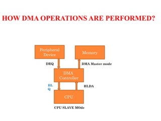
HOW DMA OPERATIONSARE PERFORMED?
Memory
DMA
Controller
CPU
Peripheral
Device
DRQ
HL
Q
HLDA
CPU SLAVE MOde
DMA Master mode
5.
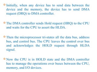
Initially, whenany device has to send data between the
device and the memory, the device has to send DMA
request (DRQ) to DMA controller.
The DMA controller sends Hold request (HRQ) to the CPU
and waits for the CPU to assert the HLDA.
Then the microprocessor tri-states all the data bus, address
bus, and control bus. The CPU leaves the control over bus
and acknowledges the HOLD request through HLDA
signal.
Now the CPU is in HOLD state and the DMA controller
has to manage the operations over buses between the CPU,
memory, and I/O devices.
6.
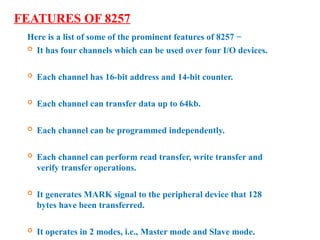
FEATURES OF 8257
Hereis a list of some of the prominent features of 8257 −
It has four channels which can be used over four I/O devices.
Each channel has 16-bit address and 14-bit counter.
Each channel can transfer data up to 64kb.
Each channel can be programmed independently.
Each channel can perform read transfer, write transfer and
verify transfer operations.
It generates MARK signal to the peripheral device that 128
bytes have been transferred.
It operates in 2 modes, i.e., Master mode and Slave mode.
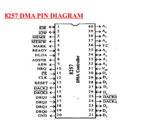
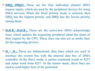
DRQ0−DRQ3: Theseare the four individual channel DMA
request inputs, which are used by the peripheral devices for using
DMA services. When the fixed priority mode is selected, then
DRQ0 has the highest priority and DRQ3 has the lowest priority
among them.
DACKo−DACK3: These are the active-low DMA acknowledge
lines, which updates the requesting peripheral about the status of
their request by the CPU. These lines can also act as strobe lines
for the requesting devices.
Do − D7: These are bidirectional, data lines which are used to
interface the system bus with the internal data bus of DMA
controller. In the Slave mode, it carries command words to 8257
and status word from 8257. In the master mode, these lines are
used to send higher byte of the generated
10.
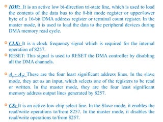
IOW: Itis an active low bi-direction tri-state line, which is used to load
the contents of the data bus to the 8-bit mode register or upper/lower
byte of a 16-bit DMA address register or terminal count register. In the
master mode, it is used to load the data to the peripheral devices during
DMA memory read cycle.
CLK: It is a clock frequency signal which is required for the internal
operation of 8257.
RESET: This signal is used to RESET the DMA controller by disabling
all the DMA channels.
Ao - A3: These are the four least significant address lines. In the slave
mode, they act as an input, which selects one of the registers to be read
or written. In the master mode, they are the four least significant
memory address output lines generated by 8257.
CS: It is an active-low chip select line. In the Slave mode, it enables the
read/write operations to/from 8257. In the master mode, it disables the
read/write operations to/from 8257.
11.
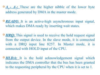
A4 -A7: These are the higher nibble of the lower byte
address generated by DMA in the master mode.
READY: It is an active-high asynchronous input signal,
which makes DMA ready by inserting wait states.
HRQ: This signal is used to receive the hold request signal
from the output device. In the slave mode, it is connected
with a DRQ input line 8257. In Master mode, it is
connected with HOLD input of the CPU.
HLDA: It is the hold acknowledgement signal which
indicates the DMA controller that the bus has been granted
to the requesting peripheral by the CPU when it is set to 1.
12.
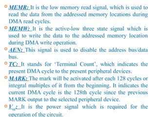
MEMR: Itis the low memory read signal, which is used to
read the data from the addressed memory locations during
DMA read cycles.
MEMW: It is the active-low three state signal which is
used to write the data to the addressed memory location
during DMA write operation.
AEN: This signal is used to disable the address bus/data
bus.
TC: It stands for ‘Terminal Count’, which indicates the
present DMA cycle to the present peripheral devices.
MARK: The mark will be activated after each 128 cycles or
integral multiples of it from the beginning. It indicates the
current DMA cycle is the 128th cycle since the previous
MARK output to the selected peripheral device.
Vcc: It is the power signal which is required for the
operation of the circuit.
13.
DIRECT MEMORY ACCESSADVANTAGES
AND DISADVANTAGES
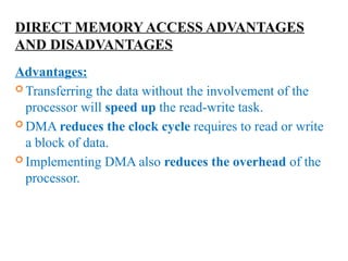
Advantages:
Transferring the data without the involvement of the
processor will speed up the read-write task.
DMA reduces the clock cycle requires to read or write
a block of data.
Implementing DMA also reduces the overhead of the
processor.
14.
DIRECT MEMORY ACCESSADVANTAGES
AND DISADVANTAGES
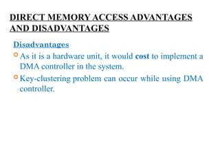
Disadvantages
As it is a hardware unit, it would cost to implement a
DMA controller in the system.
Key-clustering problem can occur while using DMA
controller.


![Chapter2_fault tolerance [Compatibility Mode].pdf](https://cdn.slidesharecdn.com/ss_thumbnails/chapter2faulttolerancecompatibilitymode-241007004857-8eb7d95f-thumbnail.jpg?width=640&height=640&fit=bounds)