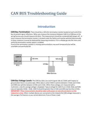
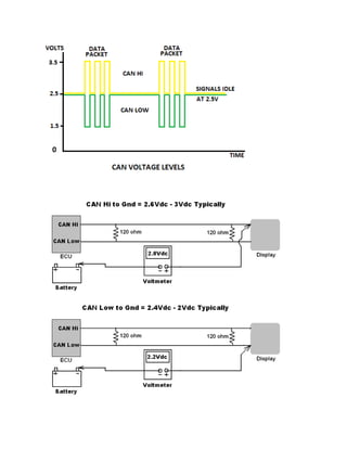
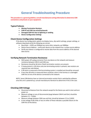
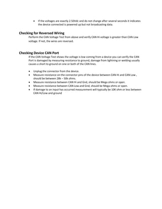
SlideShare a Scribd company logo
CAN BUS Troubleshooting Guide
Introduction
CAN Bus Termination: There should be a 120 ohm termination resistor located at each end of the
bus to prevent signal reflections. When you measure the resistance between CAN hi to CAN low on the
wiring harness you should measure 60 ohms. This measurement should be conducted with power off. In
some instances the termination resistor is located inside the Device and may be switched electronically.
In these instances it cannot be detected by measuring resistance, if it is a display go into the menu and
verify the termination resistor option is enabled.
If one of the termination resistors is missing communications may work temporarily but will be
unreliable and eventually fail.
CAN Bus Voltage Levels: The CAN bus data Low and HI signals idle at 2.5VDC with respect to
ground when there is no active data. When data is active CAN Hi switches between 2.5Vdc and 3.5Vdc
and CAN Low switches between 2.5Vdc and 1.5Vdc. When these voltages are measured with a
multimeter, only the average voltage is displayed. Typical voltage for CAN HI are 2.6Vdc-3Vdc and CAN
Low are typically 2.4Vdc – 2Vdc. CAN Hi should be greater than 2.5Vdc and CAN Low less than 2.5Vdc.
IMPORTANT: These measurements should be taken with power on and only one device on the
network at a time. When multiple devices are connected on the network the CAN voltage measured is
the average of all devices so you cannot determine if one of those is bad.
0
General Troubleshooting Procedure
This procedure is a general guideline; consult manufacturers wiring information to determine CAN
connections and pinouts on your equipment.
Typical Failures
 Missing Termination Resistors
 CAN Hi and CAN Low wired backwards
 Damaged CAN Port due to lightning or welding
 Device Configuration Settings
Check Device Configuration Settings
If the device has configuration options via display menu, dip switch settings, jumper settings, or
software download verify the following are correct.
 Baud Rate – J1939 use 250Kbps but some other networks use 500Kbps
 Device Source Address – verify each device on the network has a unique source address
 Verify your device is configured to receive data from the source address of the desired
data source.
Verifying Network Termination Resistance
 With power off unplug connector from any device on the network and measure
resistance between CAN Hi and CAN Low.
 Resistance should be 60 ohms if both termination resistors are present.
 If measurement is 120 ohms only one terminating resistor is present, two resistors are
required (see note below).
 If 40 ohms is measured a third terminating resistor is installed and should be removed.
 If less than 40 ohms is measured there could be a short in the harness or a damaged
CAN Port of one of the devices connected to the network.
NOTE: Some CAN devices have an internal termination resistor that is switched by software
once the unit is powered up, consult manufactures literature to determine if this is the case.
Checking CAN Voltage
 Disconnect all devices from the network except for the Device you wish to test and turn
power on.
 Measure voltage on any of disconnected plugs between CAN Hi and Gnd, should be
between 2.5 – 3.0Vdc.
 Measure voltage between CAN Low and Gnd, should be between 2.5 to 2.0VDC.
 A low voltage of @1.4Vdc or less on either of these indicates a possible failure on the
CAN Port of the device.
 If the voltages are exactly 2.50Vdc and do not change after several seconds it indicates
the device connected is powered up but not broadcasting data.
Checking for Reversed Wiring
Perform the CAN Voltage Test from above and verify CAN Hi voltage is greater than CAN Low
voltage. If not, the wires are reversed.
Checking Device CAN Port
If the CAN Voltage Test shows the voltage is low coming from a device you can verify the CAN
Port is damaged by measuring resistance to ground, damage from lightning or welding usually
causes a short to ground on one or both of the CAN lines.
 Unplug the connector from the device.
 Measure resistance on the connector pins of the device between CAN Hi and CAN Low ,
should be between 28k – 50k ohms.
 Measure resistance between CAN Hi and Gnd, should be Mega ohms or open.
 Measure resistance between CAN Low and Gnd, should be Mega ohms or open.
 If damage to an input has occurred measurement will typically be 10K ohm or less between
CAN Hi/Low and ground

More Related Content

What's hot

Controller area network (can bus)
Controller area network (can bus)Controller area network (can bus)
Controller area network (can bus)
nassim unused
 
Can bus
Can busCan bus
Can bus
Rucha Pupala
 
Can Protocol For Automobiles
Can Protocol For AutomobilesCan Protocol For Automobiles
Can Protocol For Automobiles
Sofcon India Pvt Ltd.
 
CAN Bus
CAN BusCAN Bus
Can basic
Can basicCan basic
Can basic
RobertsMax
 
AMBA_APB_pst
AMBA_APB_pstAMBA_APB_pst
AMBA_APB_pst
Bynaboina Krishna
 
Can Bus communication Protocol
Can Bus communication ProtocolCan Bus communication Protocol
Can Bus communication Protocol
Pedro Campana Cueto
 
CAN F28x
CAN F28xCAN F28x
Controller Area Network (CAN) Protocol || Automotive Electronics || Hariharan K
Controller Area Network (CAN) Protocol || Automotive Electronics || Hariharan KController Area Network (CAN) Protocol || Automotive Electronics || Hariharan K
Controller Area Network (CAN) Protocol || Automotive Electronics || Hariharan K
Hariharan Krishnan
 
Controller Area Network(CAN)
Controller Area Network(CAN)Controller Area Network(CAN)
Controller Area Network(CAN)
Ashutosh Bhardwaj
 
Automotive bus technologies
Automotive bus technologiesAutomotive bus technologies
Automotive bus technologies
Radwa Tarek
 
Controller area network protocol
Controller area network protocolController area network protocol
Controller area network protocol
Sneha Nalla
 
can bus theory solution
can bus theory solutioncan bus theory solution
can bus theory solution
Md. Mashiur Rahman
 
A SEMINAR REPORT ON CAN BUS PROTOCOL
A SEMINAR REPORT ON CAN BUS PROTOCOLA SEMINAR REPORT ON CAN BUS PROTOCOL
A SEMINAR REPORT ON CAN BUS PROTOCOL
Abhinaw Tiwari
 
Comparison Between CAN and CAN FD
Comparison Between CAN and CAN FDComparison Between CAN and CAN FD
Comparison Between CAN and CAN FD
Embitel Technologies (I) PVT LTD
 
LIN protocol description
LIN protocol descriptionLIN protocol description
LIN protocol description
sonu kumar suman
 
Controller area network (CAN bus) ppt
Controller area network (CAN bus) pptController area network (CAN bus) ppt
Controller area network (CAN bus) ppt
Raziuddin Khazi
 
Controller area network
Controller area networkController area network
Controller area network
sanaz nouri
 
CAN (Controller Area Network)
CAN (Controller Area Network)CAN (Controller Area Network)
CAN (Controller Area Network)
Ajay Sukruth
 
Coding
CodingCoding
Coding
Dayal Sati
 

What's hot (20)

Controller area network (can bus)
Controller area network (can bus)Controller area network (can bus)
Controller area network (can bus)
 
Can bus
Can busCan bus
Can bus
 
Can Protocol For Automobiles
Can Protocol For AutomobilesCan Protocol For Automobiles
Can Protocol For Automobiles
 
CAN Bus
CAN BusCAN Bus
CAN Bus
 
Can basic
Can basicCan basic
Can basic
 
AMBA_APB_pst
AMBA_APB_pstAMBA_APB_pst
AMBA_APB_pst
 
Can Bus communication Protocol
Can Bus communication ProtocolCan Bus communication Protocol
Can Bus communication Protocol
 
CAN F28x
CAN F28xCAN F28x
CAN F28x
 
Controller Area Network (CAN) Protocol || Automotive Electronics || Hariharan K
Controller Area Network (CAN) Protocol || Automotive Electronics || Hariharan KController Area Network (CAN) Protocol || Automotive Electronics || Hariharan K
Controller Area Network (CAN) Protocol || Automotive Electronics || Hariharan K
 
Controller Area Network(CAN)
Controller Area Network(CAN)Controller Area Network(CAN)
Controller Area Network(CAN)
 
Automotive bus technologies
Automotive bus technologiesAutomotive bus technologies
Automotive bus technologies
 
Controller area network protocol
Controller area network protocolController area network protocol
Controller area network protocol
 
can bus theory solution
can bus theory solutioncan bus theory solution
can bus theory solution
 
A SEMINAR REPORT ON CAN BUS PROTOCOL
A SEMINAR REPORT ON CAN BUS PROTOCOLA SEMINAR REPORT ON CAN BUS PROTOCOL
A SEMINAR REPORT ON CAN BUS PROTOCOL
 
Comparison Between CAN and CAN FD
Comparison Between CAN and CAN FDComparison Between CAN and CAN FD
Comparison Between CAN and CAN FD
 
LIN protocol description
LIN protocol descriptionLIN protocol description
LIN protocol description
 
Controller area network (CAN bus) ppt
Controller area network (CAN bus) pptController area network (CAN bus) ppt
Controller area network (CAN bus) ppt
 
Controller area network
Controller area networkController area network
Controller area network
 
CAN (Controller Area Network)
CAN (Controller Area Network)CAN (Controller Area Network)
CAN (Controller Area Network)
 
Coding
CodingCoding
Coding
 

Similar to Can bus troubleshootingrevb

Rectifier Operations & Maintenance - Don Olson - 2.4.2020
Rectifier Operations & Maintenance - Don Olson - 2.4.2020Rectifier Operations & Maintenance - Don Olson - 2.4.2020
Rectifier Operations & Maintenance - Don Olson - 2.4.2020
nacetwincities
 
lem_procon-plus_400p_750p_1000p_1250p_1500p_1800p_2200p_adjustments_sch.pdf
lem_procon-plus_400p_750p_1000p_1250p_1500p_1800p_2200p_adjustments_sch.pdflem_procon-plus_400p_750p_1000p_1250p_1500p_1800p_2200p_adjustments_sch.pdf
lem_procon-plus_400p_750p_1000p_1250p_1500p_1800p_2200p_adjustments_sch.pdf
NestorMartin8
 
lm3914.pdf
lm3914.pdflm3914.pdf
Adi jul1311
Adi jul1311Adi jul1311
D:\Edtech 2\Day5 Lesson11 N0ss
D:\Edtech 2\Day5 Lesson11 N0ssD:\Edtech 2\Day5 Lesson11 N0ss
D:\Edtech 2\Day5 Lesson11 N0ss
Arnold Dela Peña
 
Design and fabrication of over voltage relay
Design and fabrication of over voltage relay Design and fabrication of over voltage relay
Design and fabrication of over voltage relay
Prem Kumar
 
pe lab manual
pe lab manualpe lab manual
pe lab manual
saisureshnaidu
 
Advanced motion controls azb20a20
Advanced motion controls azb20a20Advanced motion controls azb20a20
Advanced motion controls azb20a20
Electromate
 
Constant Current Regulator for Driving LEDs
Constant Current Regulator for Driving LEDsConstant Current Regulator for Driving LEDs
Constant Current Regulator for Driving LEDs
Premier Farnell
 
Bender rc48 c
Bender rc48 cBender rc48 c
Ncp1032 d
Ncp1032 dNcp1032 d
EMI Surge Protection Circuit Analysis
EMI Surge Protection Circuit AnalysisEMI Surge Protection Circuit Analysis
EMI Surge Protection Circuit Analysis
RekaNext Capital
 
Hướng dẫn sử dụng máy kiểm tra pin ắc quy Tenmars TM-6002
Hướng dẫn sử dụng máy kiểm tra pin ắc quy Tenmars TM-6002Hướng dẫn sử dụng máy kiểm tra pin ắc quy Tenmars TM-6002
Hướng dẫn sử dụng máy kiểm tra pin ắc quy Tenmars TM-6002
Tenmars Việt Nam
 
Original High Voltage Isolation IC ACS710T KLA-12CB 710T SOP-16 New
Original High Voltage Isolation IC ACS710T KLA-12CB 710T SOP-16 NewOriginal High Voltage Isolation IC ACS710T KLA-12CB 710T SOP-16 New
Original High Voltage Isolation IC ACS710T KLA-12CB 710T SOP-16 New
AUTHELECTRONIC
 
LTC1540 Ultra-Low Power Comparator
LTC1540 Ultra-Low Power ComparatorLTC1540 Ultra-Low Power Comparator
LTC1540 Ultra-Low Power Comparator
Premier Farnell
 
Mains operated under voltage over voltage trip switch
Mains operated under voltage over voltage trip switchMains operated under voltage over voltage trip switch
Mains operated under voltage over voltage trip switch
Edgefxkits & Solutions
 
Study on 12-/14-/16-Bit, Octal-Channel, DAC
Study on 12-/14-/16-Bit, Octal-Channel, DACStudy on 12-/14-/16-Bit, Octal-Channel, DAC
Study on 12-/14-/16-Bit, Octal-Channel, DAC
Premier Farnell
 
Detection of fault location in underground cable using arduino
Detection of fault location in underground cable using arduinoDetection of fault location in underground cable using arduino
Detection of fault location in underground cable using arduino
Chirag Lakhani
 
Fieldbus wiring guide
Fieldbus wiring guideFieldbus wiring guide
Fieldbus wiring guide
Mohamed A Hakim
 
XLSEMI XL140 2A 380KHz 18V Buck DC to DC Converter
XLSEMI XL140 2A 380KHz 18V Buck DC to DC ConverterXLSEMI XL140 2A 380KHz 18V Buck DC to DC Converter
XLSEMI XL140 2A 380KHz 18V Buck DC to DC Converter
degarden
 

Similar to Can bus troubleshootingrevb (20)

Rectifier Operations & Maintenance - Don Olson - 2.4.2020
Rectifier Operations & Maintenance - Don Olson - 2.4.2020Rectifier Operations & Maintenance - Don Olson - 2.4.2020
Rectifier Operations & Maintenance - Don Olson - 2.4.2020
 
lem_procon-plus_400p_750p_1000p_1250p_1500p_1800p_2200p_adjustments_sch.pdf
lem_procon-plus_400p_750p_1000p_1250p_1500p_1800p_2200p_adjustments_sch.pdflem_procon-plus_400p_750p_1000p_1250p_1500p_1800p_2200p_adjustments_sch.pdf
lem_procon-plus_400p_750p_1000p_1250p_1500p_1800p_2200p_adjustments_sch.pdf
 
lm3914.pdf
lm3914.pdflm3914.pdf
lm3914.pdf
 
Adi jul1311
Adi jul1311Adi jul1311
Adi jul1311
 
D:\Edtech 2\Day5 Lesson11 N0ss
D:\Edtech 2\Day5 Lesson11 N0ssD:\Edtech 2\Day5 Lesson11 N0ss
D:\Edtech 2\Day5 Lesson11 N0ss
 
Design and fabrication of over voltage relay
Design and fabrication of over voltage relay Design and fabrication of over voltage relay
Design and fabrication of over voltage relay
 
pe lab manual
pe lab manualpe lab manual
pe lab manual
 
Advanced motion controls azb20a20
Advanced motion controls azb20a20Advanced motion controls azb20a20
Advanced motion controls azb20a20
 
Constant Current Regulator for Driving LEDs
Constant Current Regulator for Driving LEDsConstant Current Regulator for Driving LEDs
Constant Current Regulator for Driving LEDs
 
Bender rc48 c
Bender rc48 cBender rc48 c
Bender rc48 c
 
Ncp1032 d
Ncp1032 dNcp1032 d
Ncp1032 d
 
EMI Surge Protection Circuit Analysis
EMI Surge Protection Circuit AnalysisEMI Surge Protection Circuit Analysis
EMI Surge Protection Circuit Analysis
 
Hướng dẫn sử dụng máy kiểm tra pin ắc quy Tenmars TM-6002
Hướng dẫn sử dụng máy kiểm tra pin ắc quy Tenmars TM-6002Hướng dẫn sử dụng máy kiểm tra pin ắc quy Tenmars TM-6002
Hướng dẫn sử dụng máy kiểm tra pin ắc quy Tenmars TM-6002
 
Original High Voltage Isolation IC ACS710T KLA-12CB 710T SOP-16 New
Original High Voltage Isolation IC ACS710T KLA-12CB 710T SOP-16 NewOriginal High Voltage Isolation IC ACS710T KLA-12CB 710T SOP-16 New
Original High Voltage Isolation IC ACS710T KLA-12CB 710T SOP-16 New
 
LTC1540 Ultra-Low Power Comparator
LTC1540 Ultra-Low Power ComparatorLTC1540 Ultra-Low Power Comparator
LTC1540 Ultra-Low Power Comparator
 
Mains operated under voltage over voltage trip switch
Mains operated under voltage over voltage trip switchMains operated under voltage over voltage trip switch
Mains operated under voltage over voltage trip switch
 
Study on 12-/14-/16-Bit, Octal-Channel, DAC
Study on 12-/14-/16-Bit, Octal-Channel, DACStudy on 12-/14-/16-Bit, Octal-Channel, DAC
Study on 12-/14-/16-Bit, Octal-Channel, DAC
 
Detection of fault location in underground cable using arduino
Detection of fault location in underground cable using arduinoDetection of fault location in underground cable using arduino
Detection of fault location in underground cable using arduino
 
Fieldbus wiring guide
Fieldbus wiring guideFieldbus wiring guide
Fieldbus wiring guide
 
XLSEMI XL140 2A 380KHz 18V Buck DC to DC Converter
XLSEMI XL140 2A 380KHz 18V Buck DC to DC ConverterXLSEMI XL140 2A 380KHz 18V Buck DC to DC Converter
XLSEMI XL140 2A 380KHz 18V Buck DC to DC Converter
 

Recently uploaded

Generative AI leverages algorithms to create various forms of content
Generative AI leverages algorithms to create various forms of contentGenerative AI leverages algorithms to create various forms of content
Generative AI leverages algorithms to create various forms of content
Hitesh Mohapatra
 
Electric vehicle and photovoltaic advanced roles in enhancing the financial p...
Electric vehicle and photovoltaic advanced roles in enhancing the financial p...Electric vehicle and photovoltaic advanced roles in enhancing the financial p...
Electric vehicle and photovoltaic advanced roles in enhancing the financial p...
IJECEIAES
 
2. Operations Strategy in a Global Environment.ppt
2. Operations Strategy in a Global Environment.ppt2. Operations Strategy in a Global Environment.ppt
2. Operations Strategy in a Global Environment.ppt
PuktoonEngr
 
digital fundamental by Thomas L.floydl.pdf
digital fundamental by Thomas L.floydl.pdfdigital fundamental by Thomas L.floydl.pdf
digital fundamental by Thomas L.floydl.pdf
drwaing
 
Modelagem de um CSTR com reação endotermica.pdf
Modelagem de um CSTR com reação endotermica.pdfModelagem de um CSTR com reação endotermica.pdf
Modelagem de um CSTR com reação endotermica.pdf
camseq
 
Wearable antenna for antenna applications
Wearable antenna for antenna applicationsWearable antenna for antenna applications
Wearable antenna for antenna applications
Madhumitha Jayaram
 
DEEP LEARNING FOR SMART GRID INTRUSION DETECTION: A HYBRID CNN-LSTM-BASED MODEL
DEEP LEARNING FOR SMART GRID INTRUSION DETECTION: A HYBRID CNN-LSTM-BASED MODELDEEP LEARNING FOR SMART GRID INTRUSION DETECTION: A HYBRID CNN-LSTM-BASED MODEL
DEEP LEARNING FOR SMART GRID INTRUSION DETECTION: A HYBRID CNN-LSTM-BASED MODEL
gerogepatton
 
basic-wireline-operations-course-mahmoud-f-radwan.pdf
basic-wireline-operations-course-mahmoud-f-radwan.pdfbasic-wireline-operations-course-mahmoud-f-radwan.pdf
basic-wireline-operations-course-mahmoud-f-radwan.pdf
NidhalKahouli2
 
ML Based Model for NIDS MSc Updated Presentation.v2.pptx
ML Based Model for NIDS MSc Updated Presentation.v2.pptxML Based Model for NIDS MSc Updated Presentation.v2.pptx
ML Based Model for NIDS MSc Updated Presentation.v2.pptx
JamalHussainArman
 
Recycled Concrete Aggregate in Construction Part III
Recycled Concrete Aggregate in Construction Part IIIRecycled Concrete Aggregate in Construction Part III
Recycled Concrete Aggregate in Construction Part III
Aditya Rajan Patra
 
Properties Railway Sleepers and Test.pptx
Properties Railway Sleepers and Test.pptxProperties Railway Sleepers and Test.pptx
Properties Railway Sleepers and Test.pptx
MDSABBIROJJAMANPAYEL
 
Presentation of IEEE Slovenia CIS (Computational Intelligence Society) Chapte...
Presentation of IEEE Slovenia CIS (Computational Intelligence Society) Chapte...Presentation of IEEE Slovenia CIS (Computational Intelligence Society) Chapte...
Presentation of IEEE Slovenia CIS (Computational Intelligence Society) Chapte...
University of Maribor
 
Advanced control scheme of doubly fed induction generator for wind turbine us...
Advanced control scheme of doubly fed induction generator for wind turbine us...Advanced control scheme of doubly fed induction generator for wind turbine us...
Advanced control scheme of doubly fed induction generator for wind turbine us...
IJECEIAES
 
[JPP-1] - (JEE 3.0) - Kinematics 1D - 14th May..pdf
[JPP-1] - (JEE 3.0) - Kinematics 1D - 14th May..pdf[JPP-1] - (JEE 3.0) - Kinematics 1D - 14th May..pdf
[JPP-1] - (JEE 3.0) - Kinematics 1D - 14th May..pdf
awadeshbabu
 
spirit beverages ppt without graphics.pptx
spirit beverages ppt without graphics.pptxspirit beverages ppt without graphics.pptx
spirit beverages ppt without graphics.pptx
Madan Karki
 
132/33KV substation case study Presentation
132/33KV substation case study Presentation132/33KV substation case study Presentation
132/33KV substation case study Presentation
kandramariana6
 
Literature Review Basics and Understanding Reference Management.pptx
Literature Review Basics and Understanding Reference Management.pptxLiterature Review Basics and Understanding Reference Management.pptx
Literature Review Basics and Understanding Reference Management.pptx
Dr Ramhari Poudyal
 
KuberTENes Birthday Bash Guadalajara - K8sGPT first impressions
KuberTENes Birthday Bash Guadalajara - K8sGPT first impressionsKuberTENes Birthday Bash Guadalajara - K8sGPT first impressions
KuberTENes Birthday Bash Guadalajara - K8sGPT first impressions
Victor Morales
 
6th International Conference on Machine Learning & Applications (CMLA 2024)
6th International Conference on Machine Learning & Applications (CMLA 2024)6th International Conference on Machine Learning & Applications (CMLA 2024)
6th International Conference on Machine Learning & Applications (CMLA 2024)
ClaraZara1
 
Harnessing WebAssembly for Real-time Stateless Streaming Pipelines
Harnessing WebAssembly for Real-time Stateless Streaming PipelinesHarnessing WebAssembly for Real-time Stateless Streaming Pipelines
Harnessing WebAssembly for Real-time Stateless Streaming Pipelines
Christina Lin
 

Recently uploaded (20)

Generative AI leverages algorithms to create various forms of content
Generative AI leverages algorithms to create various forms of contentGenerative AI leverages algorithms to create various forms of content
Generative AI leverages algorithms to create various forms of content
 
Electric vehicle and photovoltaic advanced roles in enhancing the financial p...
Electric vehicle and photovoltaic advanced roles in enhancing the financial p...Electric vehicle and photovoltaic advanced roles in enhancing the financial p...
Electric vehicle and photovoltaic advanced roles in enhancing the financial p...
 
2. Operations Strategy in a Global Environment.ppt
2. Operations Strategy in a Global Environment.ppt2. Operations Strategy in a Global Environment.ppt
2. Operations Strategy in a Global Environment.ppt
 
digital fundamental by Thomas L.floydl.pdf
digital fundamental by Thomas L.floydl.pdfdigital fundamental by Thomas L.floydl.pdf
digital fundamental by Thomas L.floydl.pdf
 
Modelagem de um CSTR com reação endotermica.pdf
Modelagem de um CSTR com reação endotermica.pdfModelagem de um CSTR com reação endotermica.pdf
Modelagem de um CSTR com reação endotermica.pdf
 
Wearable antenna for antenna applications
Wearable antenna for antenna applicationsWearable antenna for antenna applications
Wearable antenna for antenna applications
 
DEEP LEARNING FOR SMART GRID INTRUSION DETECTION: A HYBRID CNN-LSTM-BASED MODEL
DEEP LEARNING FOR SMART GRID INTRUSION DETECTION: A HYBRID CNN-LSTM-BASED MODELDEEP LEARNING FOR SMART GRID INTRUSION DETECTION: A HYBRID CNN-LSTM-BASED MODEL
DEEP LEARNING FOR SMART GRID INTRUSION DETECTION: A HYBRID CNN-LSTM-BASED MODEL
 
basic-wireline-operations-course-mahmoud-f-radwan.pdf
basic-wireline-operations-course-mahmoud-f-radwan.pdfbasic-wireline-operations-course-mahmoud-f-radwan.pdf
basic-wireline-operations-course-mahmoud-f-radwan.pdf
 
ML Based Model for NIDS MSc Updated Presentation.v2.pptx
ML Based Model for NIDS MSc Updated Presentation.v2.pptxML Based Model for NIDS MSc Updated Presentation.v2.pptx
ML Based Model for NIDS MSc Updated Presentation.v2.pptx
 
Recycled Concrete Aggregate in Construction Part III
Recycled Concrete Aggregate in Construction Part IIIRecycled Concrete Aggregate in Construction Part III
Recycled Concrete Aggregate in Construction Part III
 
Properties Railway Sleepers and Test.pptx
Properties Railway Sleepers and Test.pptxProperties Railway Sleepers and Test.pptx
Properties Railway Sleepers and Test.pptx
 
Presentation of IEEE Slovenia CIS (Computational Intelligence Society) Chapte...
Presentation of IEEE Slovenia CIS (Computational Intelligence Society) Chapte...Presentation of IEEE Slovenia CIS (Computational Intelligence Society) Chapte...
Presentation of IEEE Slovenia CIS (Computational Intelligence Society) Chapte...
 
Advanced control scheme of doubly fed induction generator for wind turbine us...
Advanced control scheme of doubly fed induction generator for wind turbine us...Advanced control scheme of doubly fed induction generator for wind turbine us...
Advanced control scheme of doubly fed induction generator for wind turbine us...
 
[JPP-1] - (JEE 3.0) - Kinematics 1D - 14th May..pdf
[JPP-1] - (JEE 3.0) - Kinematics 1D - 14th May..pdf[JPP-1] - (JEE 3.0) - Kinematics 1D - 14th May..pdf
[JPP-1] - (JEE 3.0) - Kinematics 1D - 14th May..pdf
 
spirit beverages ppt without graphics.pptx
spirit beverages ppt without graphics.pptxspirit beverages ppt without graphics.pptx
spirit beverages ppt without graphics.pptx
 
132/33KV substation case study Presentation
132/33KV substation case study Presentation132/33KV substation case study Presentation
132/33KV substation case study Presentation
 
Literature Review Basics and Understanding Reference Management.pptx
Literature Review Basics and Understanding Reference Management.pptxLiterature Review Basics and Understanding Reference Management.pptx
Literature Review Basics and Understanding Reference Management.pptx
 
KuberTENes Birthday Bash Guadalajara - K8sGPT first impressions
KuberTENes Birthday Bash Guadalajara - K8sGPT first impressionsKuberTENes Birthday Bash Guadalajara - K8sGPT first impressions
KuberTENes Birthday Bash Guadalajara - K8sGPT first impressions
 
6th International Conference on Machine Learning & Applications (CMLA 2024)
6th International Conference on Machine Learning & Applications (CMLA 2024)6th International Conference on Machine Learning & Applications (CMLA 2024)
6th International Conference on Machine Learning & Applications (CMLA 2024)
 
Harnessing WebAssembly for Real-time Stateless Streaming Pipelines
Harnessing WebAssembly for Real-time Stateless Streaming PipelinesHarnessing WebAssembly for Real-time Stateless Streaming Pipelines
Harnessing WebAssembly for Real-time Stateless Streaming Pipelines
 

Can bus troubleshootingrevb

  • 1. CAN BUS Troubleshooting Guide Introduction CAN Bus Termination: There should be a 120 ohm termination resistor located at each end of the bus to prevent signal reflections. When you measure the resistance between CAN hi to CAN low on the wiring harness you should measure 60 ohms. This measurement should be conducted with power off. In some instances the termination resistor is located inside the Device and may be switched electronically. In these instances it cannot be detected by measuring resistance, if it is a display go into the menu and verify the termination resistor option is enabled. If one of the termination resistors is missing communications may work temporarily but will be unreliable and eventually fail. CAN Bus Voltage Levels: The CAN bus data Low and HI signals idle at 2.5VDC with respect to ground when there is no active data. When data is active CAN Hi switches between 2.5Vdc and 3.5Vdc and CAN Low switches between 2.5Vdc and 1.5Vdc. When these voltages are measured with a multimeter, only the average voltage is displayed. Typical voltage for CAN HI are 2.6Vdc-3Vdc and CAN Low are typically 2.4Vdc – 2Vdc. CAN Hi should be greater than 2.5Vdc and CAN Low less than 2.5Vdc. IMPORTANT: These measurements should be taken with power on and only one device on the network at a time. When multiple devices are connected on the network the CAN voltage measured is the average of all devices so you cannot determine if one of those is bad.
  • 2. 0
  • 3. General Troubleshooting Procedure This procedure is a general guideline; consult manufacturers wiring information to determine CAN connections and pinouts on your equipment. Typical Failures  Missing Termination Resistors  CAN Hi and CAN Low wired backwards  Damaged CAN Port due to lightning or welding  Device Configuration Settings Check Device Configuration Settings If the device has configuration options via display menu, dip switch settings, jumper settings, or software download verify the following are correct.  Baud Rate – J1939 use 250Kbps but some other networks use 500Kbps  Device Source Address – verify each device on the network has a unique source address  Verify your device is configured to receive data from the source address of the desired data source. Verifying Network Termination Resistance  With power off unplug connector from any device on the network and measure resistance between CAN Hi and CAN Low.  Resistance should be 60 ohms if both termination resistors are present.  If measurement is 120 ohms only one terminating resistor is present, two resistors are required (see note below).  If 40 ohms is measured a third terminating resistor is installed and should be removed.  If less than 40 ohms is measured there could be a short in the harness or a damaged CAN Port of one of the devices connected to the network. NOTE: Some CAN devices have an internal termination resistor that is switched by software once the unit is powered up, consult manufactures literature to determine if this is the case. Checking CAN Voltage  Disconnect all devices from the network except for the Device you wish to test and turn power on.  Measure voltage on any of disconnected plugs between CAN Hi and Gnd, should be between 2.5 – 3.0Vdc.  Measure voltage between CAN Low and Gnd, should be between 2.5 to 2.0VDC.  A low voltage of @1.4Vdc or less on either of these indicates a possible failure on the CAN Port of the device.
  • 4.  If the voltages are exactly 2.50Vdc and do not change after several seconds it indicates the device connected is powered up but not broadcasting data. Checking for Reversed Wiring Perform the CAN Voltage Test from above and verify CAN Hi voltage is greater than CAN Low voltage. If not, the wires are reversed. Checking Device CAN Port If the CAN Voltage Test shows the voltage is low coming from a device you can verify the CAN Port is damaged by measuring resistance to ground, damage from lightning or welding usually causes a short to ground on one or both of the CAN lines.  Unplug the connector from the device.  Measure resistance on the connector pins of the device between CAN Hi and CAN Low , should be between 28k – 50k ohms.  Measure resistance between CAN Hi and Gnd, should be Mega ohms or open.  Measure resistance between CAN Low and Gnd, should be Mega ohms or open.  If damage to an input has occurred measurement will typically be 10K ohm or less between CAN Hi/Low and ground