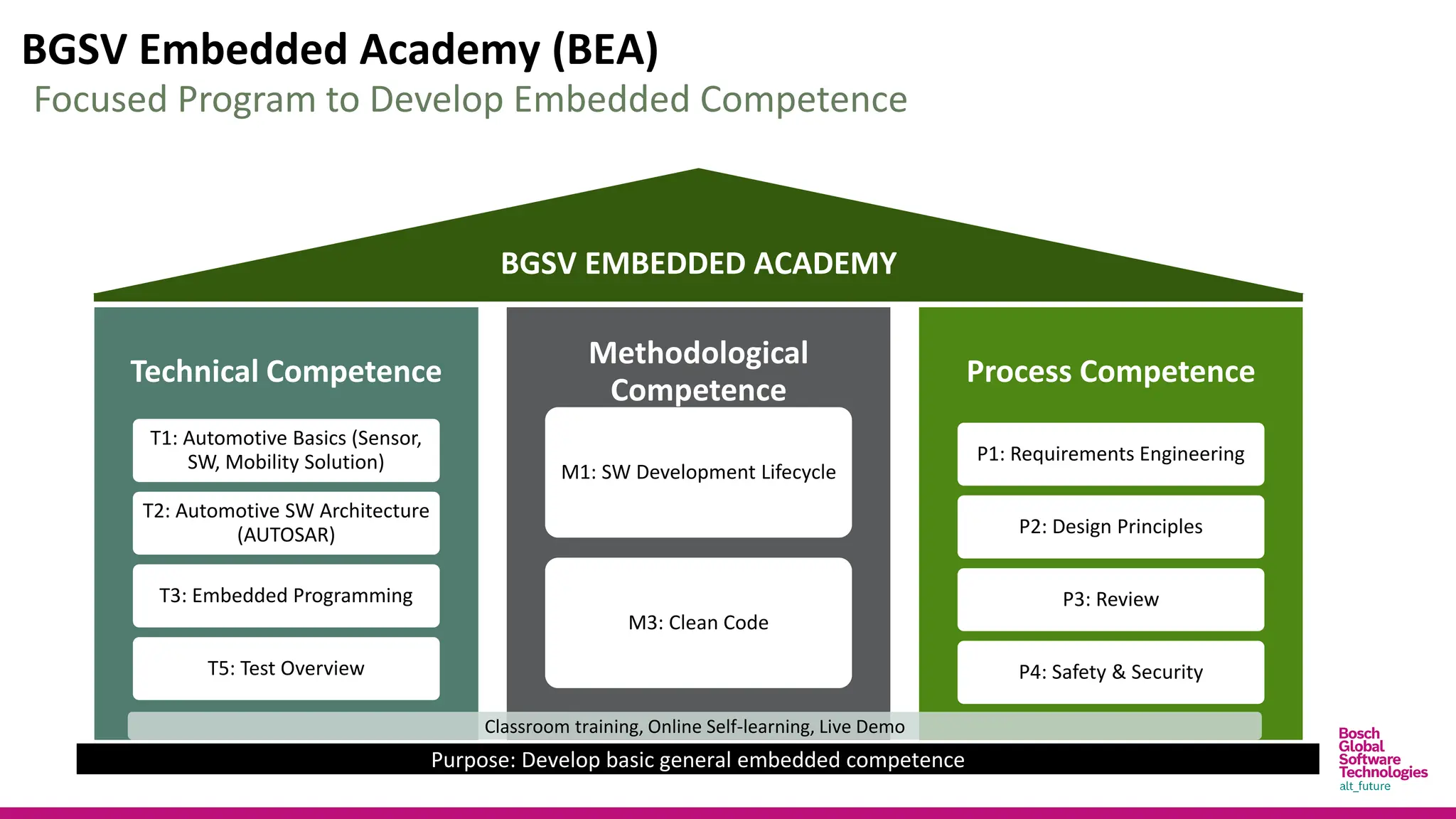
BGSV Embedded Academy(BEA)
Technical Competence
T1: Automotive Basics (Sensor,
SW, Mobility Solution)
T2: Automotive SW Architecture
(AUTOSAR)
T3: Embedded Programming
T5: Test Overview
Methodological
Competence
M1: SW Development Lifecycle
M3: Clean Code
Process Competence
P1: Requirements Engineering
P2: Design Principles
P3: Review
P4: Safety & Security
BGSV EMBEDDED ACADEMY
Purpose: Develop basic general embedded competence
Focused Program to Develop Embedded Competence
Classroom training, Online Self-learning, Live Demo
3.
Disclaimer
This slideis a part of BGSV Embedded Academy (BEA) program and only used for BEA training
purposes.
This slide is Bosch Global Software Technology Company Limited’s internal property. All rights
reserved, also regarding any disposal, exploitation, reproduction, editing, distribution as well
as in the event of applications for industrial property rights.
This slide has some copyright images and text, which belong to the respective organizations.
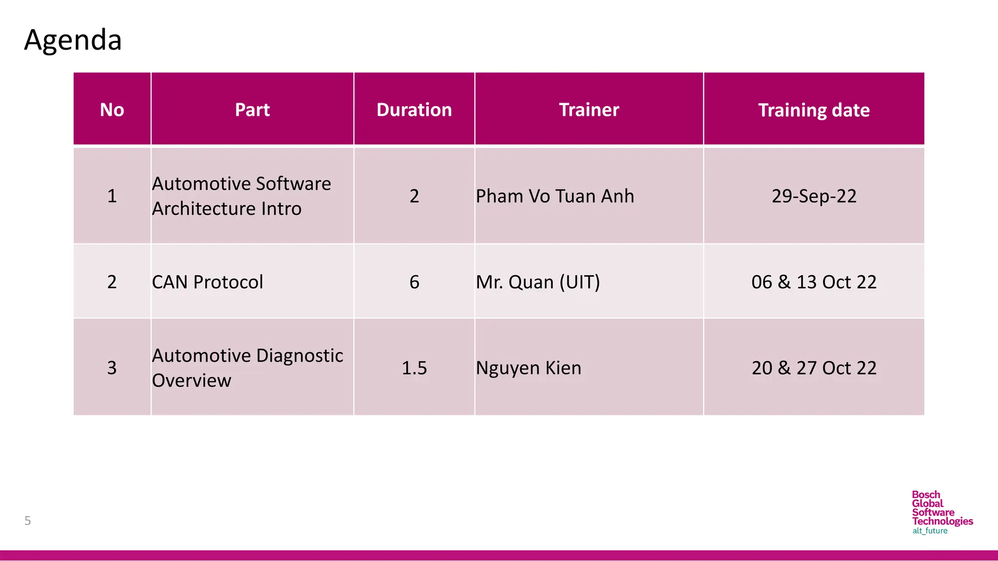
Agenda
5
No Part DurationTrainer Training date
1
Automotive Software
Architecture Intro
2 Pham Vo Tuan Anh 29-Sep-22
2 CAN Protocol 6 Mr. Quan (UIT) 06 & 13 Oct 22
3
Automotive Diagnostic
Overview
1.5 Nguyen Kien 20 & 27 Oct 22
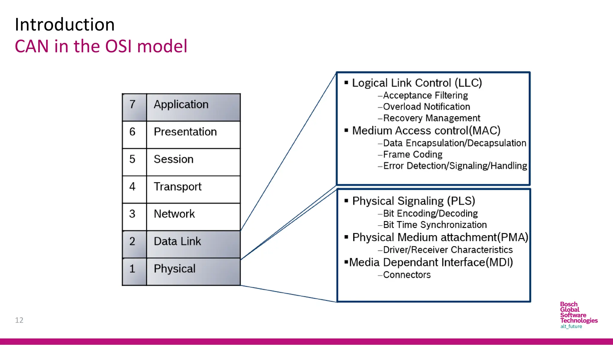
Introduction
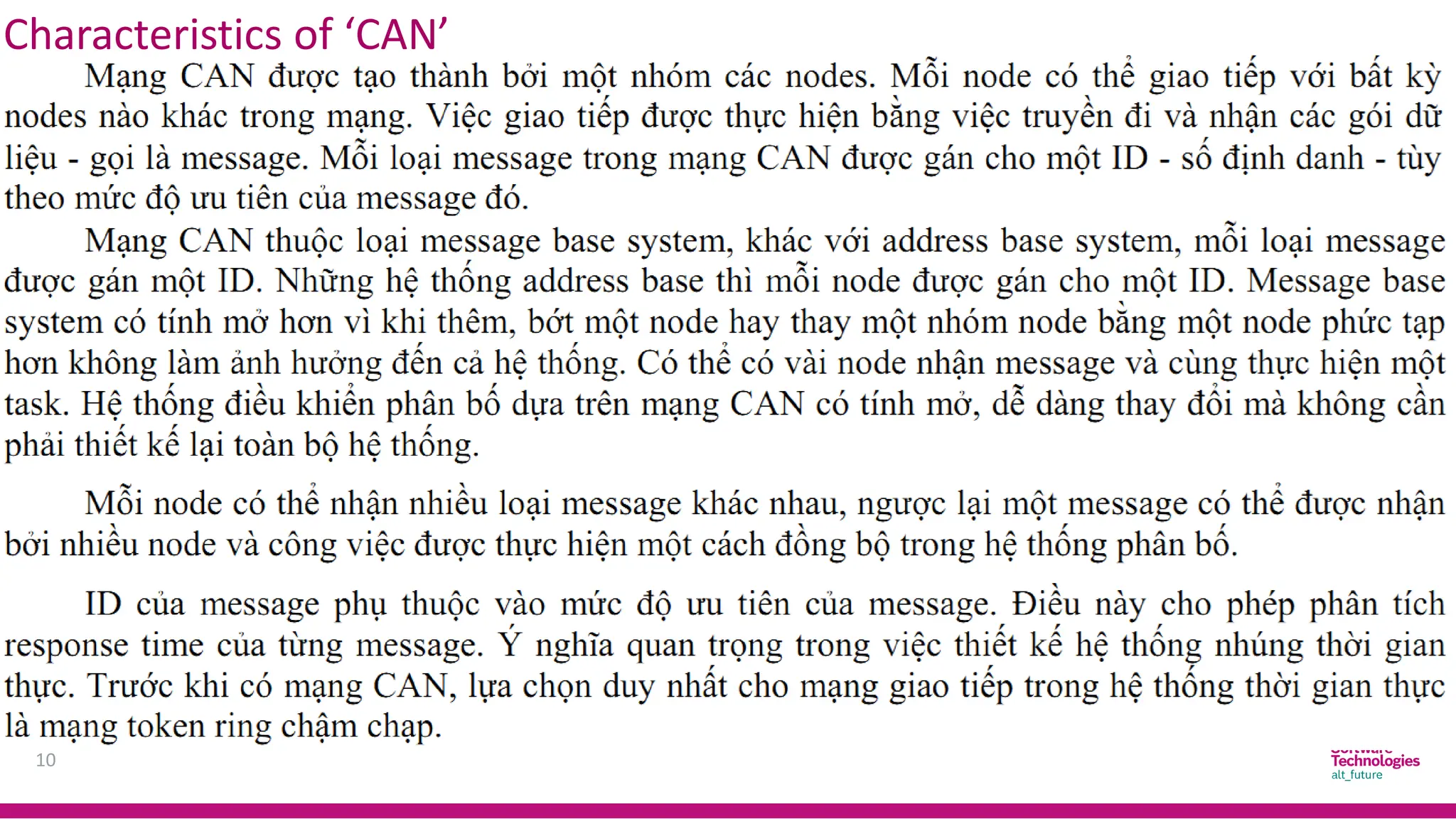
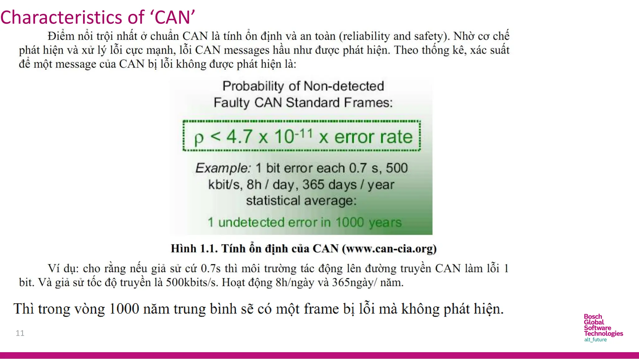
Characteristics of ‘CAN’
9
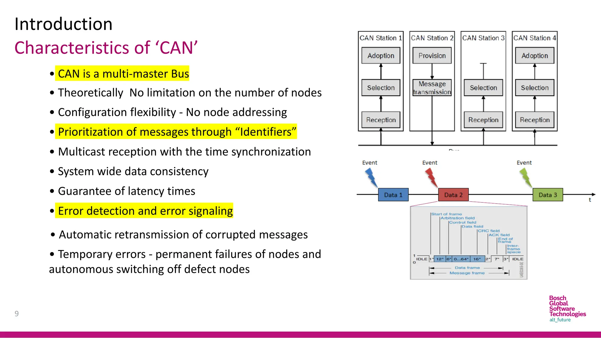
•CAN is a multi-master Bus
• Configuration flexibility - No node addressing
• Prioritization of messages through “Identifiers”
• Theoretically No limitation on the number of nodes
• Guarantee of latency times
• Multicast reception with the time synchronization
• System wide data consistency
• Error detection and error signaling
• Automatic retransmission of corrupted messages
• Temporary errors - permanent failures of nodes and
autonomous switching off defect nodes
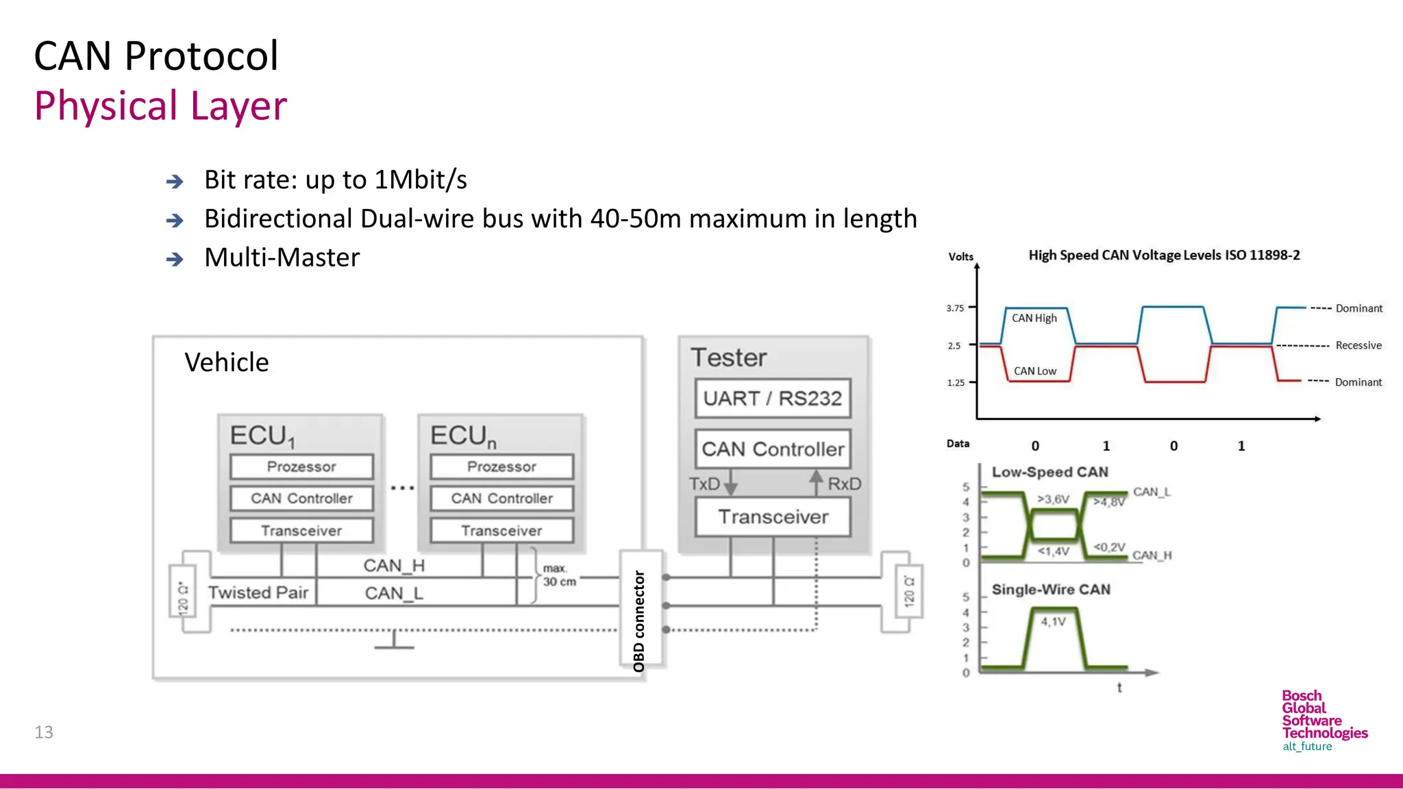
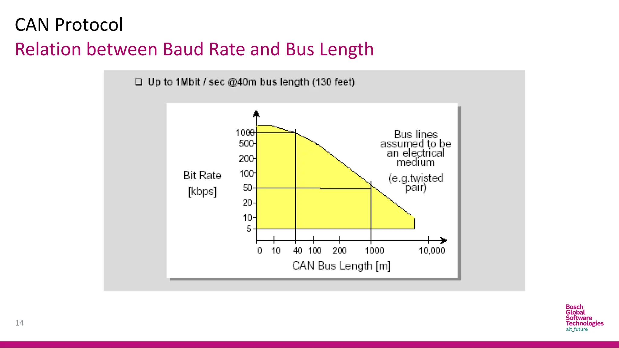
CAN Protocol
13
➔ Bitrate: up to 1Mbit/s
➔ Bidirectional Dual-wire bus with 40-50m maximum in length
➔ Multi-Master
Physical Layer
Vehicle
OBD
connector
CAN bus level
Volt
CAN Protocol
15
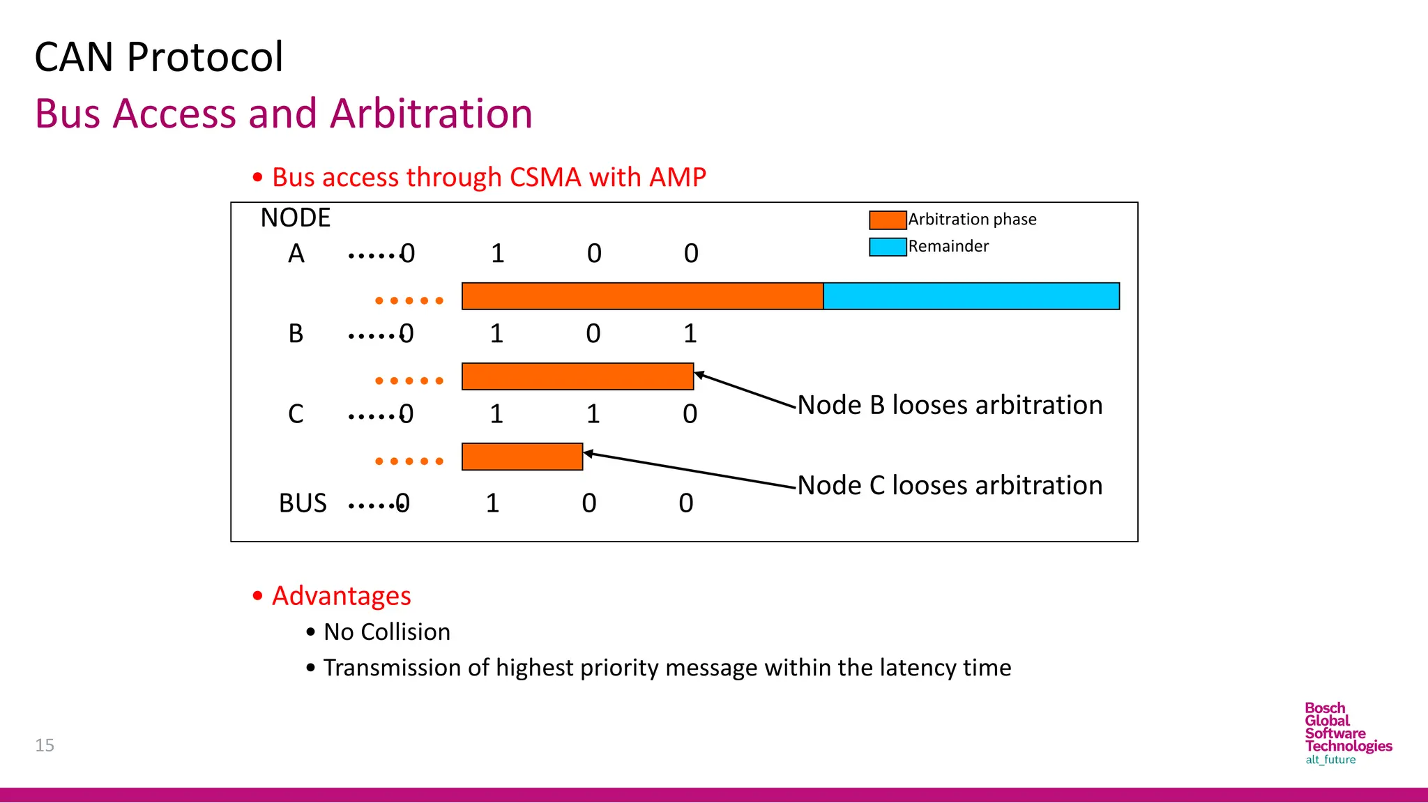
Bus Accessand Arbitration
• Bus access through CSMA with AMP
A 0 1 0 0
B 0 1 0 1
C 0 1 1 0
BUS 0 1 0 0
NODE
Node B looses arbitration
Node C looses arbitration
Arbitration phase
Remainder
• Advantages
• No Collision
• Transmission of highest priority message within the latency time
16.
CAN Protocol
16
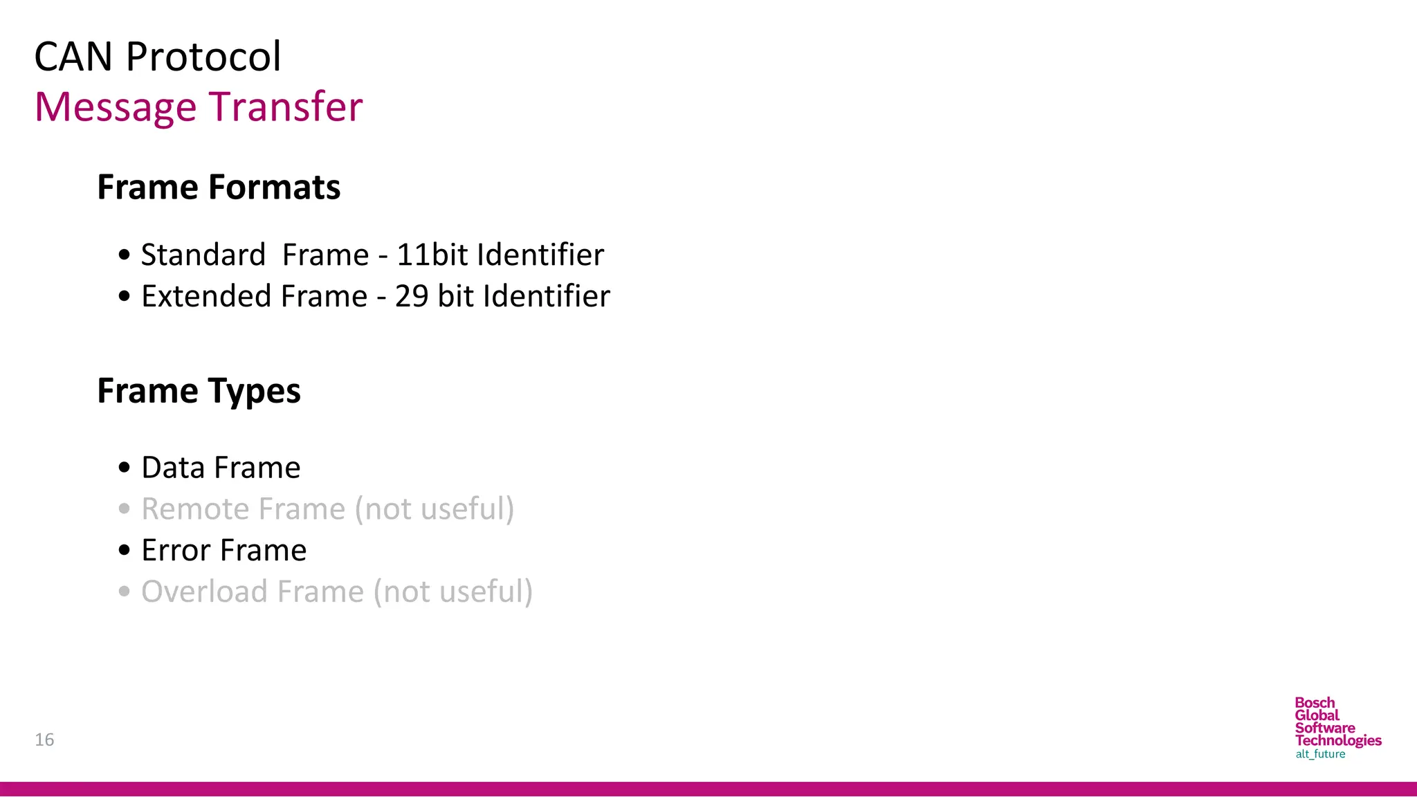
Message Transfer
FrameFormats
• Standard Frame - 11bit Identifier
• Extended Frame - 29 bit Identifier
Frame Types
• Data Frame
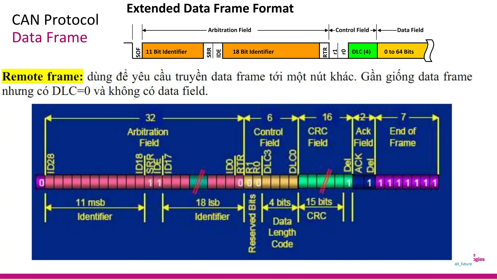
• Remote Frame (not useful)
• Error Frame
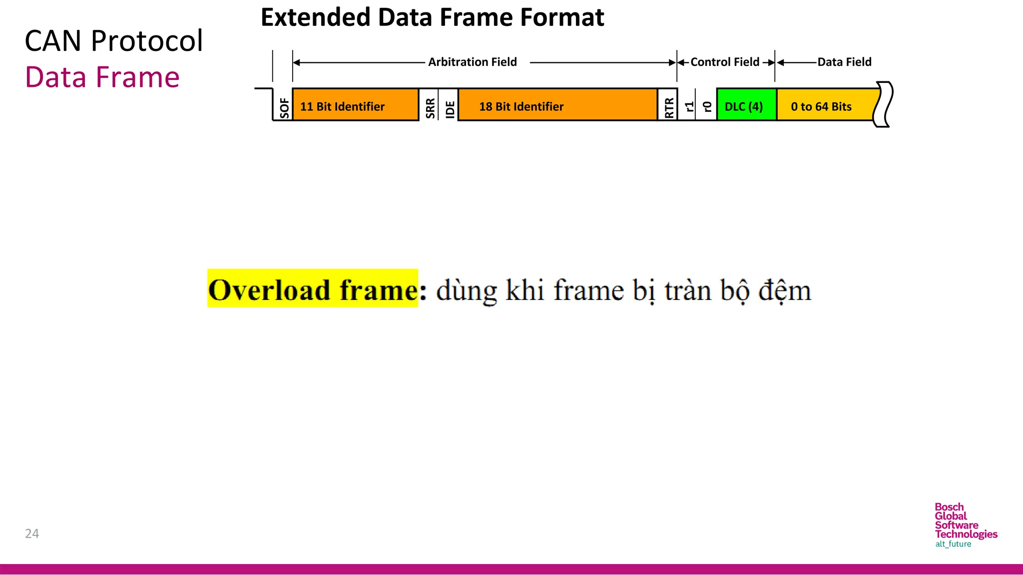
• Overload Frame (not useful)
17.
CAN Protocol
17
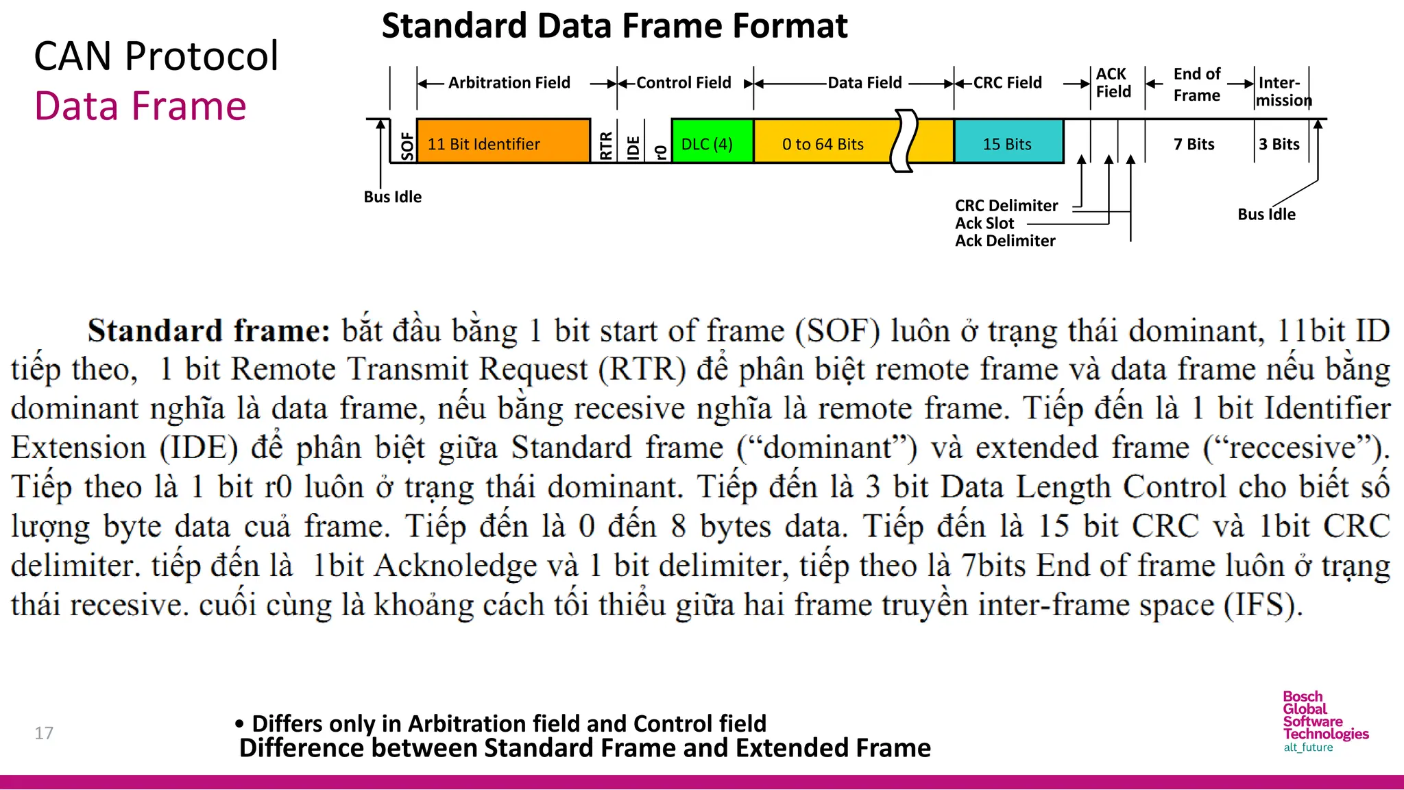
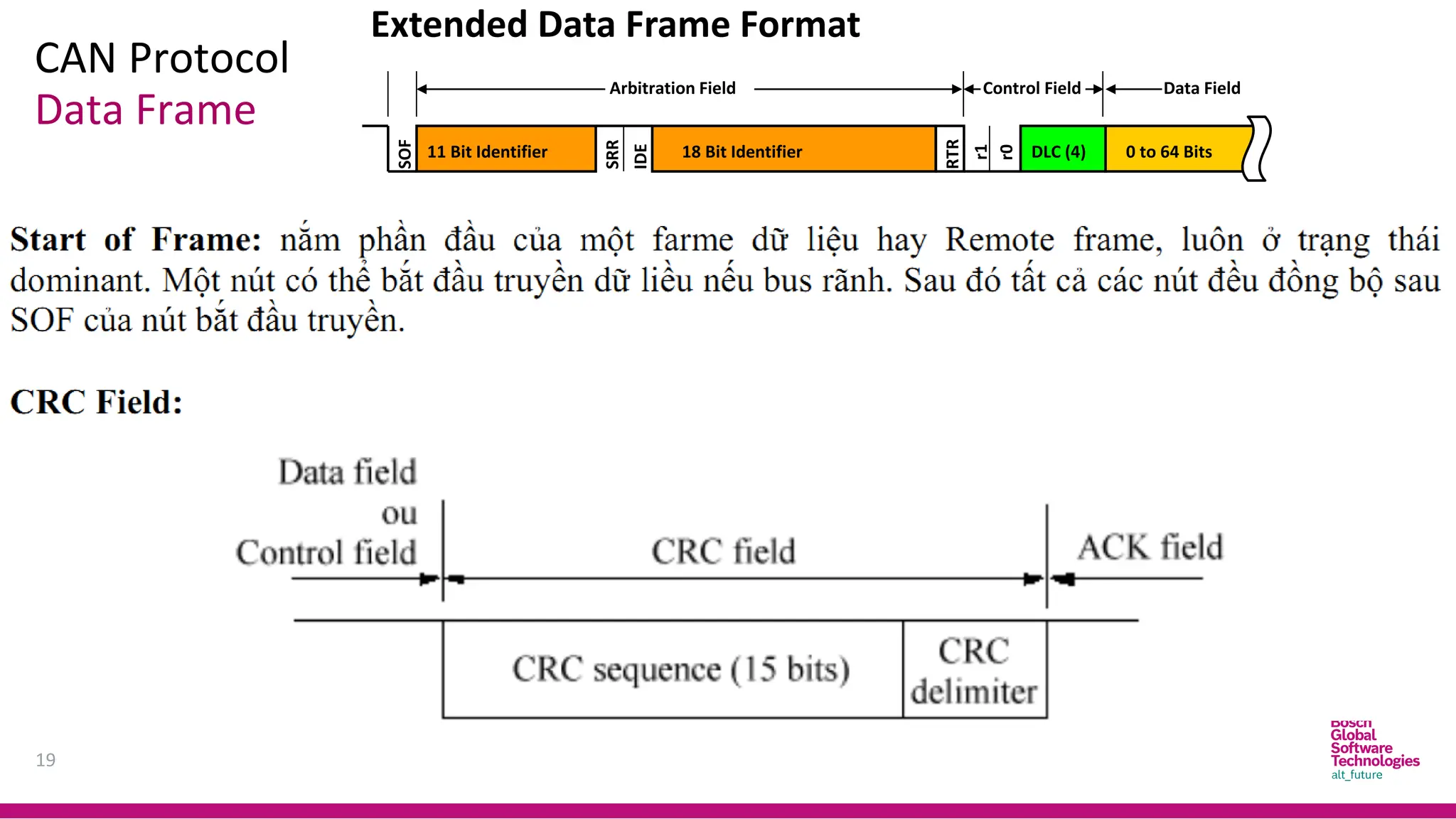
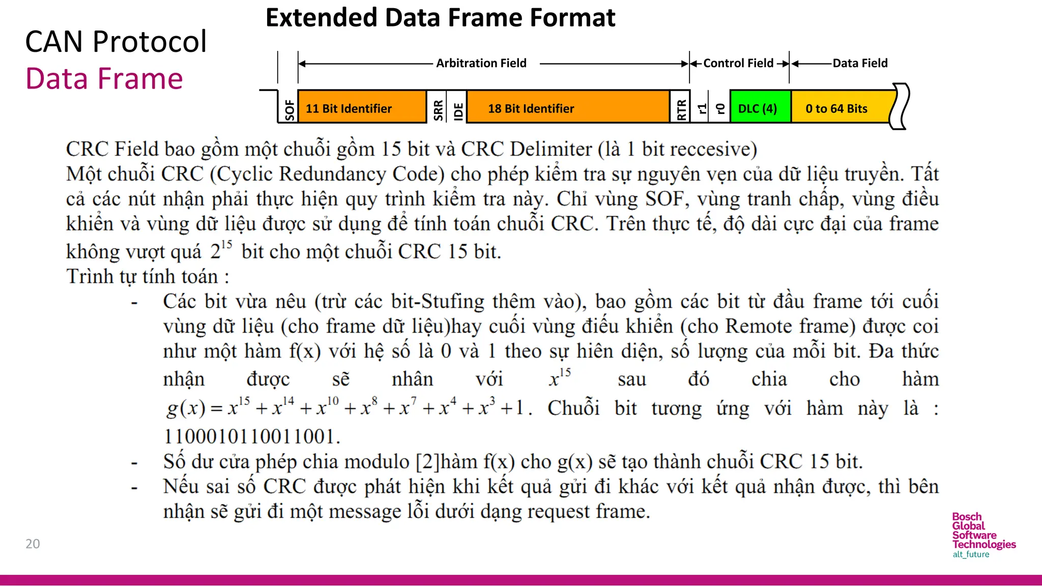
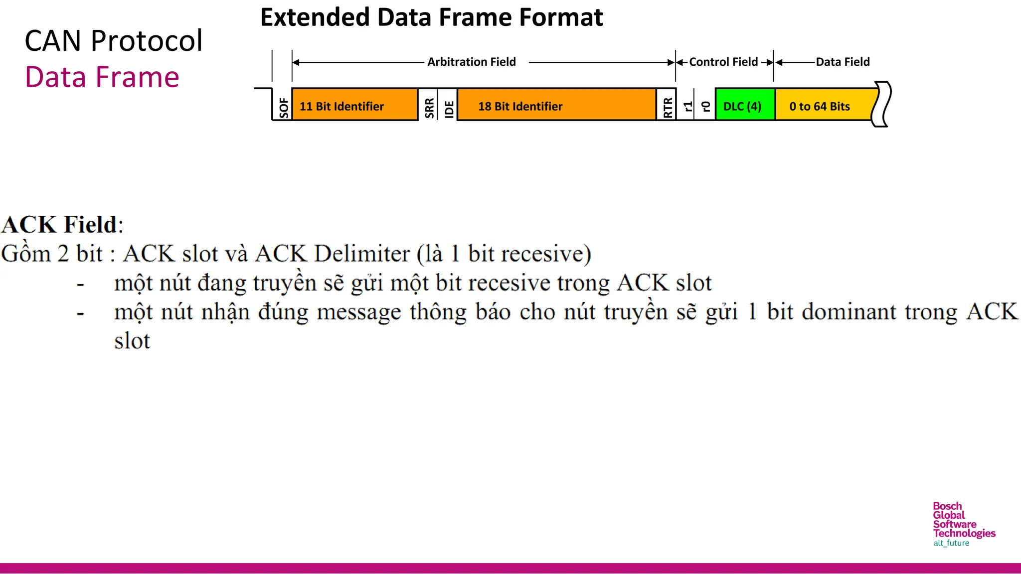
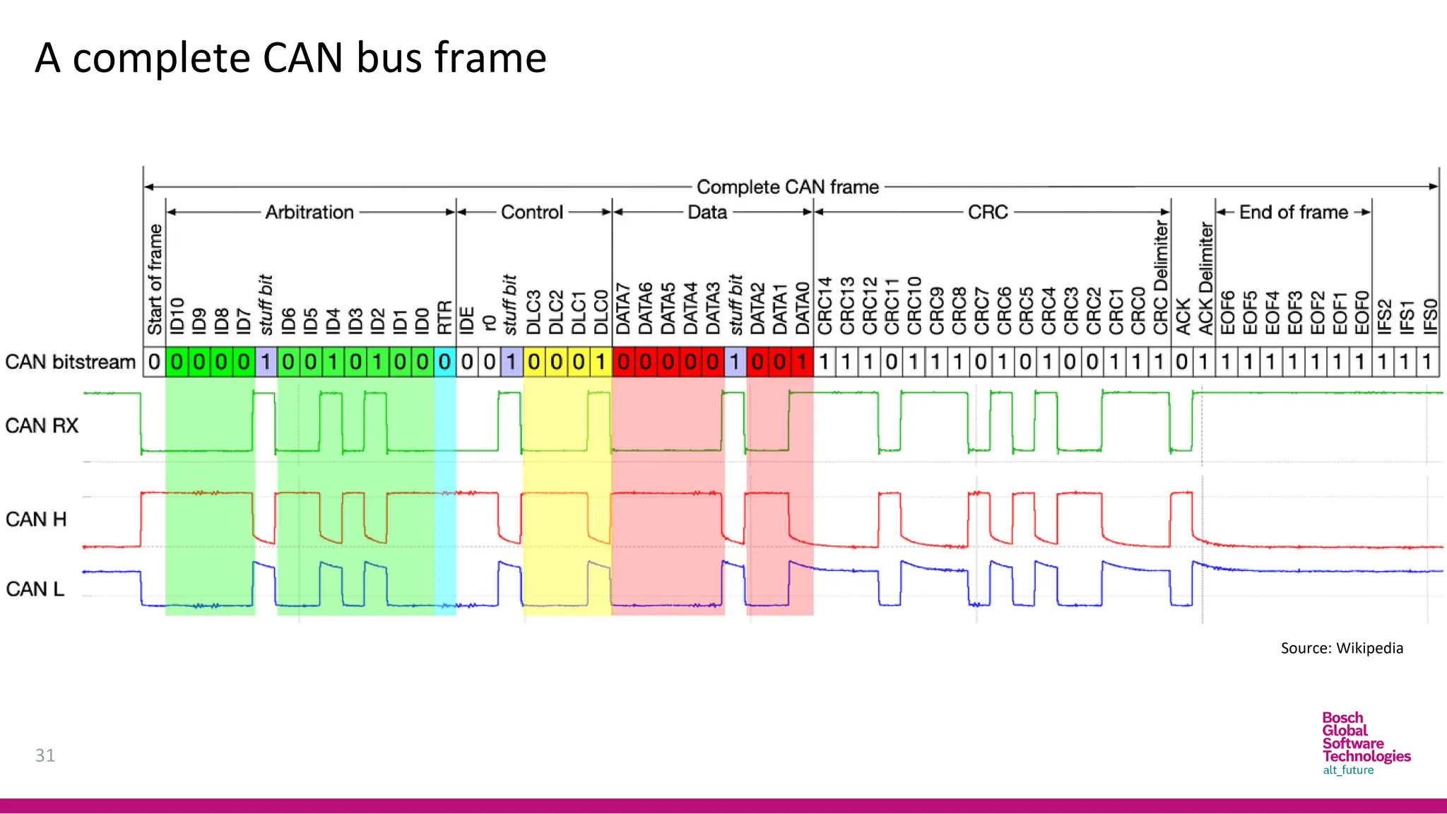
Data Frame
ControlField
SOF
RTR
11 Bit Identifier
Arbitration Field Data Field CRC Field
DLC (4)
IDE
r0
Field
ACK End of
Frame
0 to 64 Bits 15 Bits 7 Bits
Inter-
mission
Difference between Standard Frame and Extended Frame
• Differs only in Arbitration field and Control field
3 Bits
Bus Idle
Bus Idle
Ack Slot
CRC Delimiter
Ack Delimiter
Standard Data Frame Format
18.
CAN Protocol
18
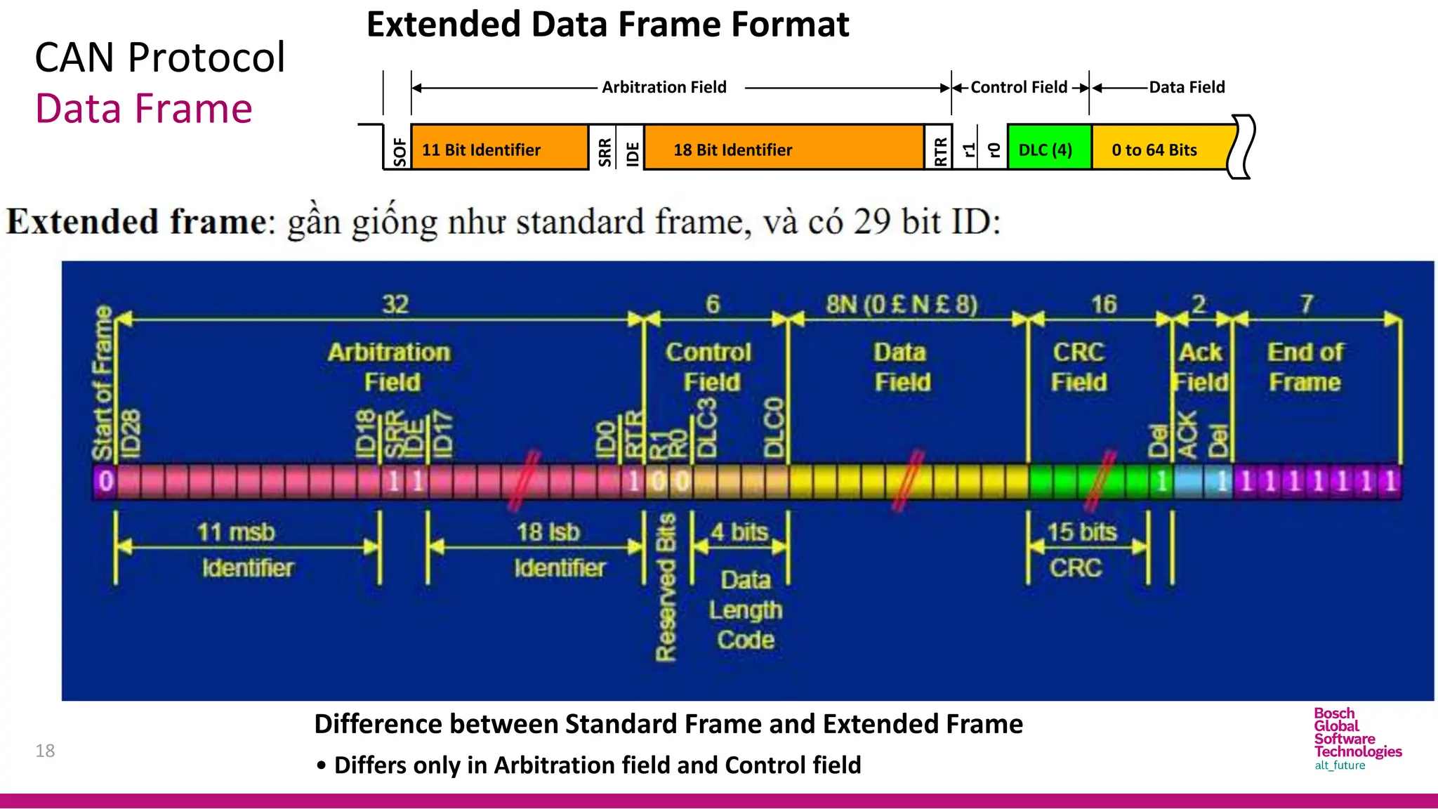
Data Frame
ExtendedData Frame Format
SOF
SRR
11 Bit Identifier
Arbitration Field
18 Bit Identifier
Control Field
RTR
Data Field
DLC (4)
IDE
r1
r0
0 to 64 Bits
Difference between Standard Frame and Extended Frame
• Differs only in Arbitration field and Control field
19.
CAN Protocol
19
Data Frame
ExtendedData Frame Format
SOF
SRR
11 Bit Identifier
Arbitration Field
18 Bit Identifier
Control Field
RTR
Data Field
DLC (4)
IDE
r1
r0
0 to 64 Bits
20.
CAN Protocol
20
Data Frame
ExtendedData Frame Format
SOF
SRR
11 Bit Identifier
Arbitration Field
18 Bit Identifier
Control Field
RTR
Data Field
DLC (4)
IDE
r1
r0
0 to 64 Bits
21.
CAN Protocol
Data Frame
ExtendedData Frame Format
SOF
SRR
11 Bit Identifier
Arbitration Field
18 Bit Identifier
Control Field
RTR
Data Field
DLC (4)
IDE
r1
r0
0 to 64 Bits
22.
CAN Protocol
Data Frame
ExtendedData Frame Format
SOF
SRR
11 Bit Identifier
Arbitration Field
18 Bit Identifier
Control Field
RTR
Data Field
DLC (4)
IDE
r1
r0
0 to 64 Bits
23.
CAN Protocol
23
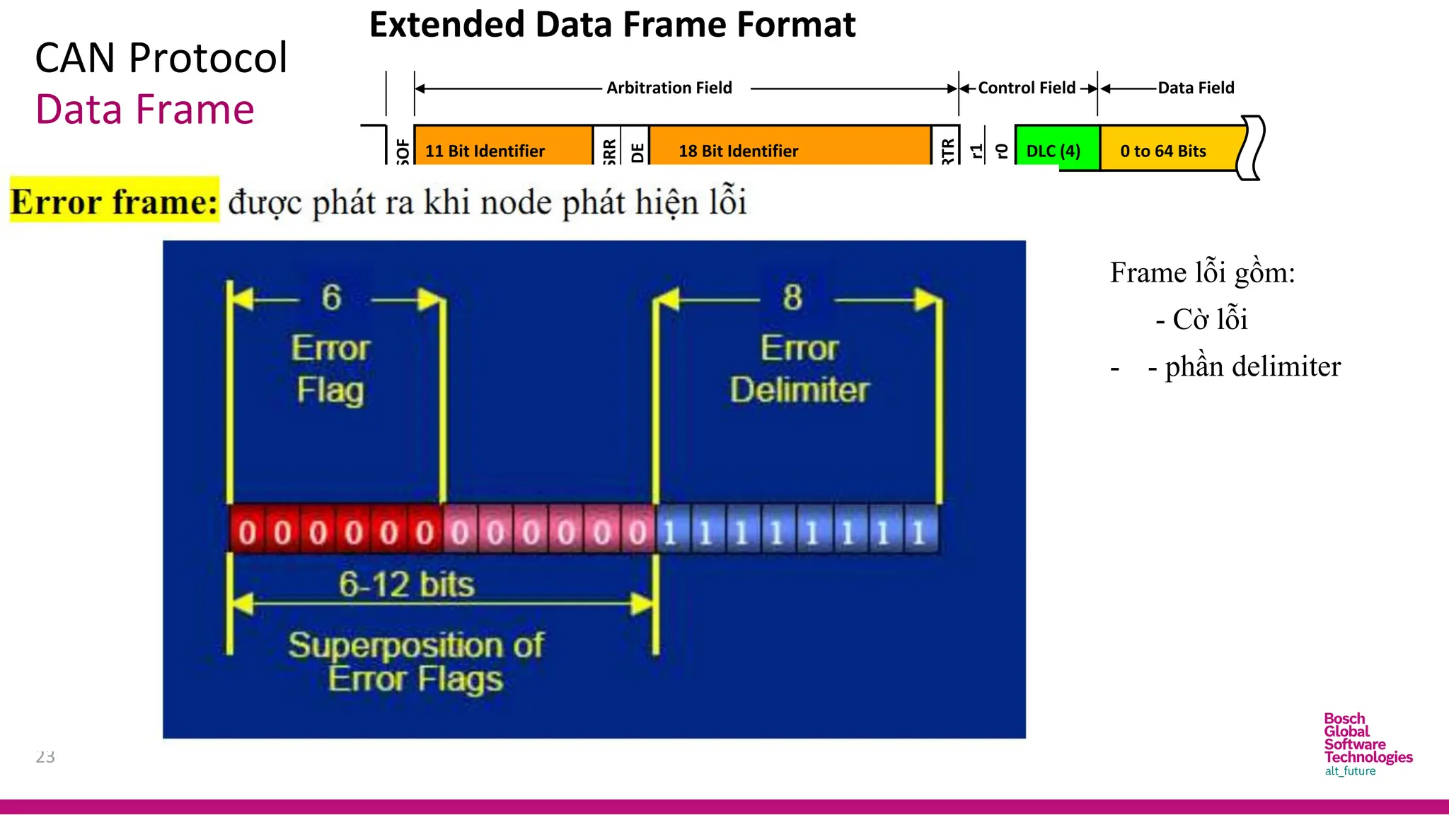
Data Frame
ExtendedData Frame Format
SOF
SRR
11 Bit Identifier
Arbitration Field
18 Bit Identifier
Control Field
RTR
Data Field
DLC (4)
IDE
r1
r0
0 to 64 Bits
Frame lỗi gồm:
- Cờ lỗi
- - phần delimiter
24.
CAN Protocol
24
Data Frame
ExtendedData Frame Format
SOF
SRR
11 Bit Identifier
Arbitration Field
18 Bit Identifier
Control Field
RTR
Data Field
DLC (4)
IDE
r1
r0
0 to 64 Bits
25.
CAN Protocol
25
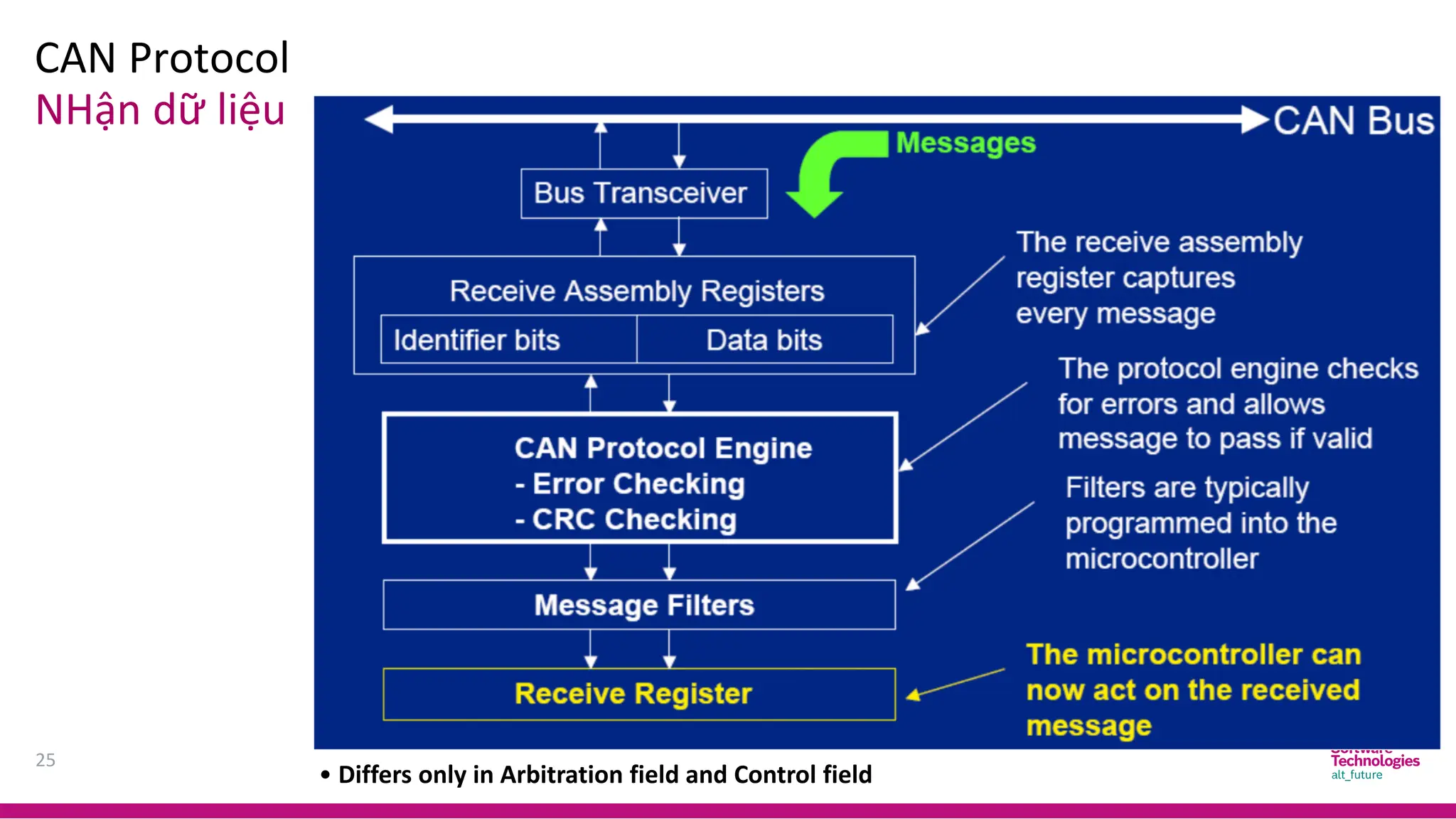
NHận dữliệu
Difference between Standard Frame and Extended Frame
• Differs only in Arbitration field and Control field
CAN Protocol
27
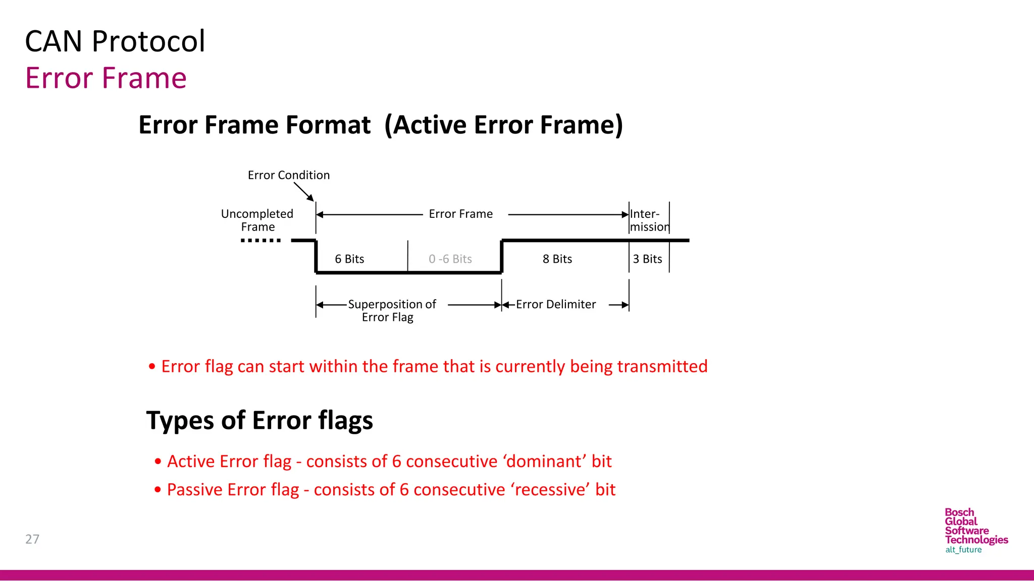
Error Frame
ErrorFrame
Frame
Uncompleted Inter-
mission
6 Bits 0 -6 Bits 8 Bits
Error Delimiter
Superposition of
Error Flag
Error Condition
3 Bits
• Error flag can start within the frame that is currently being transmitted
Types of Error flags
• Active Error flag - consists of 6 consecutive ‘dominant’ bit
• Passive Error flag - consists of 6 consecutive ‘recessive’ bit
Error Frame Format (Active Error Frame)
28.
CAN Protocol
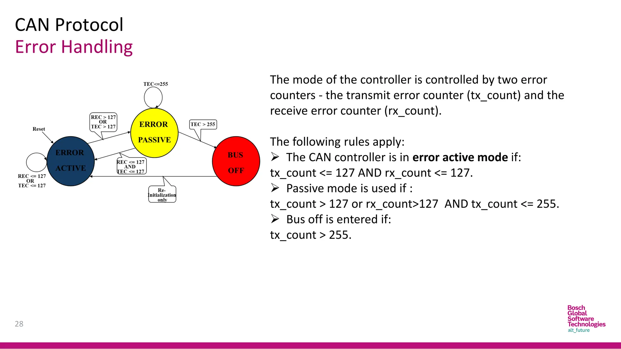
Error Handling
28
Themode of the controller is controlled by two error
counters - the transmit error counter (tx_count) and the
receive error counter (rx_count).
The following rules apply:
➢ The CAN controller is in error active mode if:
tx_count <= 127 AND rx_count <= 127.
➢ Passive mode is used if :
tx_count > 127 or rx_count>127 AND tx_count <= 255.
➢ Bus off is entered if:
tx_count > 255.
29.
CAN Protocol
29
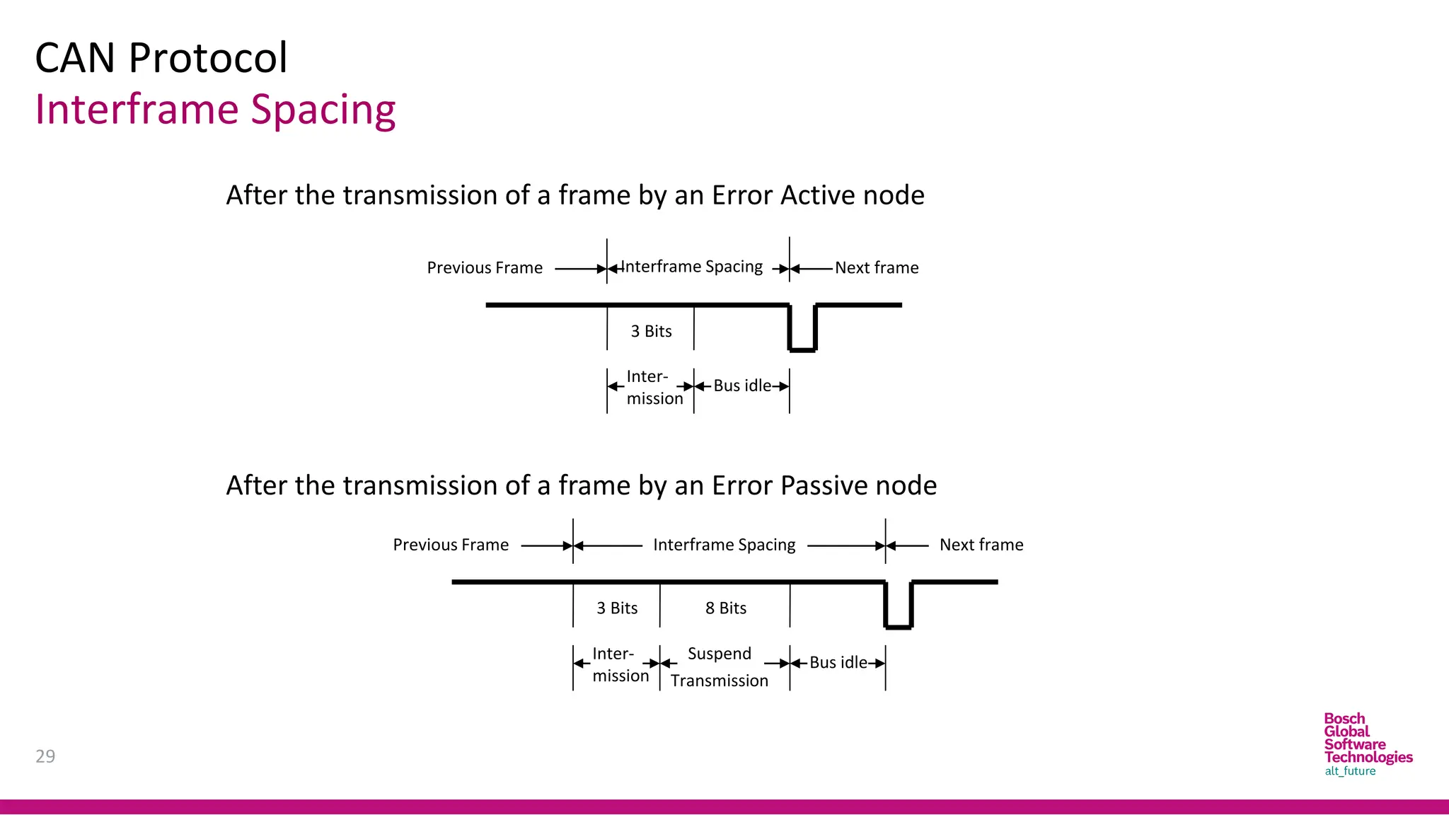
Interframe Spacing
8Bits
3 Bits
Previous Frame Interframe Spacing Next frame
Inter-
mission
Bus idle
3 Bits
Previous Frame Interframe Spacing Next frame
Inter-
mission
Bus idle
Transmission
Suspend
After the transmission of a frame by an Error Active node
After the transmission of a frame by an Error Passive node
30.
30
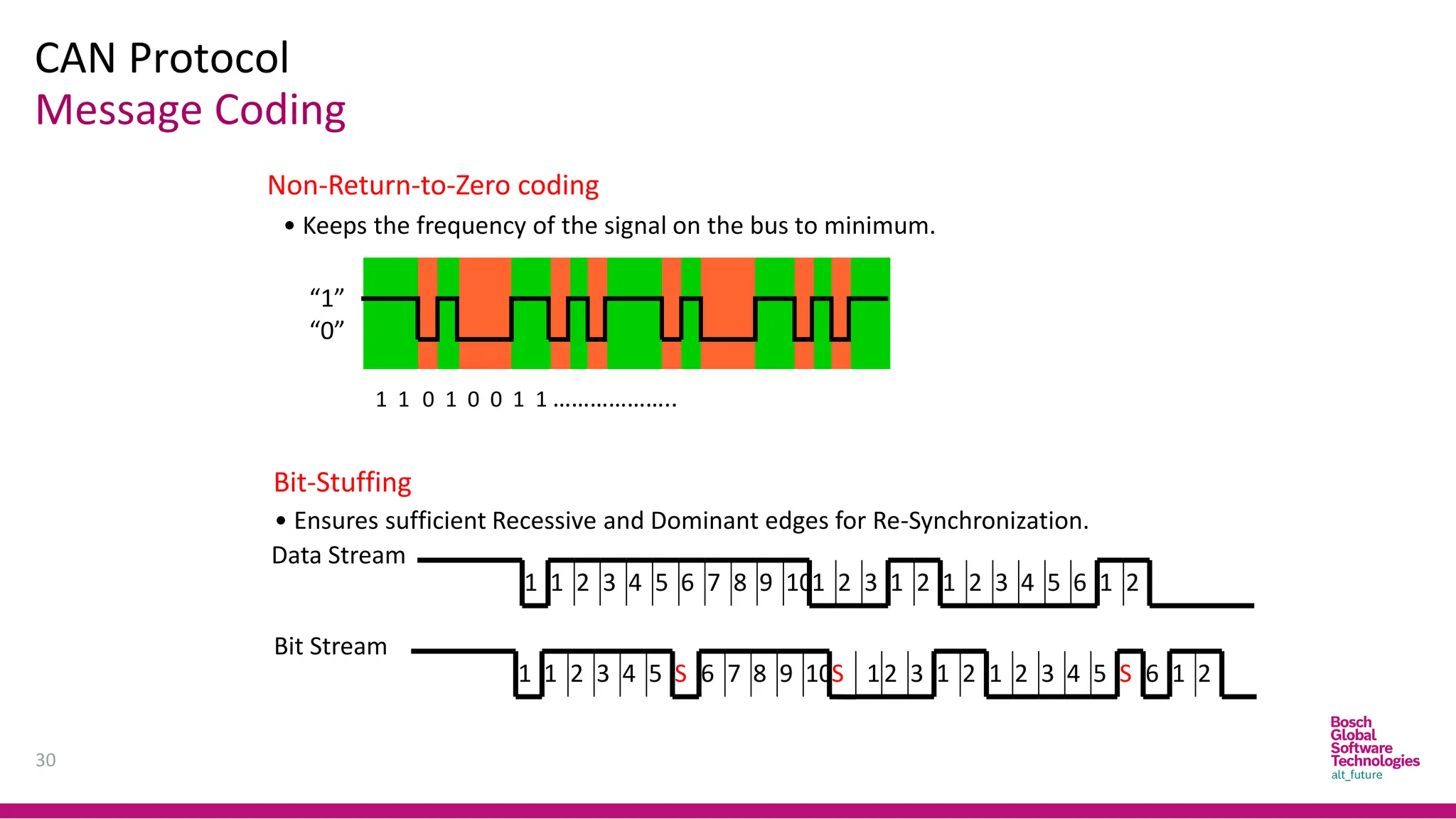
1 1 01 0 0 1 1 ………………..
“1”
“0”
Non-Return-to-Zero coding
• Keeps the frequency of the signal on the bus to minimum.
Bit-Stuffing
• Ensures sufficient Recessive and Dominant edges for Re-Synchronization.
7 10
9
8 1 2 3 1 2 1 2 3 5
4 6 1 2
Data Stream
1 2 3 5
4 6
1
1 2 3 5
4
1 7 9
8
6
S 10S 12 3 1 2 1 2 3 5
4 6
S 1 2
Bit Stream
CAN Protocol
Message Coding
CAN Protocol
32
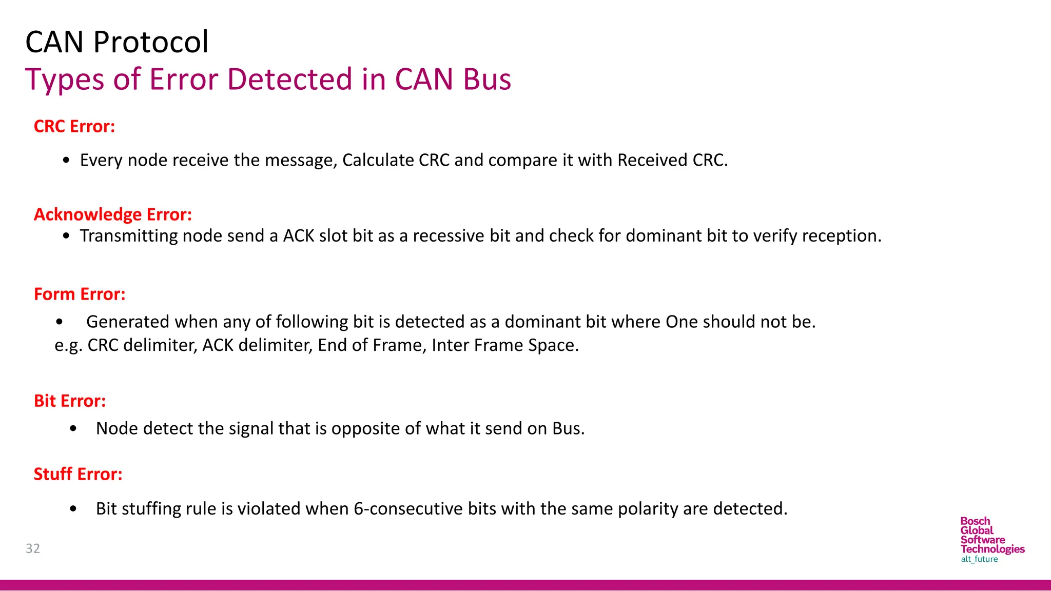
Types ofError Detected in CAN Bus
CRC Error:
• Every node receive the message, Calculate CRC and compare it with Received CRC.
Acknowledge Error:
• Transmitting node send a ACK slot bit as a recessive bit and check for dominant bit to verify reception.
Form Error:
• Generated when any of following bit is detected as a dominant bit where One should not be.
e.g. CRC delimiter, ACK delimiter, End of Frame, Inter Frame Space.
Stuff Error:
• Bit stuffing rule is violated when 6-consecutive bits with the same polarity are detected.
Bit Error:
• Node detect the signal that is opposite of what it send on Bus.
33.
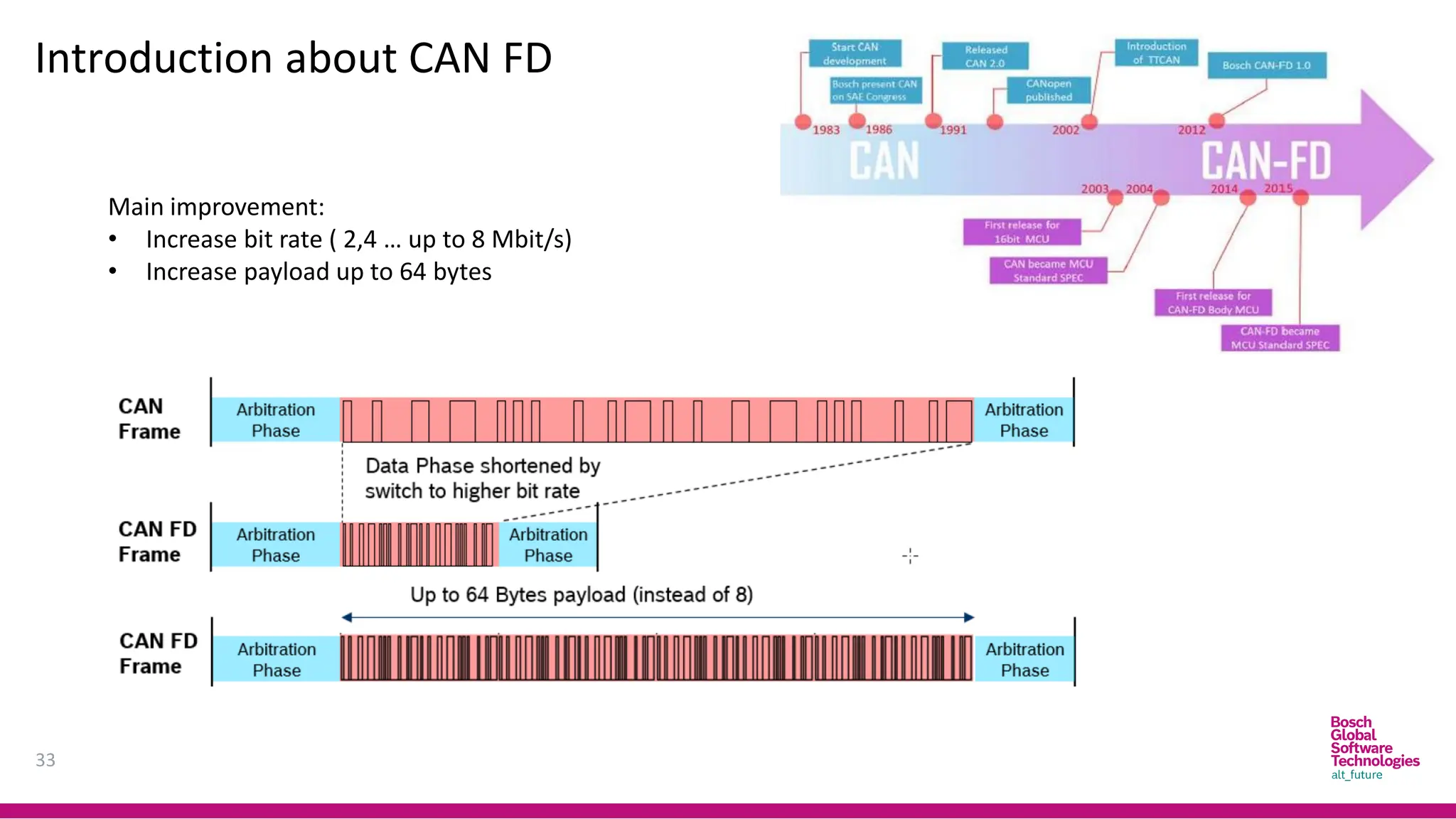
Introduction about CANFD
33
Main improvement:
• Increase bit rate ( 2,4 … up to 8 Mbit/s)
• Increase payload up to 64 bytes
34.
34
Abbreviation
CAN: Controller AreaNetwork
CAN FD: Controller Area Network Flexible Data-Rate
CSMA: Carrier Sense Multiple Access/ Collision Detection
AMP: Arbitration on Message Priority
OSI: Open Systems Interconnection model
SOF: Start Of Frame
RTR bit: Remote Transmission Request bit
SRR bit: Substitute Remote Request bit
IDE bit: Identifier Extension
DLC: Data Length Code
EOF: End Of Frame
CRC: Cyclic Redundancy Check/ Check sum
ACK bit: Acknowledgment bit
IFS: Inter Frame Space
REC: Receive Error Counter
TEC: Transmit Error Counter
35.
35
Reference
- CAN Specification2.0 – Bosch
- ISO 11898-2 – High speed CAN
- ISO 11898-2 2015 – CAN FD
- Bit timing calculation: http://www.bittiming.can-wiki.info/
- Return to zero: https://en.wikipedia.org/wiki/Return-to-zero
- None return to zero : https://en.wikipedia.org/wiki/Non-return-to-zero
- CSMA/CD : https://en.wikipedia.org/wiki/Carrier-sense_multiple_access_with_collision_detection
Trainer Introduction
37
NGUYEN KIEN
SWArchitect – RADAR product
9 years experience in Bosch DA/RADAR development
Bachelor of Engineering – Embedded System
38.
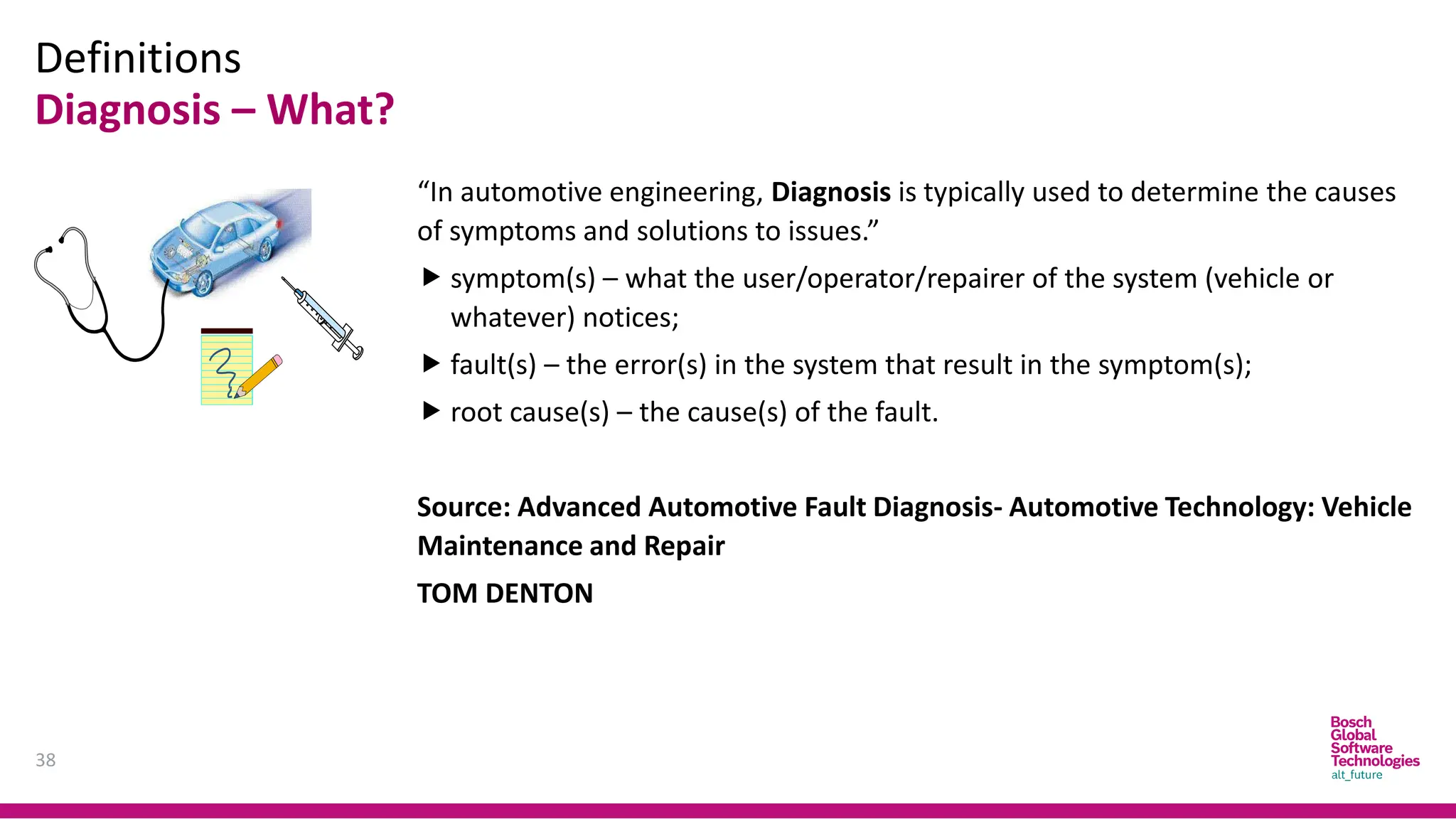
Definitions
Diagnosis – What?
38
“Inautomotive engineering, Diagnosis is typically used to determine the causes
of symptoms and solutions to issues.”
symptom(s) – what the user/operator/repairer of the system (vehicle or
whatever) notices;
fault(s) – the error(s) in the system that result in the symptom(s);
root cause(s) – the cause(s) of the fault.
Source: Advanced Automotive Fault Diagnosis- Automotive Technology: Vehicle
Maintenance and Repair
TOM DENTON
39.
Definitions
Diagnosis – How?[1]
39
Todo Diagnostic, Technician have to know how to use Diagnostic Tools and
Equipment.
Tool and Equipment could be classified into:
Basic Equipment: such as Multi-meter
Tracing Tool: like Oscilloscope
Scanner/Fault Code Readers and Analyzers.
40.
Definitions
Diagnosis – How?[2]
40
The Equipment shall help technician indicate where is fault occurs in systems.
In the other word, In Vehicle, Systems should have ability to provide
information in case request.
This is the motivation of On-board diagnostics (OBD).
On-board diagnostics (OBD) is a generic term referring to a vehicle’s self-
diagnostic and reporting system. OBD systems give the vehicle owner or a
technician access to information for various vehicle systems.
OBD system illuminates a warning lamp known as the malfunction indicator
lamp (MIL) or malfunction indicator (MI) on the instrument cluster.
41.
Definitions
Diagnosis – How?[3]
41
When the fault occurs, the system stores a diagnostic trouble code (DTC), also
store important information of the vehicle when the fault was set.
A service technician is able to connect a diagnostic scan tool or a code reader
that will communicate with the system and retrieve this information.
As vehicles and their systems become more complex, the functionality of OBD
is being extended to cover vehicle systems and components that do not have
anything to do with vehicle emissions control: Vehicle body, chassis and
accessories
OBD systems use a standardized communications port to provide data
The Communication between Diagnostic Equipment and ECUs through Vehicle
Special Interface for Diagnosis purpose is called Diagnostic Communication.
42.
Definitions
States and Events
42
Everything about the car is either in a "normal" state or an "abnormal" state.
Either the car is starting normally or it is not. Either the engine is running
normally or it is not.
Used in this way, "normal" means acceptable, the way they are supposed to
be, okay. "Abnormal" means not acceptable, not the way they are supposed to
be, not okay.
The purpose of all automobile repair is to correct abnormal states and restore
the car to its normal state of operation.
43.
Definitions
States and Events
43
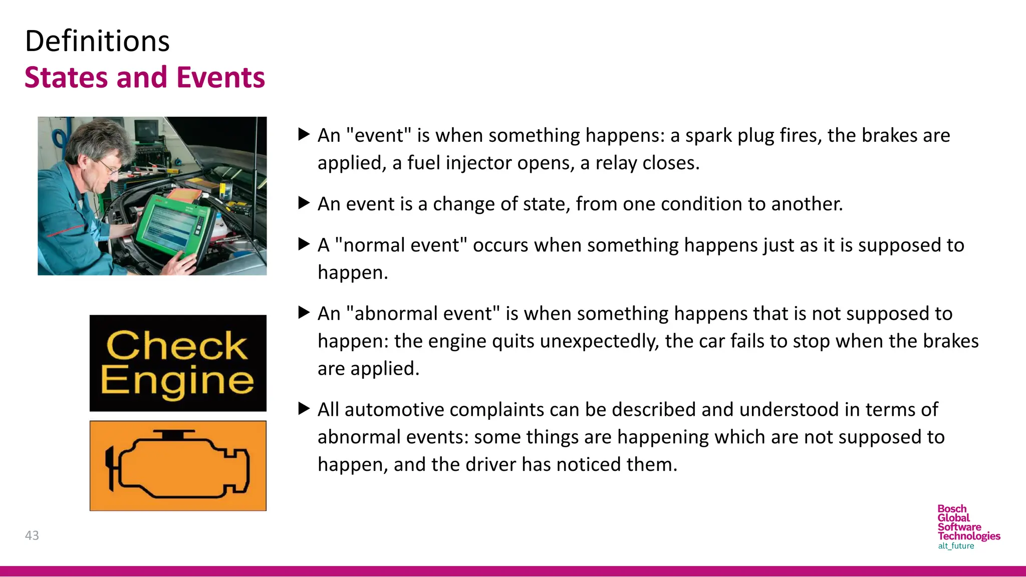
An "event" is when something happens: a spark plug fires, the brakes are
applied, a fuel injector opens, a relay closes.
An event is a change of state, from one condition to another.
A "normal event" occurs when something happens just as it is supposed to
happen.
An "abnormal event" is when something happens that is not supposed to
happen: the engine quits unexpectedly, the car fails to stop when the brakes
are applied.
All automotive complaints can be described and understood in terms of
abnormal events: some things are happening which are not supposed to
happen, and the driver has noticed them.
44.
Diagnosis Uses
44
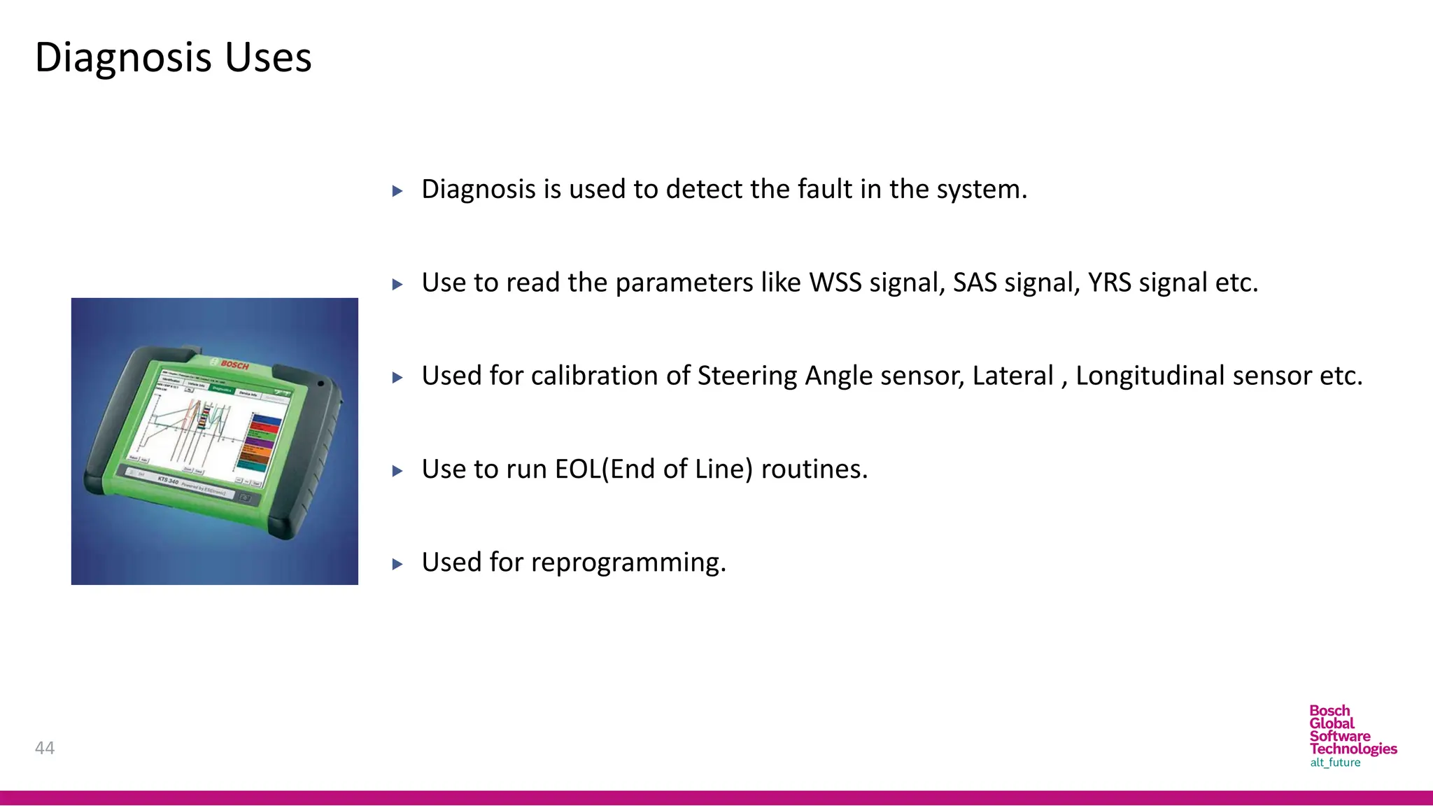
Diagnosisis used to detect the fault in the system.
Use to read the parameters like WSS signal, SAS signal, YRS signal etc.
Used for calibration of Steering Angle sensor, Lateral , Longitudinal sensor etc.
Use to run EOL(End of Line) routines.
Used for reprogramming.
45.
On board andOff board Diagnosis
45
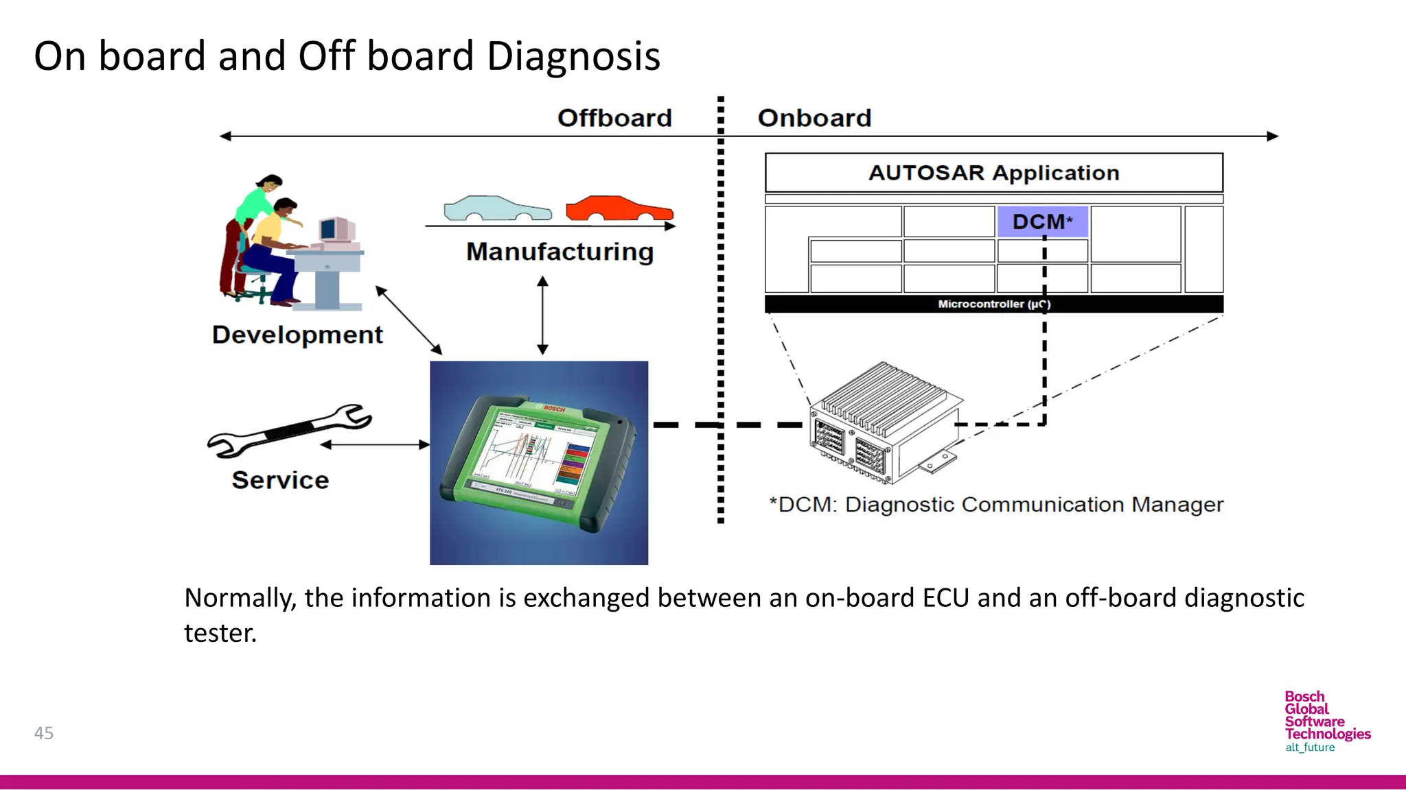
Normally, the information is exchanged between an on-board ECU and an off-board diagnostic
tester.
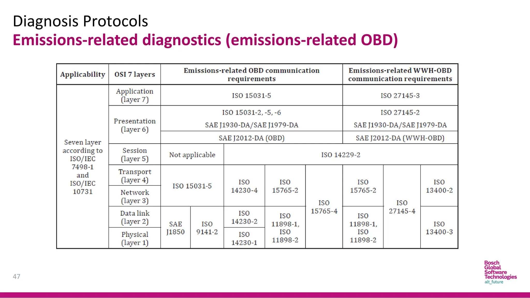
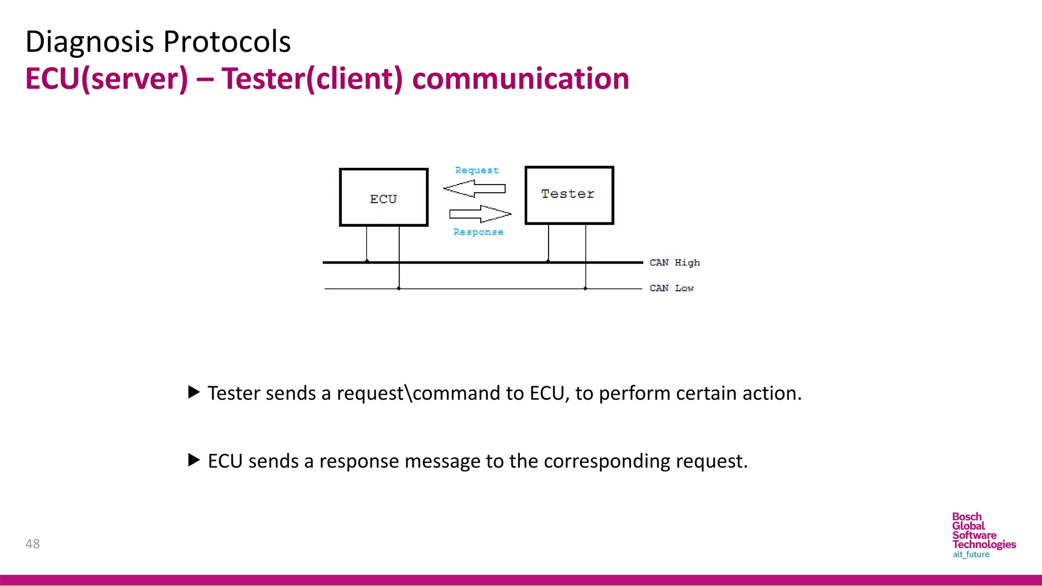
Diagnosis Protocols
48
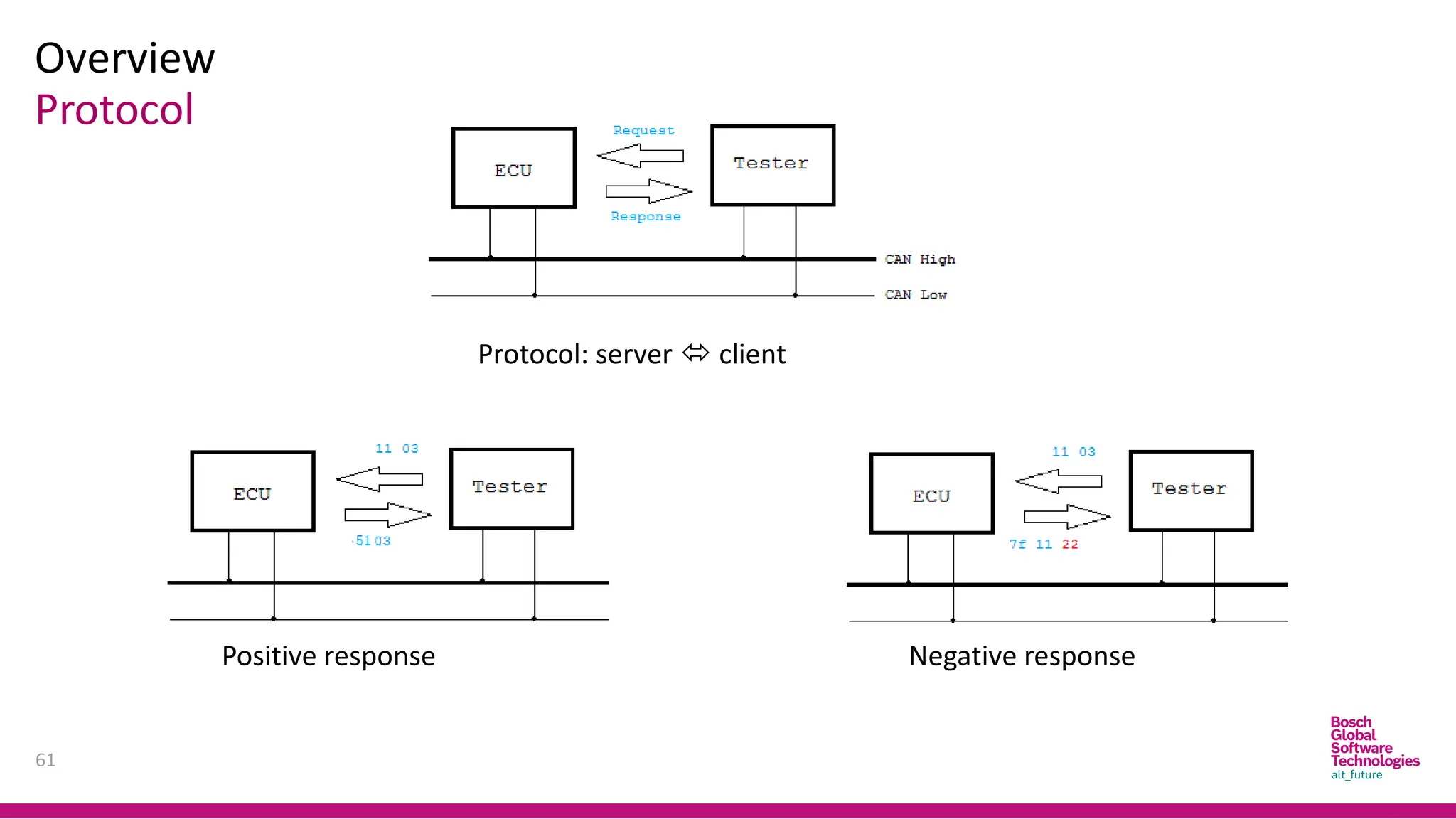
ECU(server) –Tester(client) communication
Tester sends a requestcommand to ECU, to perform certain action.
ECU sends a response message to the corresponding request.
49.
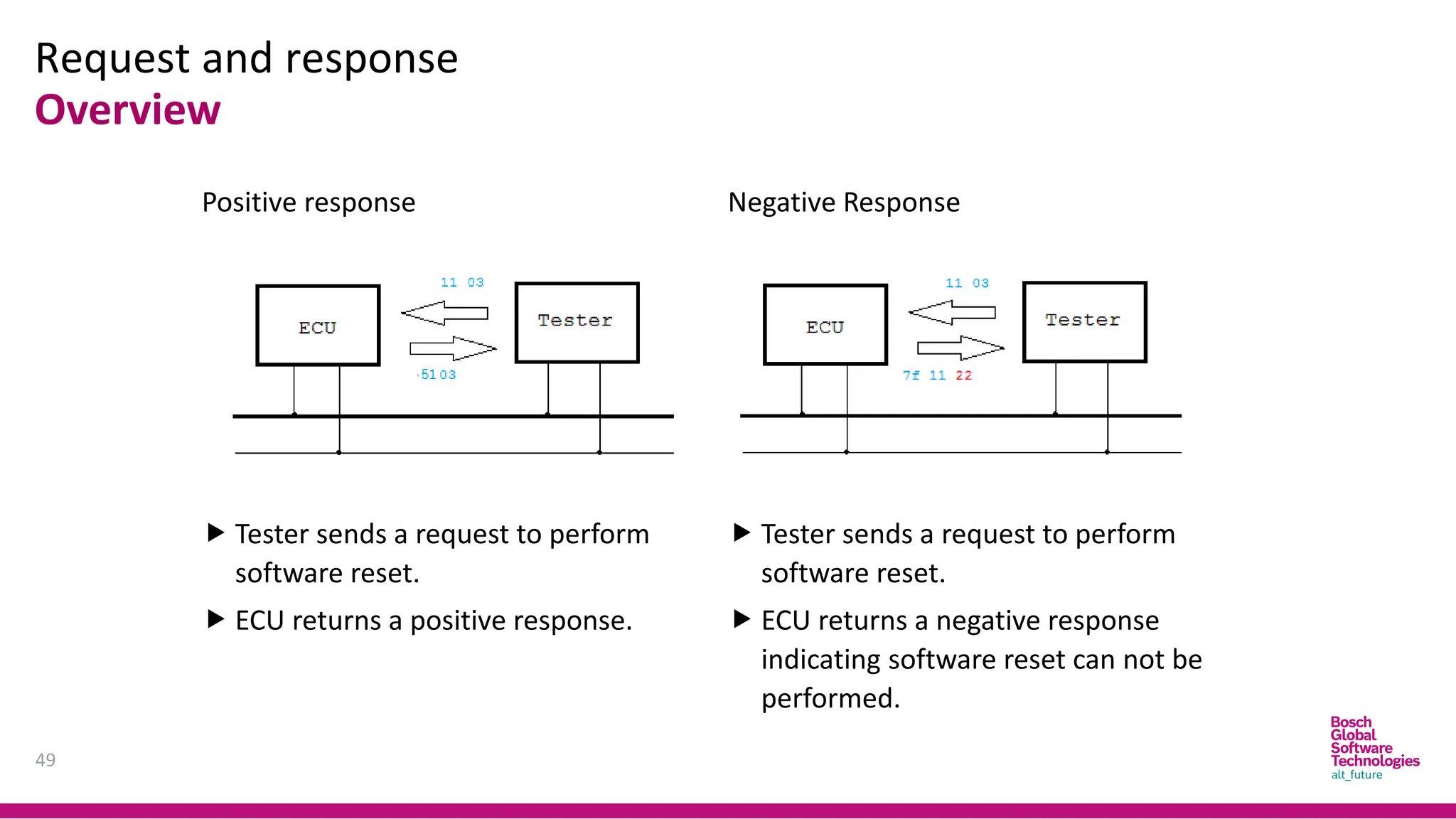
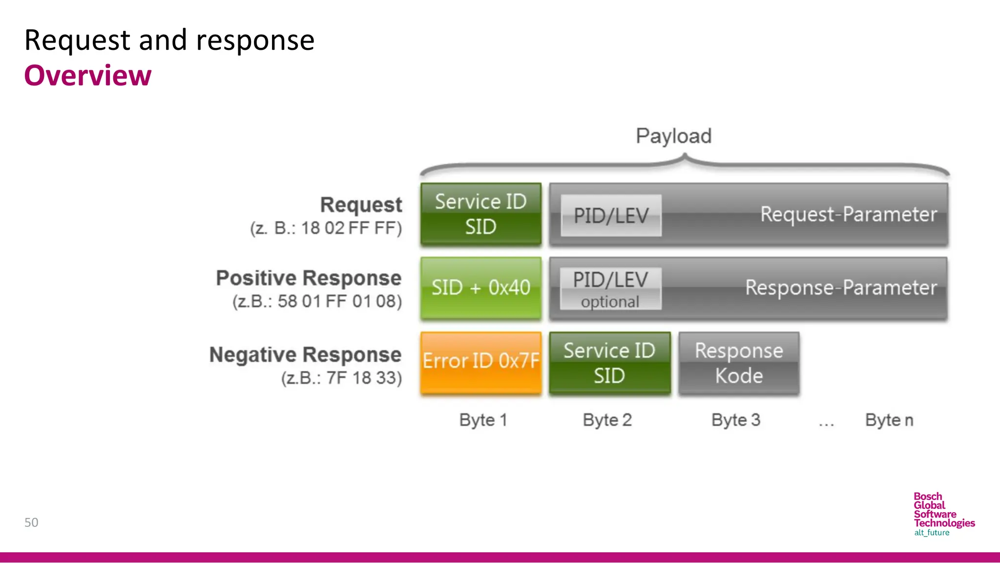
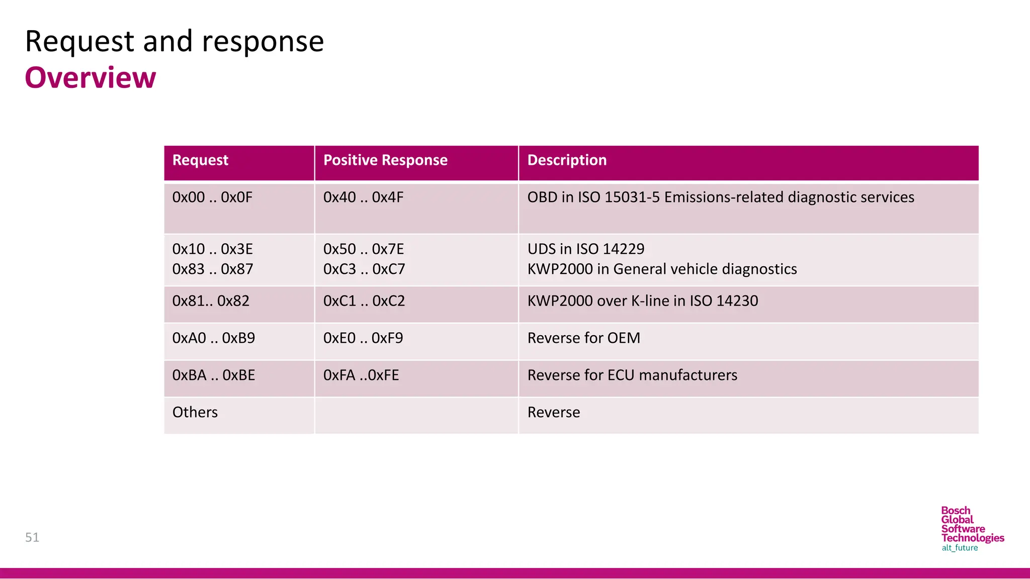
Request and response
49
Overview
Positiveresponse
Tester sends a request to perform
software reset.
ECU returns a positive response.
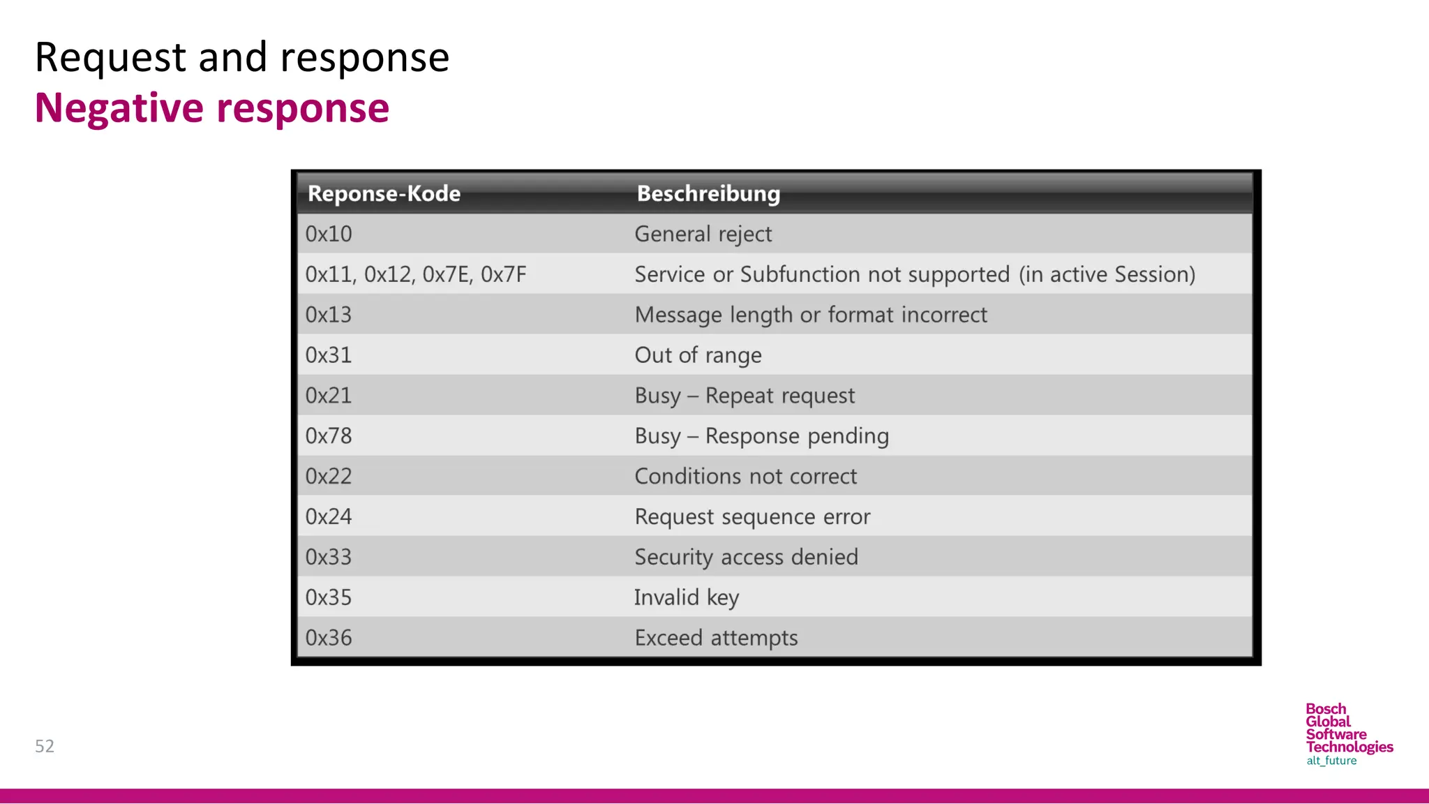
Negative Response
Tester sends a request to perform
software reset.
ECU returns a negative response
indicating software reset can not be
performed.
Definitions
Milestones
55
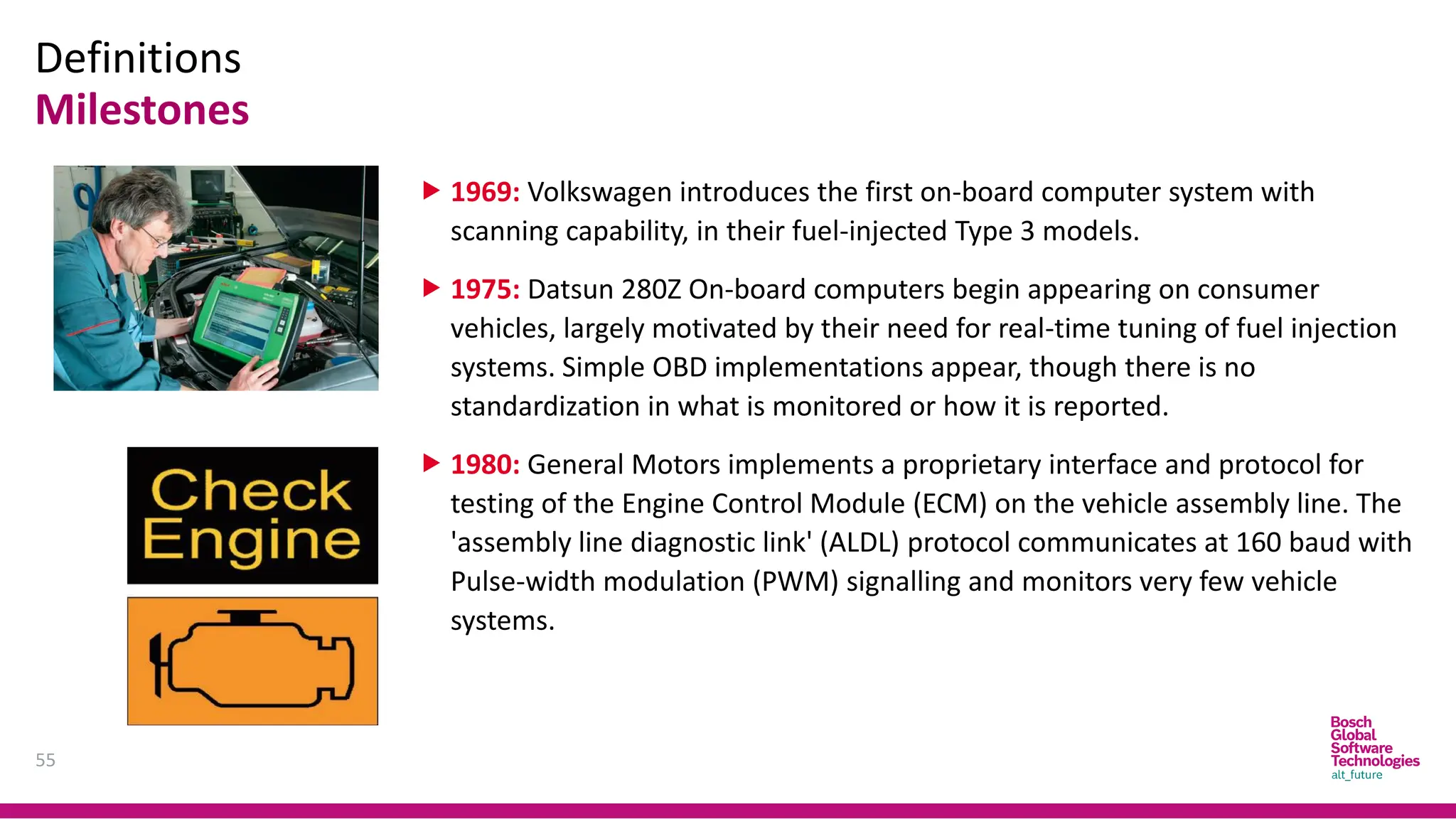
1969: Volkswagenintroduces the first on-board computer system with
scanning capability, in their fuel-injected Type 3 models.
1975: Datsun 280Z On-board computers begin appearing on consumer
vehicles, largely motivated by their need for real-time tuning of fuel injection
systems. Simple OBD implementations appear, though there is no
standardization in what is monitored or how it is reported.
1980: General Motors implements a proprietary interface and protocol for
testing of the Engine Control Module (ECM) on the vehicle assembly line. The
'assembly line diagnostic link' (ALDL) protocol communicates at 160 baud with
Pulse-width modulation (PWM) signalling and monitors very few vehicle
systems.
56.
Definitions
Milestones
56
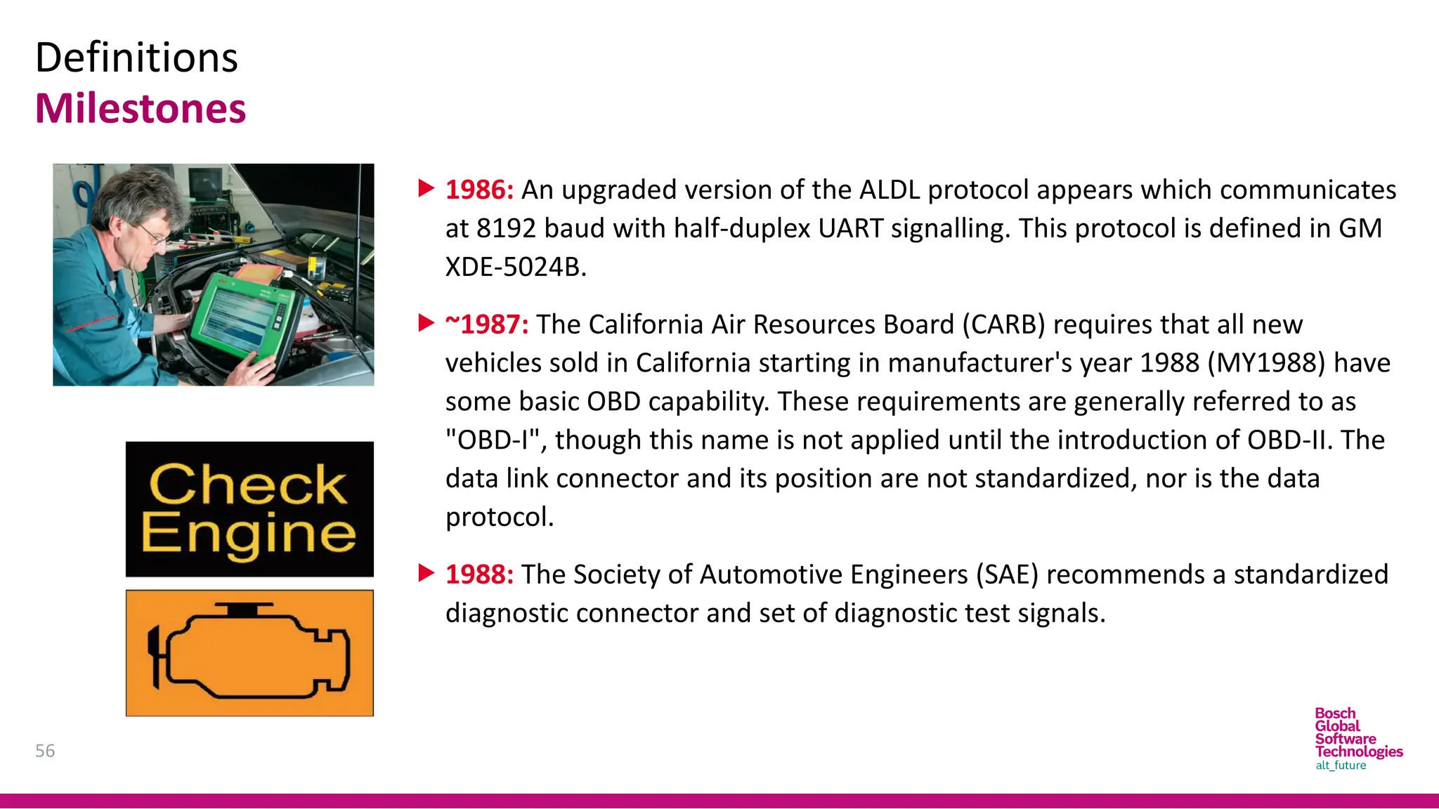
1986: Anupgraded version of the ALDL protocol appears which communicates
at 8192 baud with half-duplex UART signalling. This protocol is defined in GM
XDE-5024B.
~1987: The California Air Resources Board (CARB) requires that all new
vehicles sold in California starting in manufacturer's year 1988 (MY1988) have
some basic OBD capability. These requirements are generally referred to as
"OBD-I", though this name is not applied until the introduction of OBD-II. The
data link connector and its position are not standardized, nor is the data
protocol.
1988: The Society of Automotive Engineers (SAE) recommends a standardized
diagnostic connector and set of diagnostic test signals.
57.
Definitions
Milestones
57
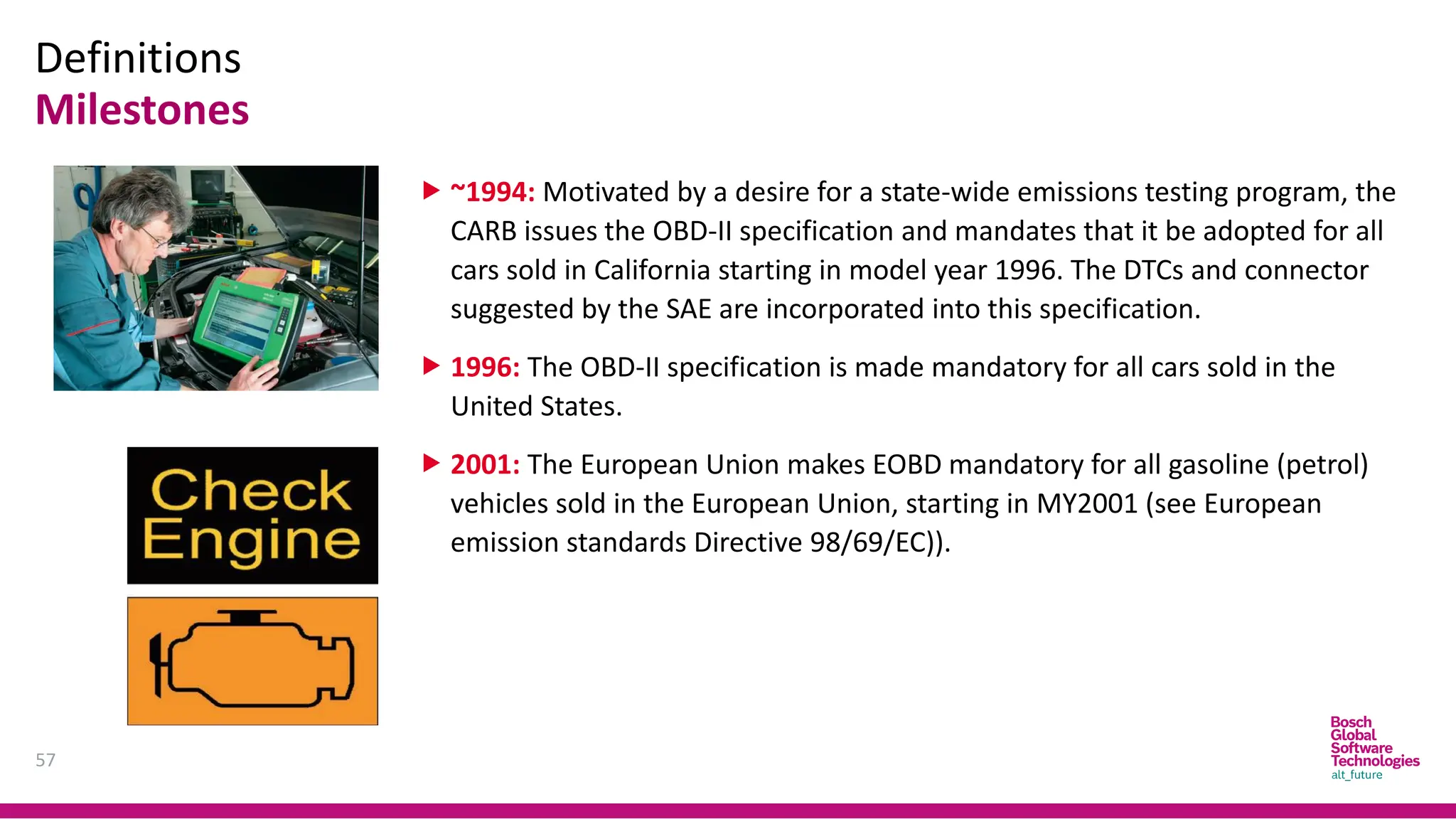
~1994: Motivatedby a desire for a state-wide emissions testing program, the
CARB issues the OBD-II specification and mandates that it be adopted for all
cars sold in California starting in model year 1996. The DTCs and connector
suggested by the SAE are incorporated into this specification.
1996: The OBD-II specification is made mandatory for all cars sold in the
United States.
2001: The European Union makes EOBD mandatory for all gasoline (petrol)
vehicles sold in the European Union, starting in MY2001 (see European
emission standards Directive 98/69/EC)).
Agenda
59
1. Overview
1. UDS
2.Diagnostic Communication Protocol
3. Related ISO Standards
2. UDS In General
1. Application Layer
2. Session Layer
3. UDS In CAN Implementation
60.
UDS
Overview
60
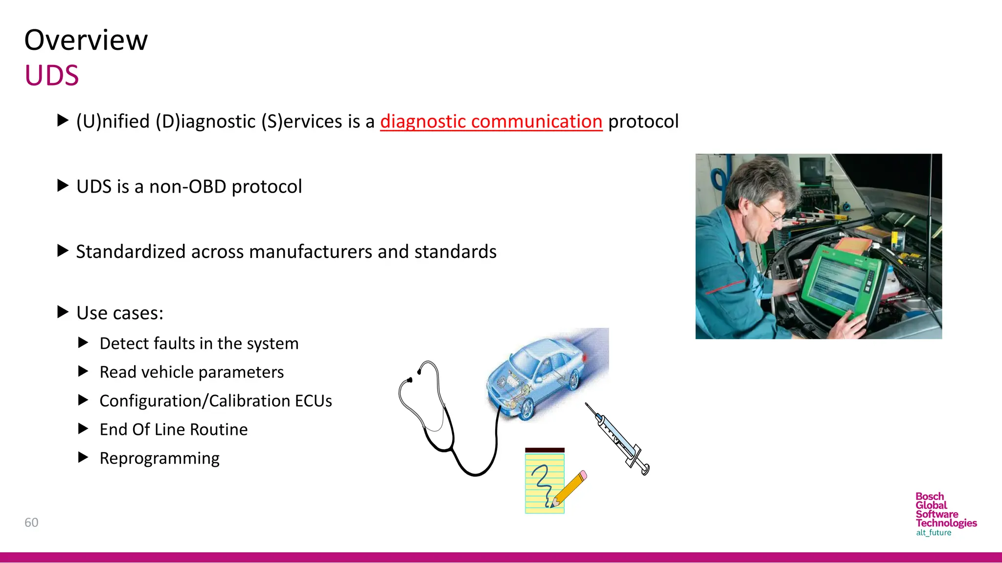
(U)nified (D)iagnostic(S)ervices is a diagnostic communication protocol
UDS is a non-OBD protocol
Standardized across manufacturers and standards
Use cases:
Detect faults in the system
Read vehicle parameters
Configuration/Calibration ECUs
End Of Line Routine
Reprogramming
Overview
Related ISO Standards
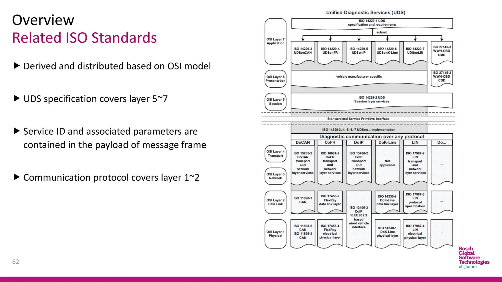
Derived and distributed based on OSI model
UDS specification covers layer 5~7
Service ID and associated parameters are
contained in the payload of message frame
Communication protocol covers layer 1~2
62
63.
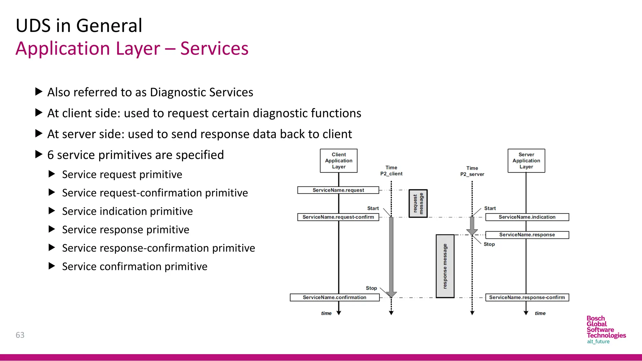
Application Layer –Services
UDS in General
63
Also referred to as Diagnostic Services
At client side: used to request certain diagnostic functions
At server side: used to send response data back to client
6 service primitives are specified
Service request primitive
Service request-confirmation primitive
Service indication primitive
Service response primitive
Service response-confirmation primitive
Service confirmation primitive
64.
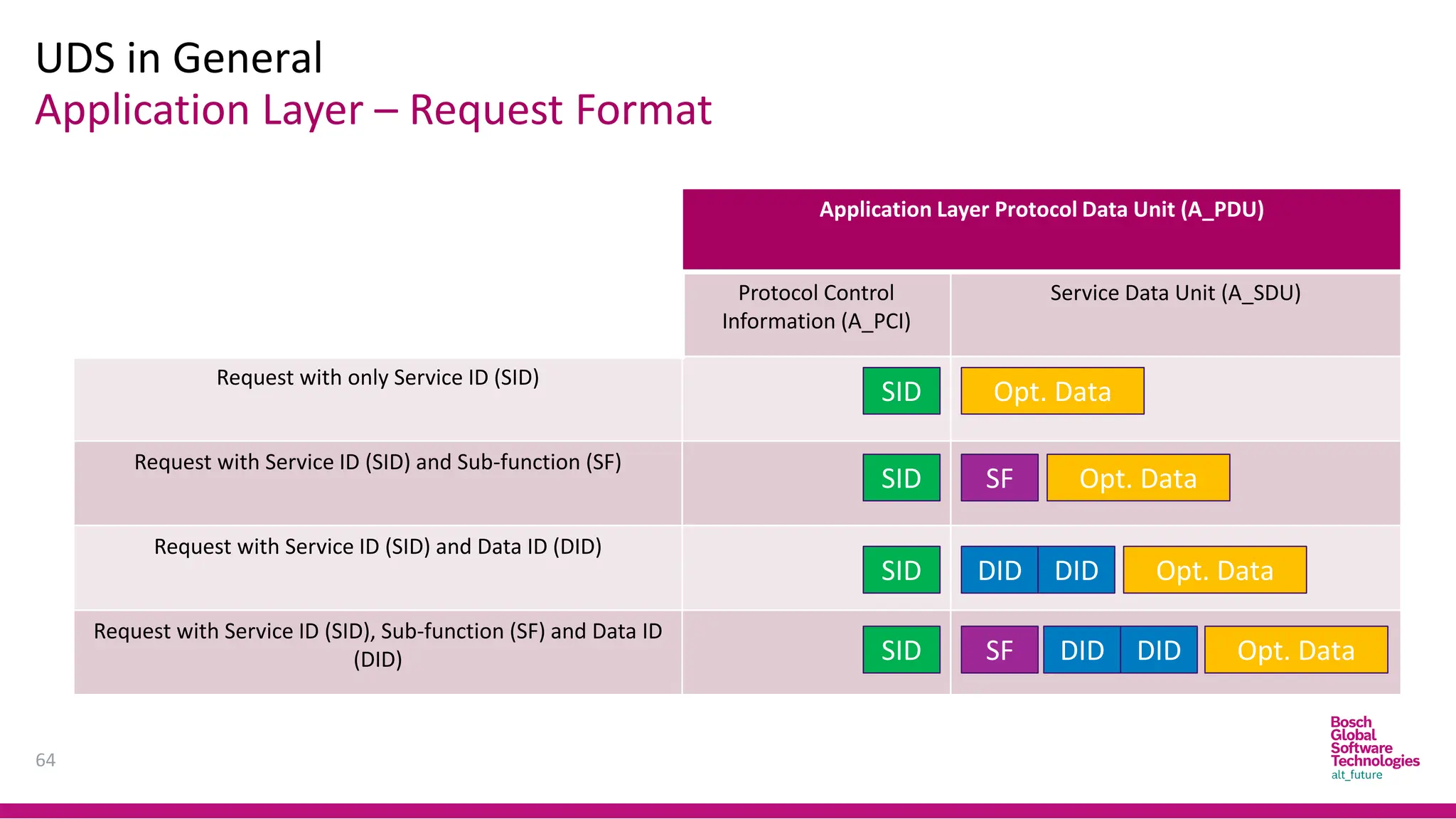
Application Layer –Request Format
UDS in General
64
Application Layer Protocol Data Unit (A_PDU)
Protocol Control
Information (A_PCI)
Service Data Unit (A_SDU)
Request with only Service ID (SID)
Request with Service ID (SID) and Sub-function (SF)
Request with Service ID (SID) and Data ID (DID)
Request with Service ID (SID), Sub-function (SF) and Data ID
(DID)
SID
SID
SID
SID
Opt. Data
Opt. Data
SF
Opt. Data
Opt. Data
SF
DID DID
DID DID
65.
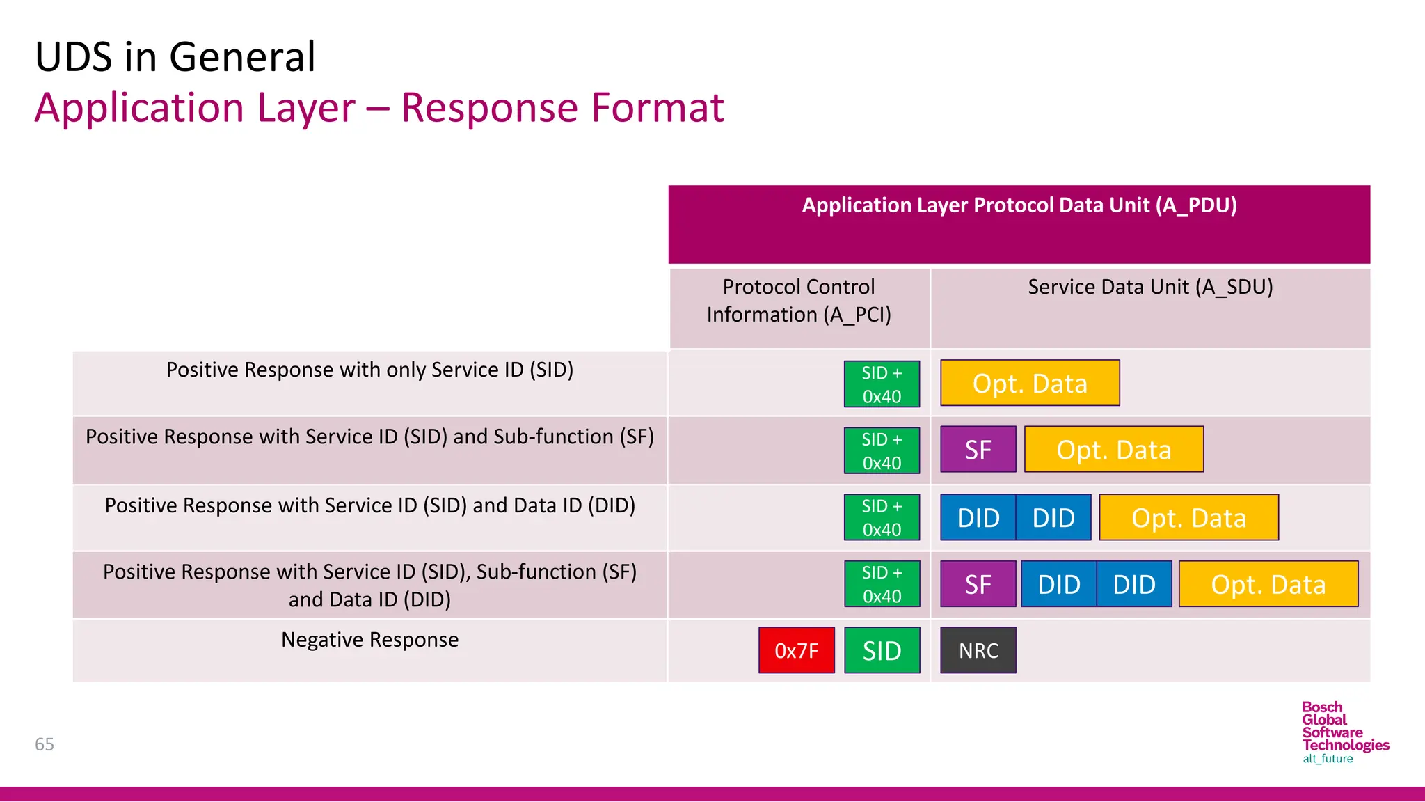
Application Layer –Response Format
UDS in General
65
Application Layer Protocol Data Unit (A_PDU)
Protocol Control
Information (A_PCI)
Service Data Unit (A_SDU)
Positive Response with only Service ID (SID)
Positive Response with Service ID (SID) and Sub-function (SF)
Positive Response with Service ID (SID) and Data ID (DID)
Positive Response with Service ID (SID), Sub-function (SF)
and Data ID (DID)
Negative Response
SID +
0x40
Opt. Data
Opt. Data
SF
Opt. Data
Opt. Data
SF
DID DID
DID DID
SID
0x7F NRC
SID +
0x40
SID +
0x40
SID +
0x40
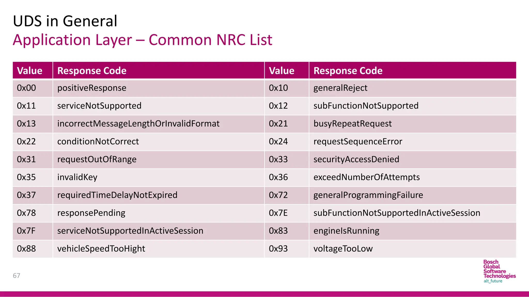
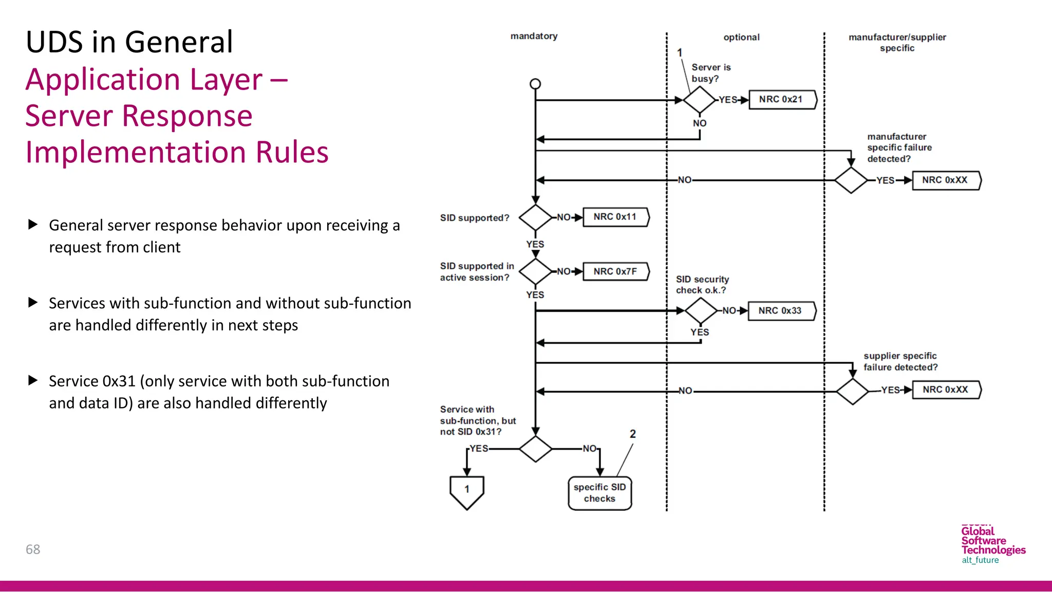
Application Layer –
ServerResponse
Implementation Rules
UDS in General
68
General server response behavior upon receiving a
request from client
Services with sub-function and without sub-function
are handled differently in next steps
Service 0x31 (only service with both sub-function
and data ID) are also handled differently
69.
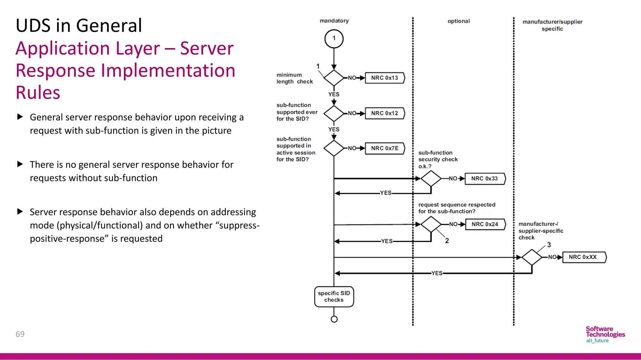
Application Layer –Server
Response Implementation
Rules
UDS in General
69
General server response behavior upon receiving a
request with sub-function is given in the picture
There is no general server response behavior for
requests without sub-function
Server response behavior also depends on addressing
mode (physical/functional) and on whether “suppress-
positive-response” is requested
70.
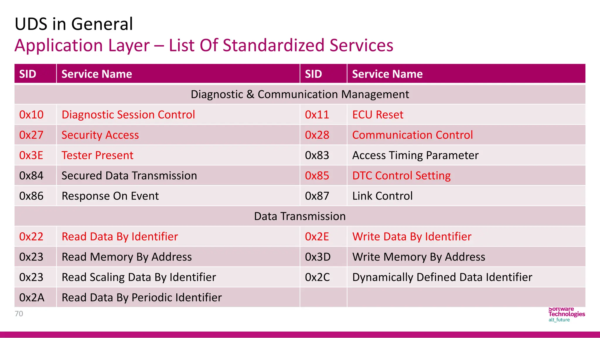
Application Layer –List Of Standardized Services
UDS in General
70
SID Service Name SID Service Name
Diagnostic & Communication Management
0x10 Diagnostic Session Control 0x11 ECU Reset
0x27 Security Access 0x28 Communication Control
0x3E Tester Present 0x83 Access Timing Parameter
0x84 Secured Data Transmission 0x85 DTC Control Setting
0x86 Response On Event 0x87 Link Control
Data Transmission
0x22 Read Data By Identifier 0x2E Write Data By Identifier
0x23 Read Memory By Address 0x3D Write Memory By Address
0x23 Read Scaling Data By Identifier 0x2C Dynamically Defined Data Identifier
0x2A Read Data By Periodic Identifier
71.
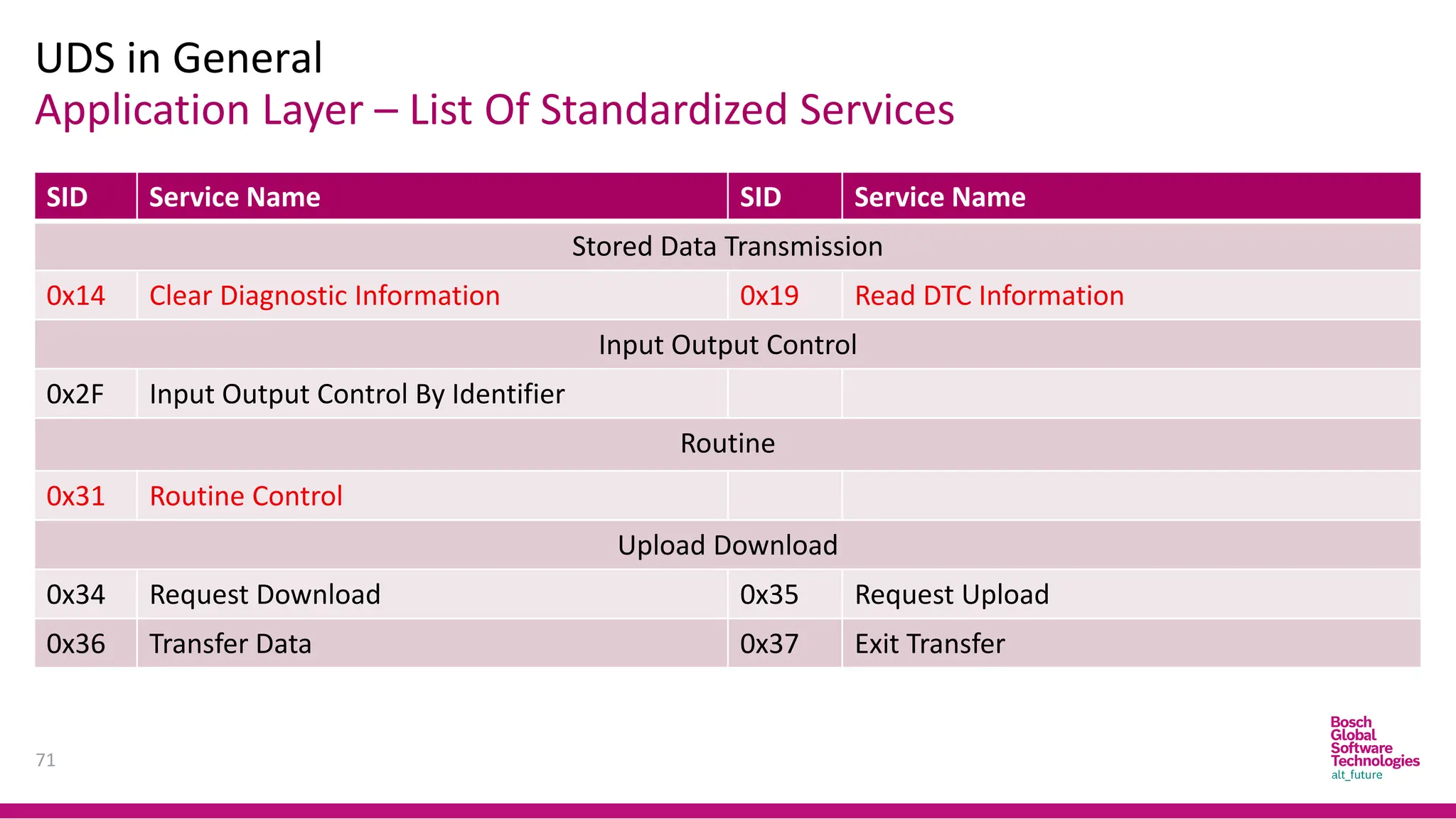
Application Layer –List Of Standardized Services
UDS in General
71
SID Service Name SID Service Name
Stored Data Transmission
0x14 Clear Diagnostic Information 0x19 Read DTC Information
Input Output Control
0x2F Input Output Control By Identifier
Routine
0x31 Routine Control
Upload Download
0x34 Request Download 0x35 Request Upload
0x36 Transfer Data 0x37 Exit Transfer
72.
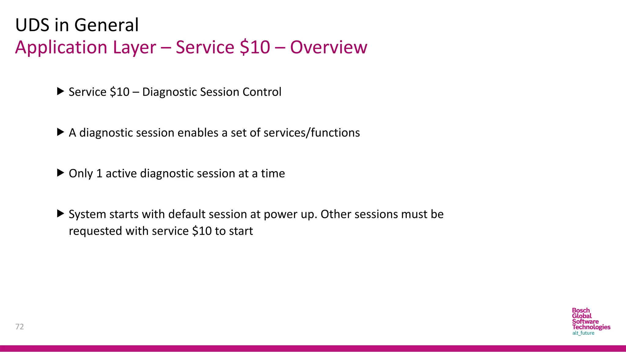
Application Layer –Service $10 – Overview
UDS in General
72
Service $10 – Diagnostic Session Control
A diagnostic session enables a set of services/functions
Only 1 active diagnostic session at a time
System starts with default session at power up. Other sessions must be
requested with service $10 to start
73.
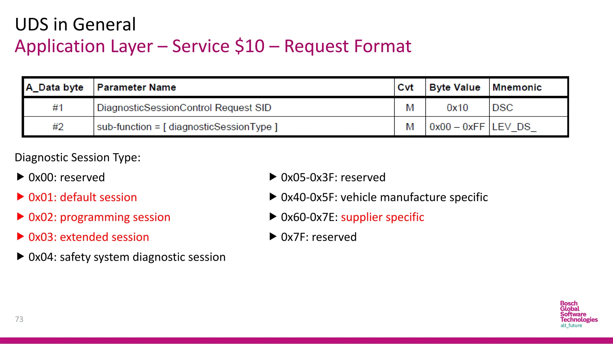
Application Layer –Service $10 – Request Format
UDS in General
73
Diagnostic Session Type:
0x00: reserved
0x01: default session
0x02: programming session
0x03: extended session
0x04: safety system diagnostic session
0x05-0x3F: reserved
0x40-0x5F: vehicle manufacture specific
0x60-0x7E: supplier specific
0x7F: reserved
74.
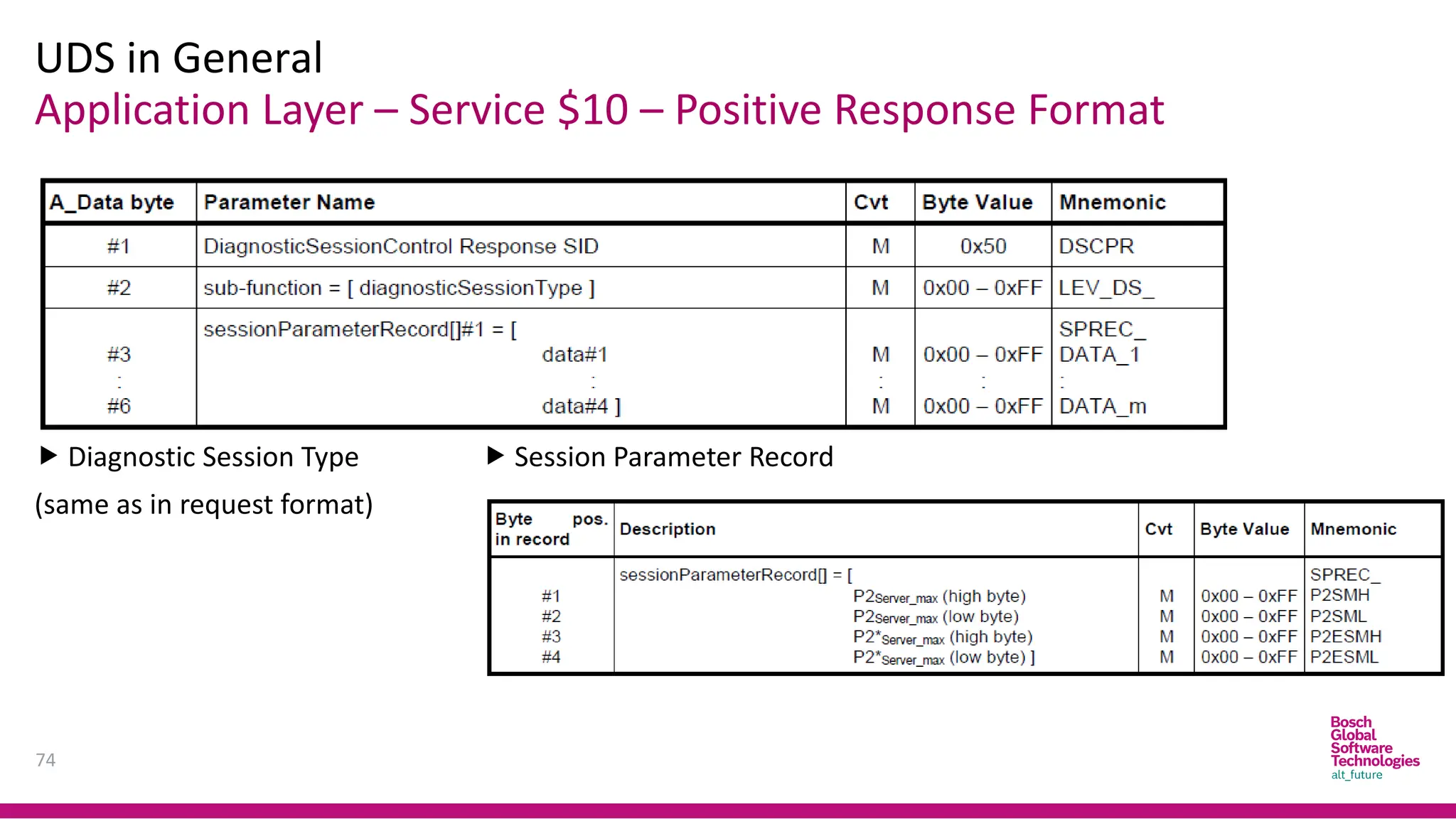
Application Layer –Service $10 – Positive Response Format
UDS in General
74
Diagnostic Session Type
(same as in request format)
Session Parameter Record
75.
Application Layer –Service $27 - Overview
UDS in General
75
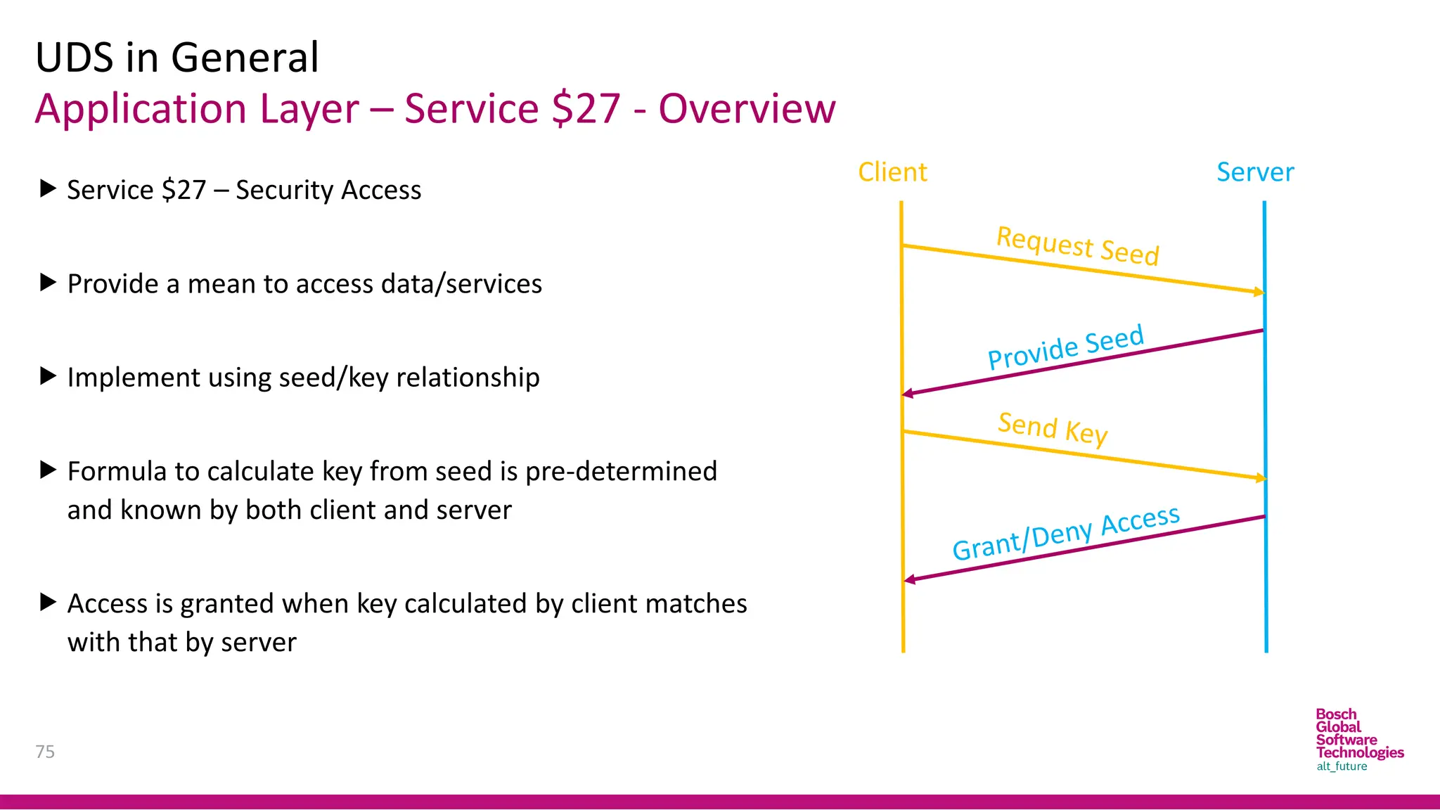
Service $27 – Security Access
Provide a mean to access data/services
Implement using seed/key relationship
Formula to calculate key from seed is pre-determined
and known by both client and server
Access is granted when key calculated by client matches
with that by server
Client Server
76.
Application Layer –Service $27 - Overview
UDS in General
76
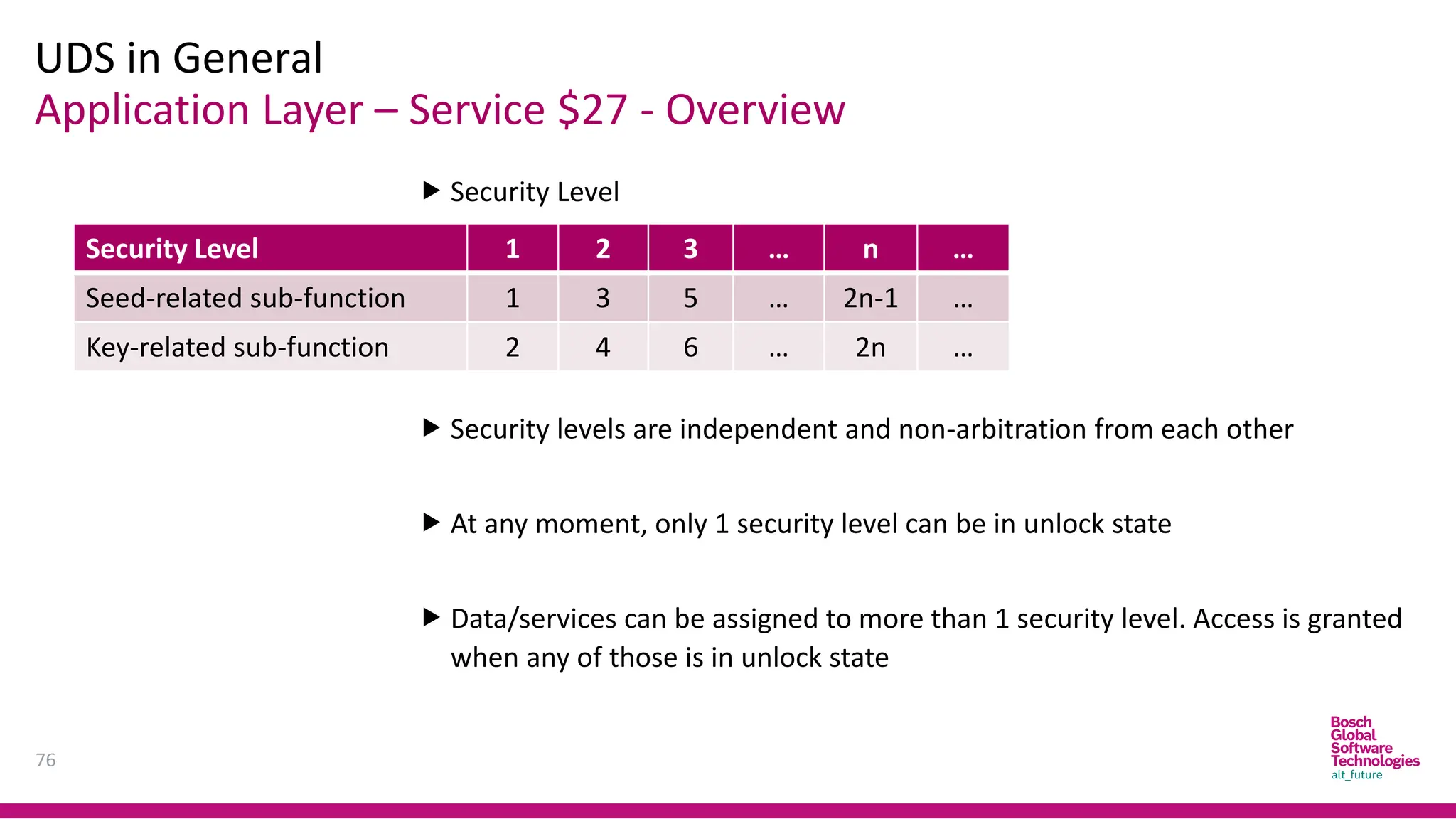
Security Level
Security levels are independent and non-arbitration from each other
At any moment, only 1 security level can be in unlock state
Data/services can be assigned to more than 1 security level. Access is granted
when any of those is in unlock state
Security Level 1 2 3 … n …
Seed-related sub-function 1 3 5 … 2n-1 …
Key-related sub-function 2 4 6 … 2n …
77.
Application Layer –Service $27 – Request Format
UDS in General
77
Security Access Data
Record (optional):
information about the
seed
78.
Application Layer –Service $27 – Response Format
UDS in General
78
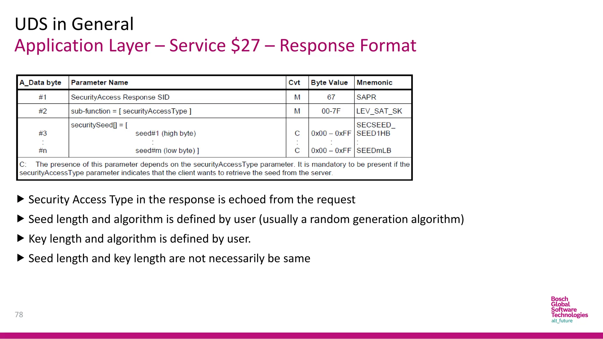
Security Access Type in the response is echoed from the request
Seed length and algorithm is defined by user (usually a random generation algorithm)
Key length and algorithm is defined by user.
Seed length and key length are not necessarily be same
79.
Application Layer –Service $22/$2E – Overview
UDS in General
79
Service $22 – Read Data by Identifier
Service $2E – Write Data by Identifier
Data Identifier (DID): 2 byte – mark for an internal location of a data record
DID along with referred data length and format are pre-defined by user
Service $2E might involve NVM-related services to store data
Service $2E might involve certain security check methods
80.
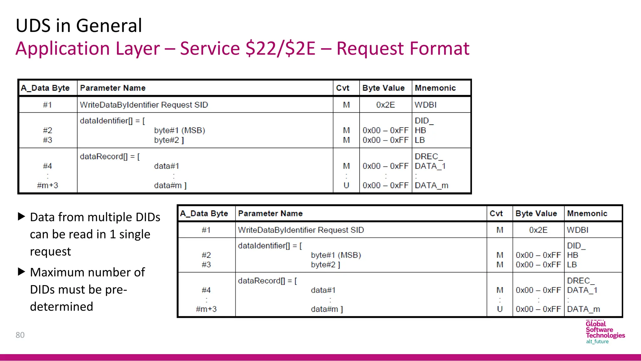
Application Layer –Service $22/$2E – Request Format
UDS in General
80
Data from multiple DIDs
can be read in 1 single
request
Maximum number of
DIDs must be pre-
determined
81.
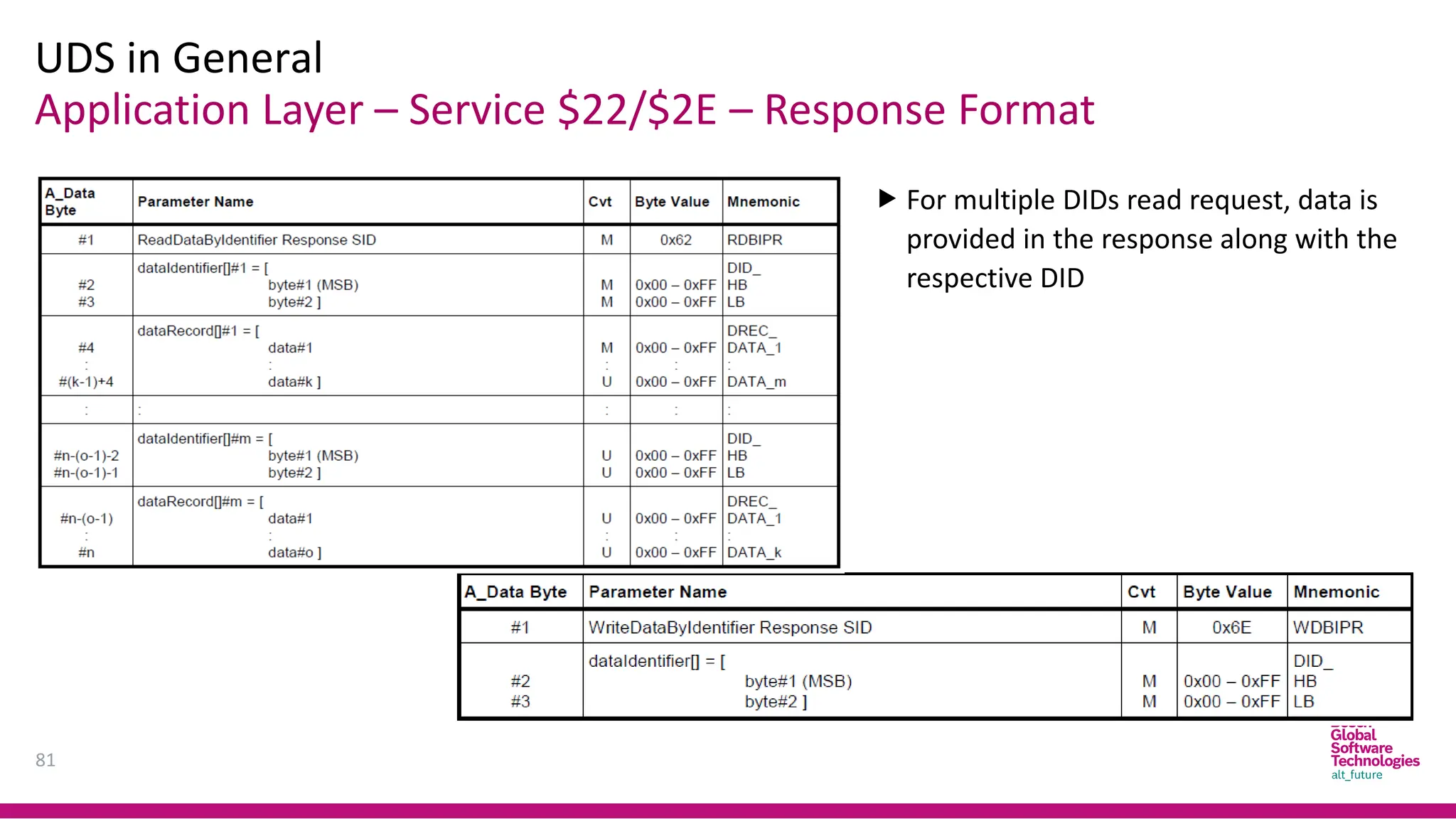
Application Layer –Service $22/$2E – Response Format
UDS in General
81
For multiple DIDs read request, data is
provided in the response along with the
respective DID
82.
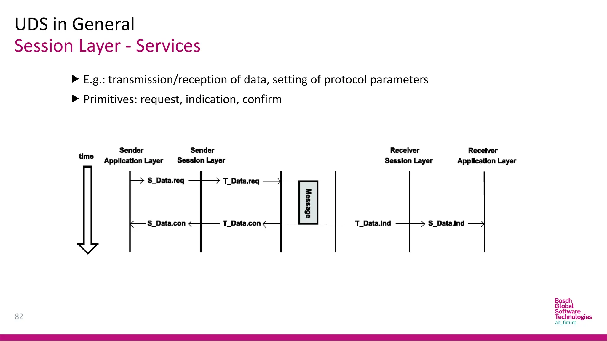
Session Layer -Services
UDS in General
82
E.g.: transmission/reception of data, setting of protocol parameters
Primitives: request, indication, confirm
83.
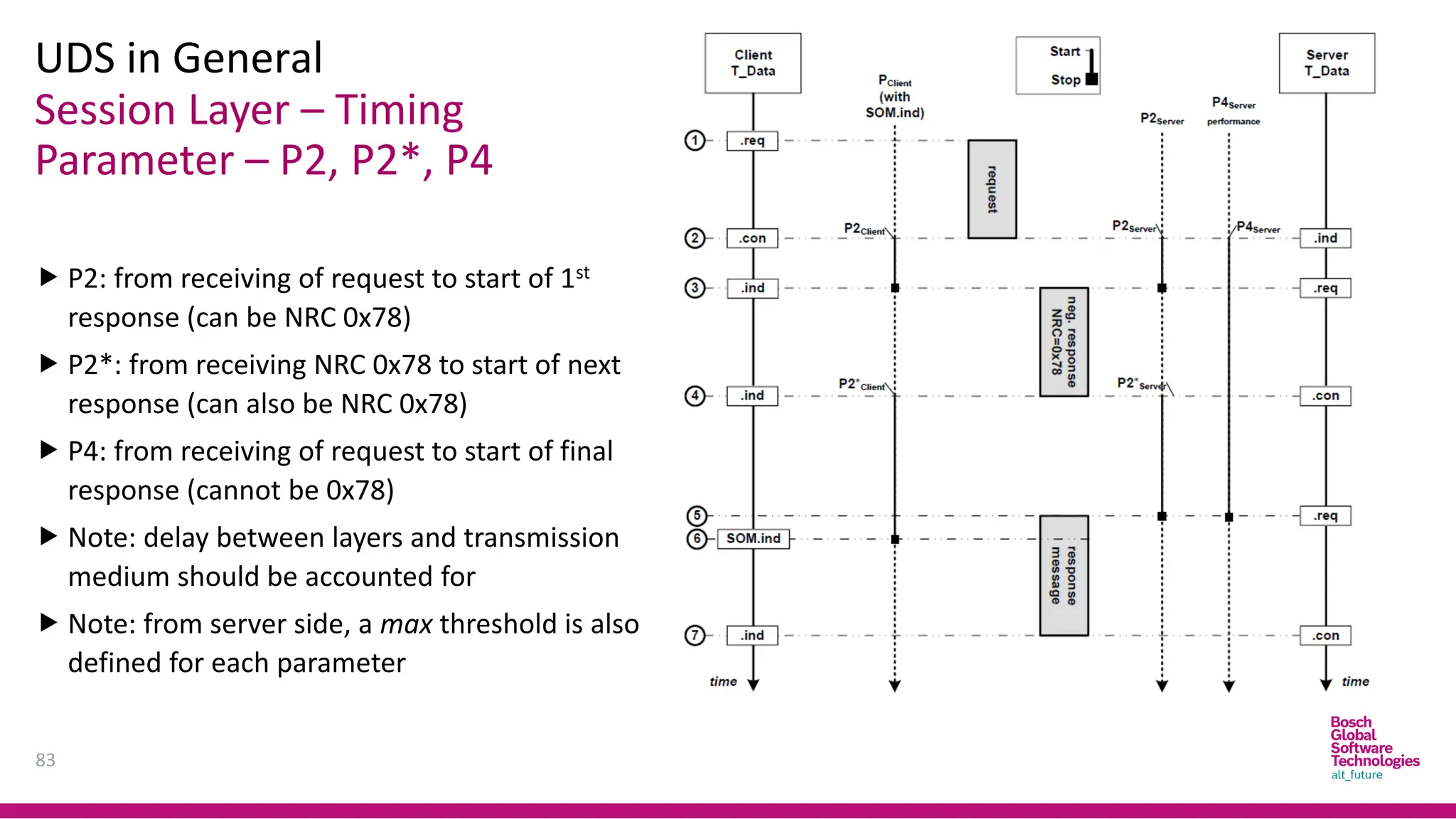
Session Layer –Timing
Parameter – P2, P2*, P4
UDS in General
83
P2: from receiving of request to start of 1st
response (can be NRC 0x78)
P2*: from receiving NRC 0x78 to start of next
response (can also be NRC 0x78)
P4: from receiving of request to start of final
response (cannot be 0x78)
Note: delay between layers and transmission
medium should be accounted for
Note: from server side, a max threshold is also
defined for each parameter
84.
Application Layer
UDS inCAN Implementation
84
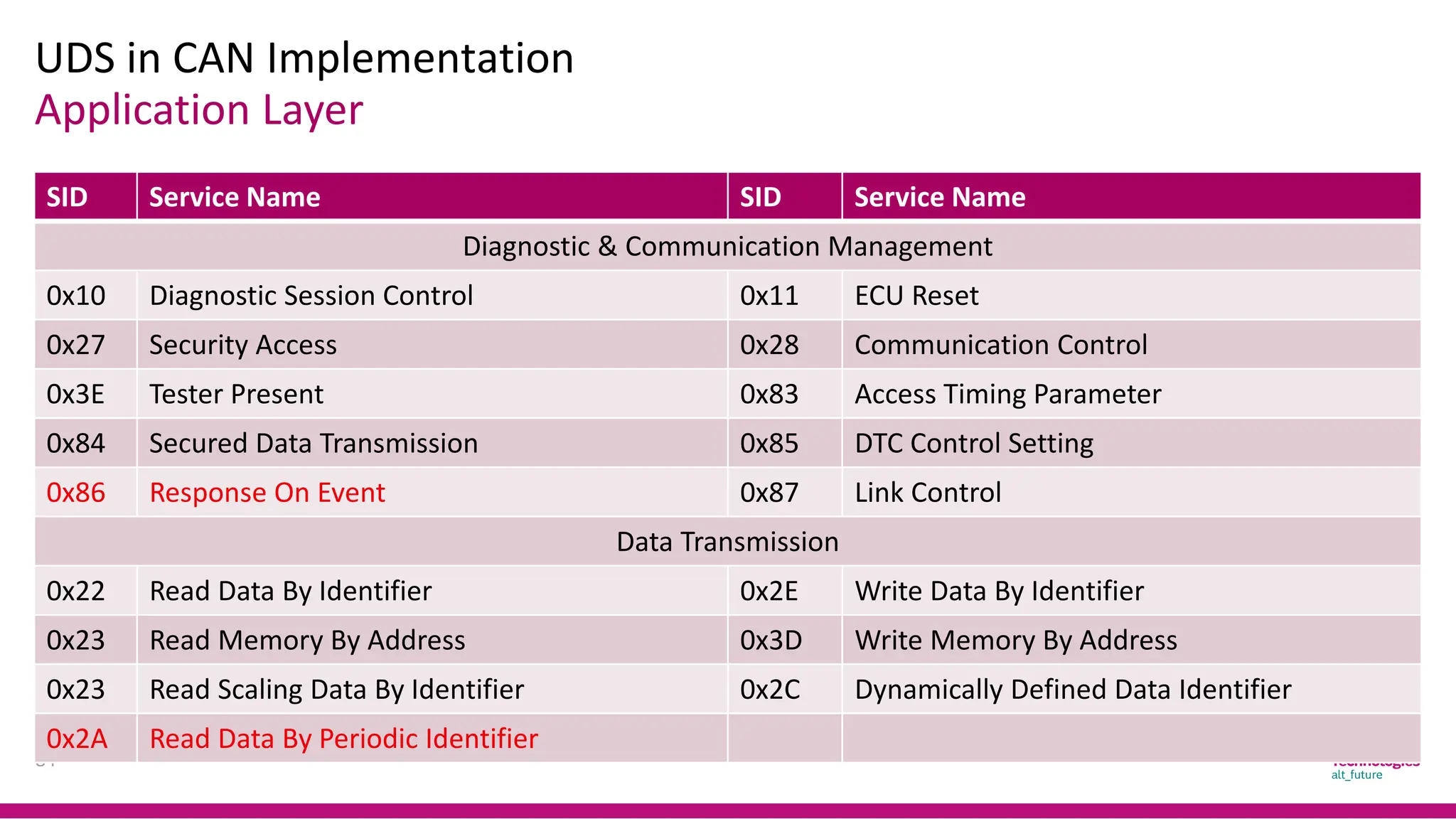
SID Service Name SID Service Name
Diagnostic & Communication Management
0x10 Diagnostic Session Control 0x11 ECU Reset
0x27 Security Access 0x28 Communication Control
0x3E Tester Present 0x83 Access Timing Parameter
0x84 Secured Data Transmission 0x85 DTC Control Setting
0x86 Response On Event 0x87 Link Control
Data Transmission
0x22 Read Data By Identifier 0x2E Write Data By Identifier
0x23 Read Memory By Address 0x3D Write Memory By Address
0x23 Read Scaling Data By Identifier 0x2C Dynamically Defined Data Identifier
0x2A Read Data By Periodic Identifier
85.
Application Layer
UDS inCAN Implementation
85
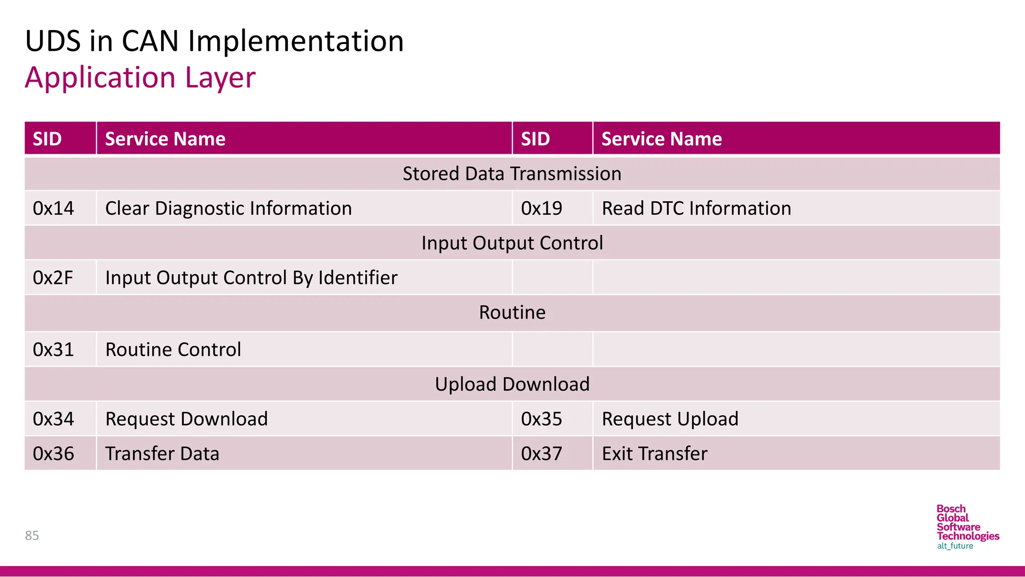
SID Service Name SID Service Name
Stored Data Transmission
0x14 Clear Diagnostic Information 0x19 Read DTC Information
Input Output Control
0x2F Input Output Control By Identifier
Routine
0x31 Routine Control
Upload Download
0x34 Request Download 0x35 Request Upload
0x36 Transfer Data 0x37 Exit Transfer
Agenda
88
1. Overview
1. Diagnosticover any protocol
2. OSI encapsulation model
2. Diagnostic over CAN
1. Problem
2. Single-frame transmission
3. Multi-frame transmission
4. N_PDU definition
5. Timing parameters
89.
Diagnostic Over AnyProtocol
Overview
89
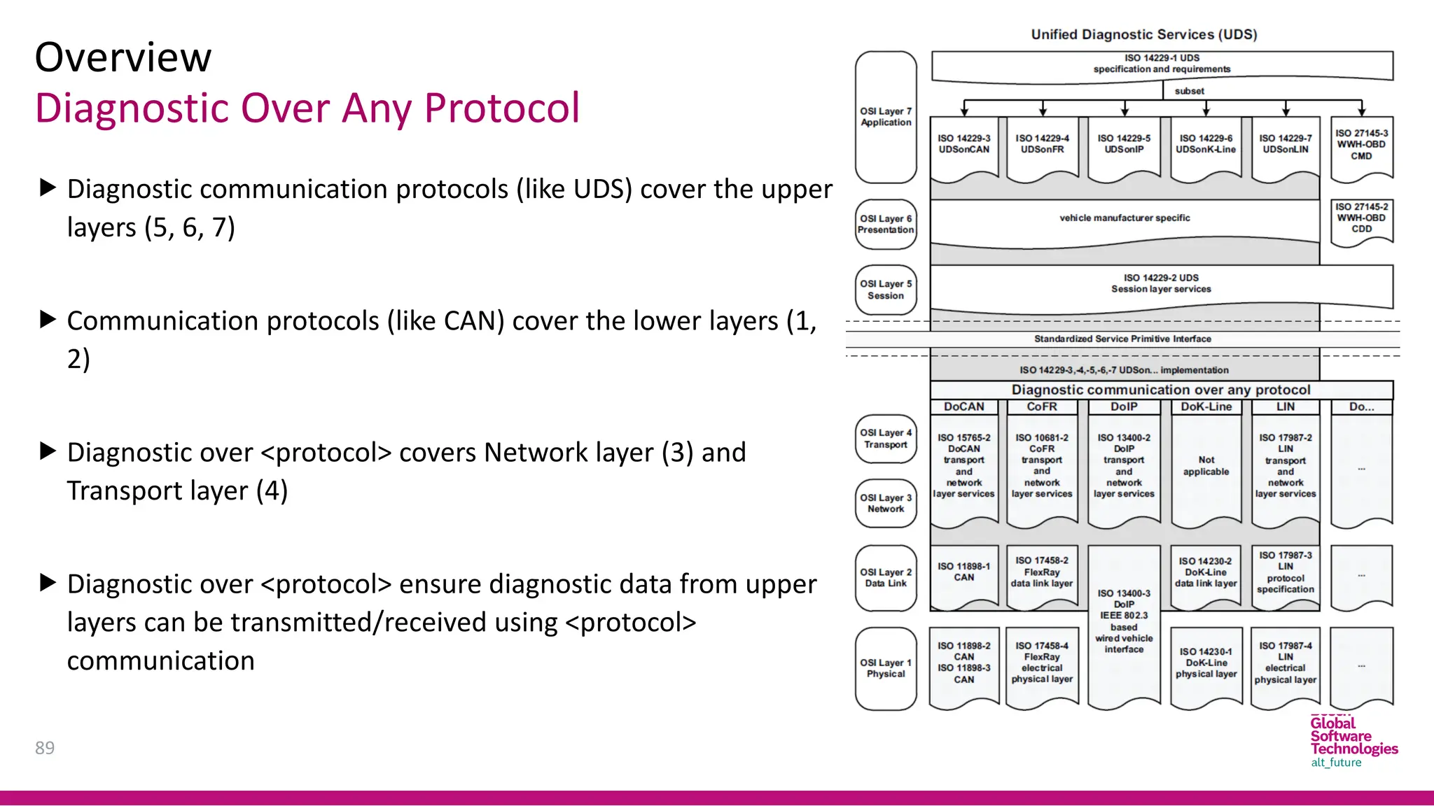
Diagnostic communication protocols (like UDS) cover the upper
layers (5, 6, 7)
Communication protocols (like CAN) cover the lower layers (1,
2)
Diagnostic over <protocol> covers Network layer (3) and
Transport layer (4)
Diagnostic over <protocol> ensure diagnostic data from upper
layers can be transmitted/received using <protocol>
communication
90.
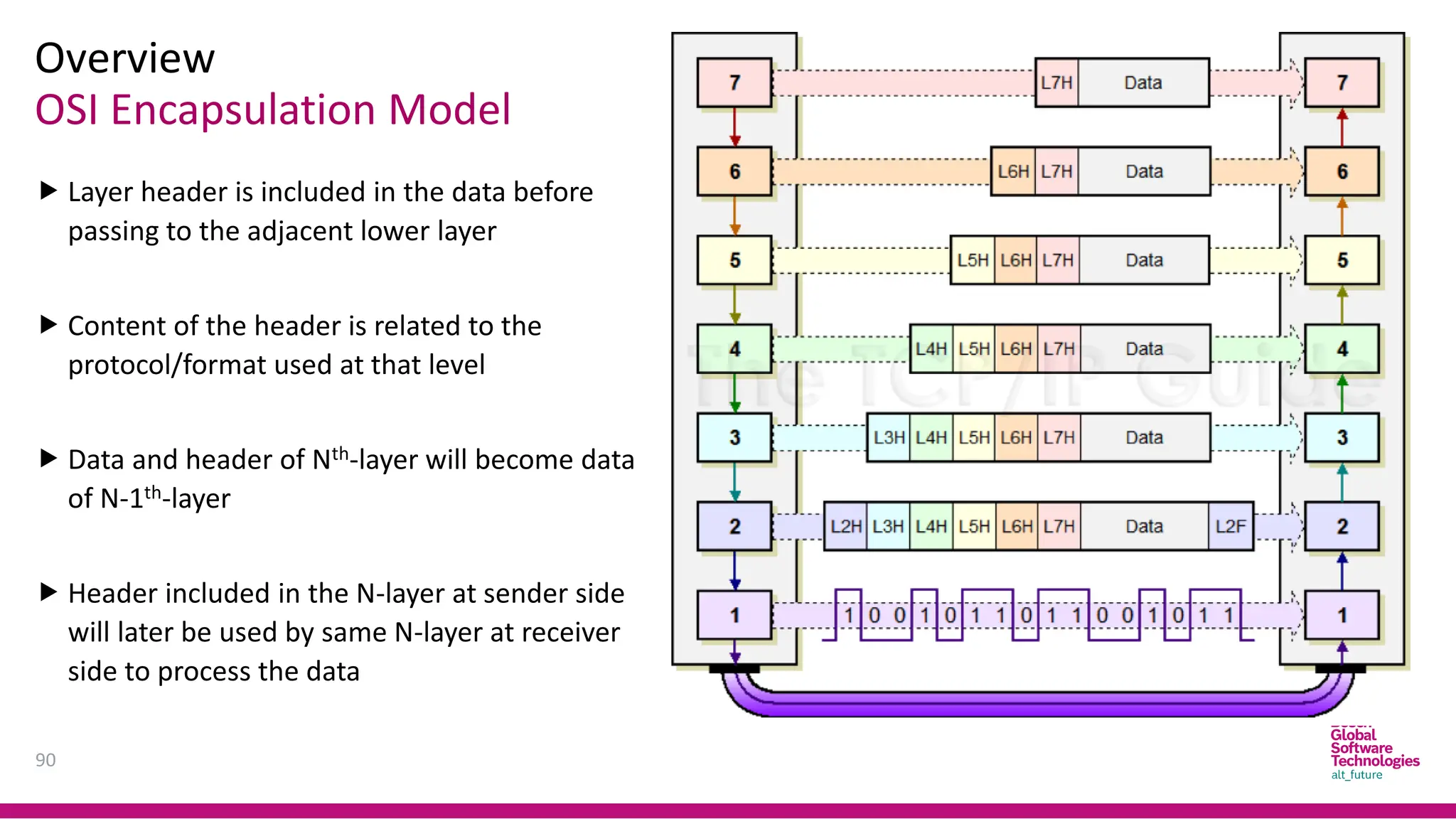
OSI Encapsulation Model
Overview
90
Layer header is included in the data before
passing to the adjacent lower layer
Content of the header is related to the
protocol/format used at that level
Data and header of Nth-layer will become data
of N-1th-layer
Header included in the N-layer at sender side
will later be used by same N-layer at receiver
side to process the data
91.
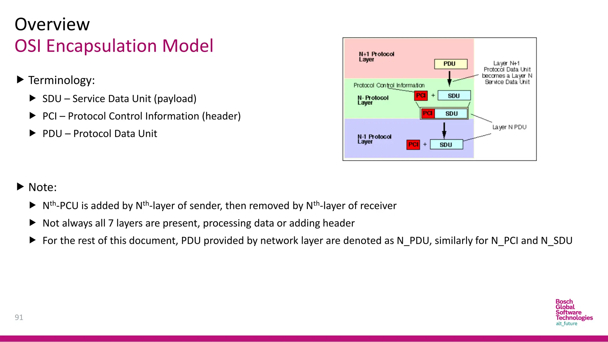
OSI Encapsulation Model
Overview
91
Terminology:
SDU – Service Data Unit (payload)
PCI – Protocol Control Information (header)
PDU – Protocol Data Unit
Note:
Nth-PCU is added by Nth-layer of sender, then removed by Nth-layer of receiver
Not always all 7 layers are present, processing data or adding header
For the rest of this document, PDU provided by network layer are denoted as N_PDU, similarly for N_PCI and N_SDU
92.
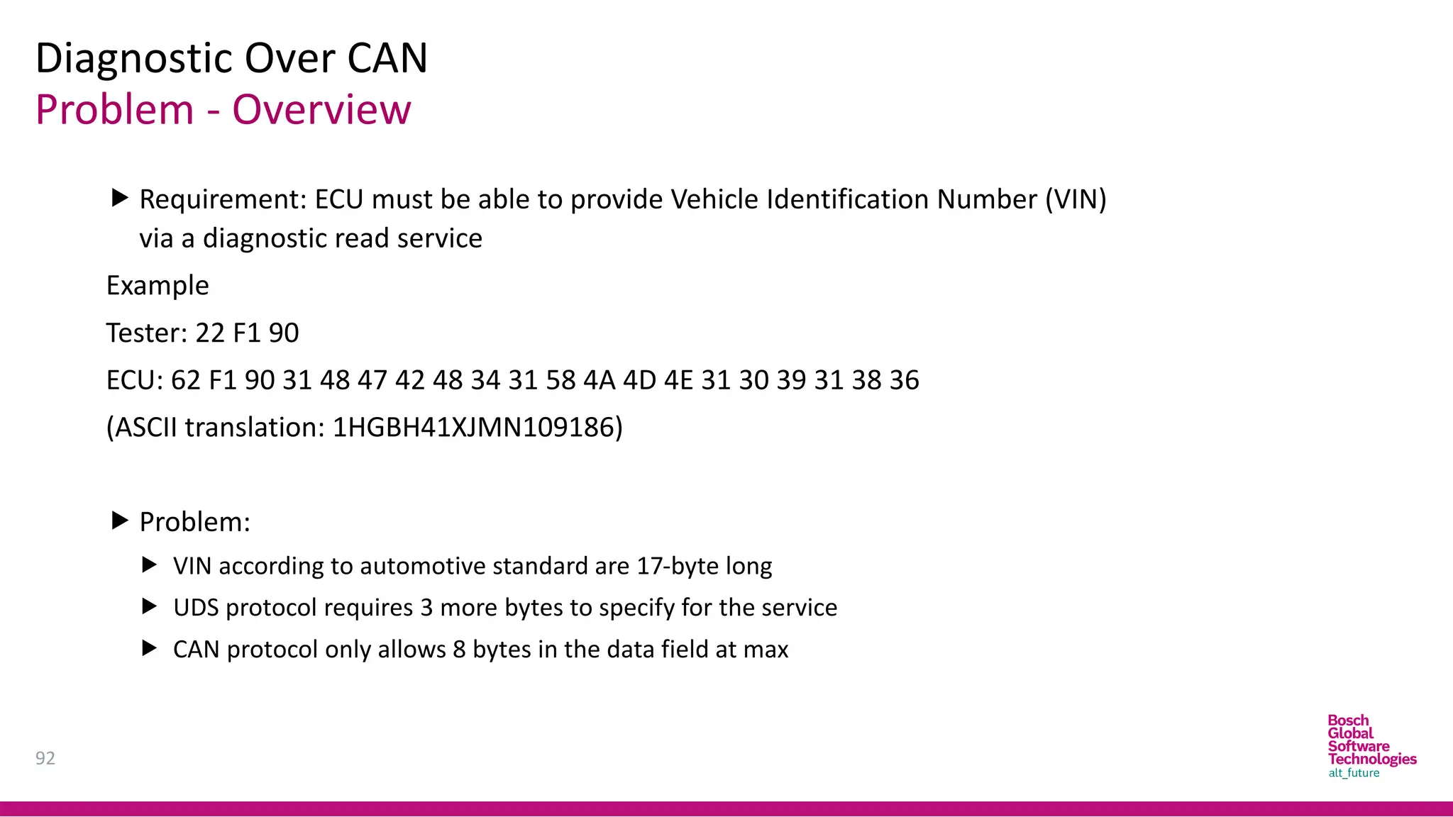
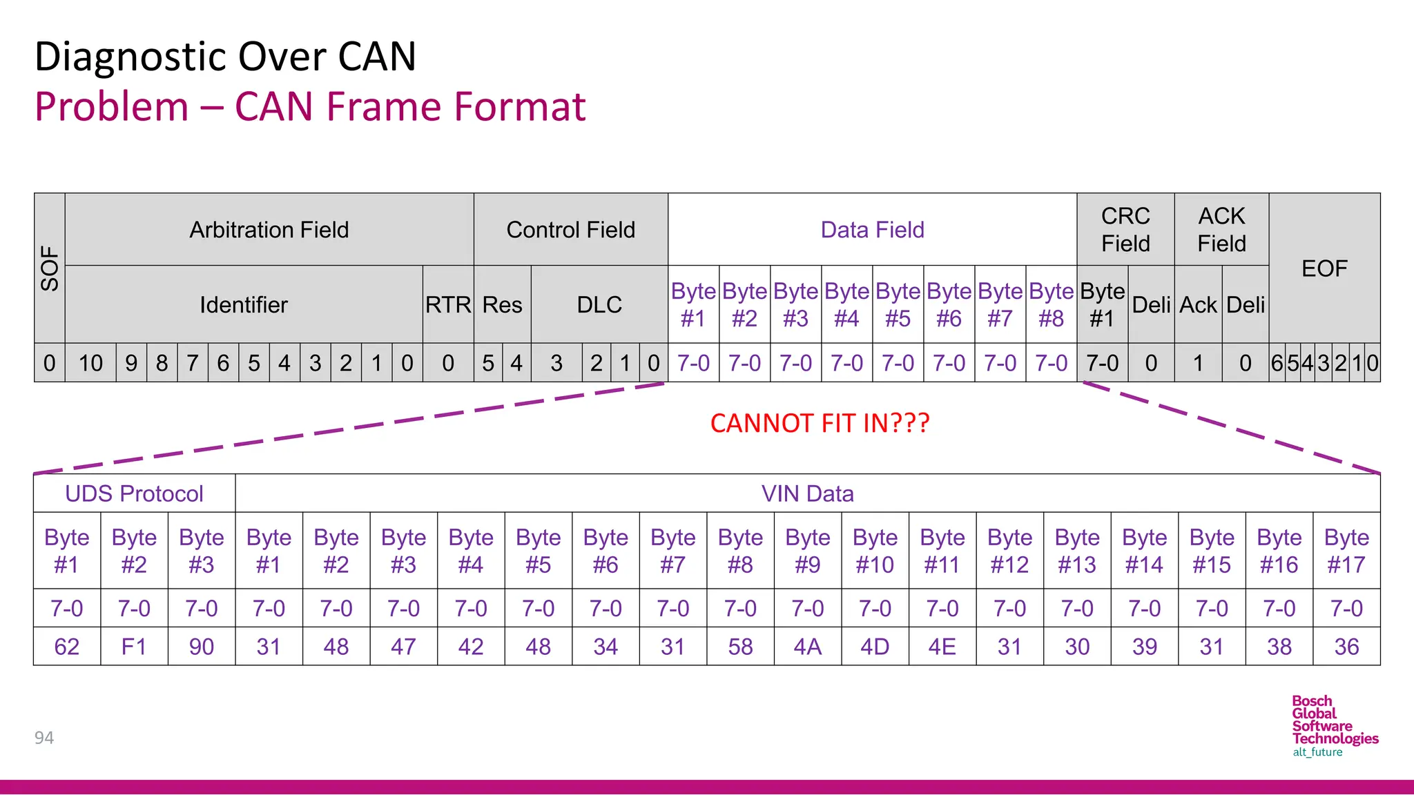
Problem - Overview
DiagnosticOver CAN
92
Requirement: ECU must be able to provide Vehicle Identification Number (VIN)
via a diagnostic read service
Example
Tester: 22 F1 90
ECU: 62 F1 90 31 48 47 42 48 34 31 58 4A 4D 4E 31 30 39 31 38 36
(ASCII translation: 1HGBH41XJMN109186)
Problem:
VIN according to automotive standard are 17-byte long
UDS protocol requires 3 more bytes to specify for the service
CAN protocol only allows 8 bytes in the data field at max
Problem – CANFrame Format
Diagnostic Over CAN
94
SOF
Arbitration Field Control Field Data Field
CRC
Field
ACK
Field
EOF
Identifier RTR Res DLC
Byte
#1
Byte
#2
Byte
#3
Byte
#4
Byte
#5
Byte
#6
Byte
#7
Byte
#8
Byte
#1
Deli Ack Deli
0 10 9 8 7 6 5 4 3 2 1 0 0 5 4 3 2 1 0 7-0 7-0 7-0 7-0 7-0 7-0 7-0 7-0 7-0 0 1 0 6543 2 10
UDS Protocol VIN Data
Byte
#1
Byte
#2
Byte
#3
Byte
#1
Byte
#2
Byte
#3
Byte
#4
Byte
#5
Byte
#6
Byte
#7
Byte
#8
Byte
#9
Byte
#10
Byte
#11
Byte
#12
Byte
#13
Byte
#14
Byte
#15
Byte
#16
Byte
#17
7-0 7-0 7-0 7-0 7-0 7-0 7-0 7-0 7-0 7-0 7-0 7-0 7-0 7-0 7-0 7-0 7-0 7-0 7-0 7-0
62 F1 90 31 48 47 42 48 34 31 58 4A 4D 4E 31 30 39 31 38 36
CANNOT FIT IN???
95.
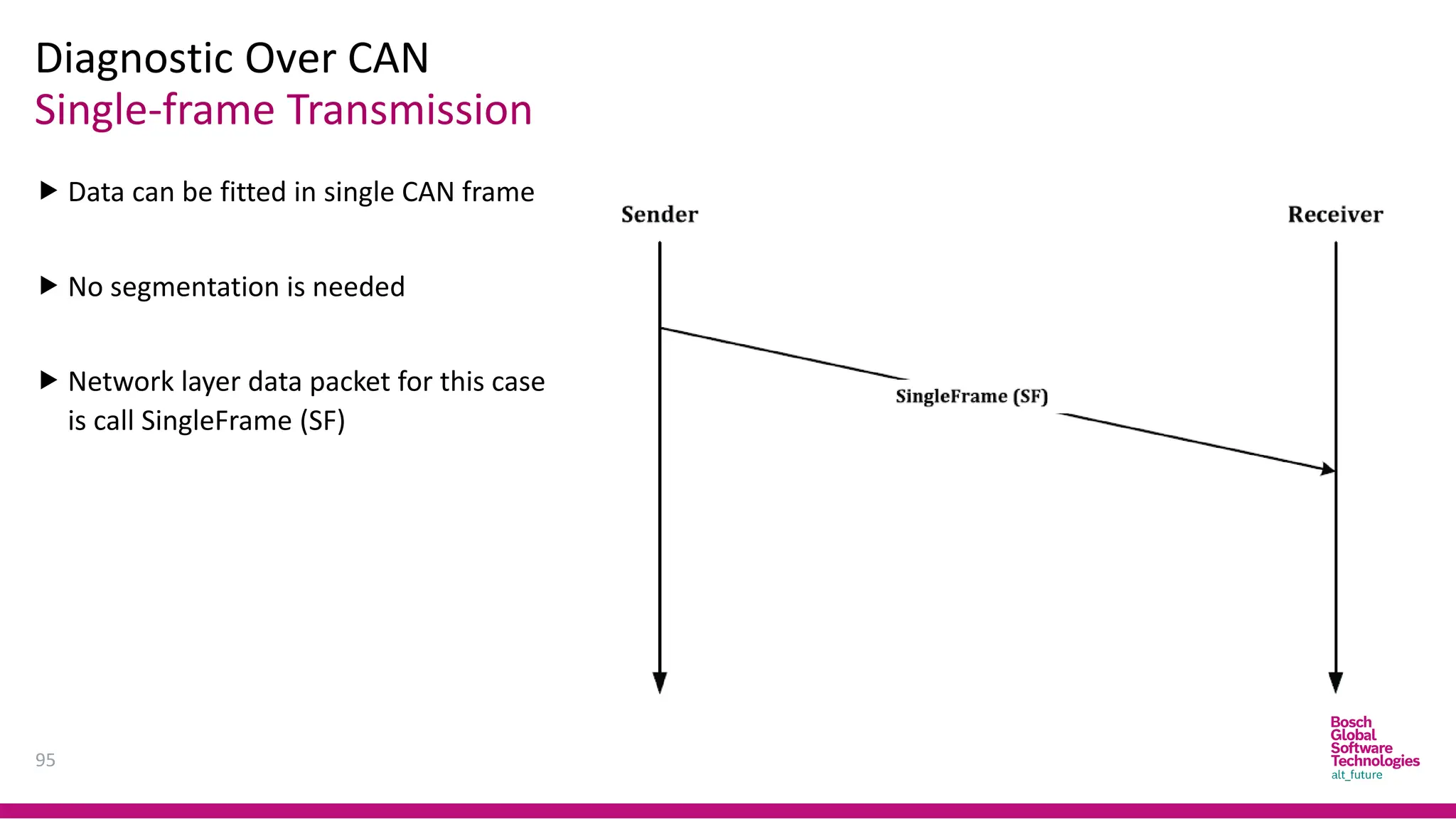
Single-frame Transmission
Diagnostic OverCAN
95
Data can be fitted in single CAN frame
No segmentation is needed
Network layer data packet for this case
is call SingleFrame (SF)
96.
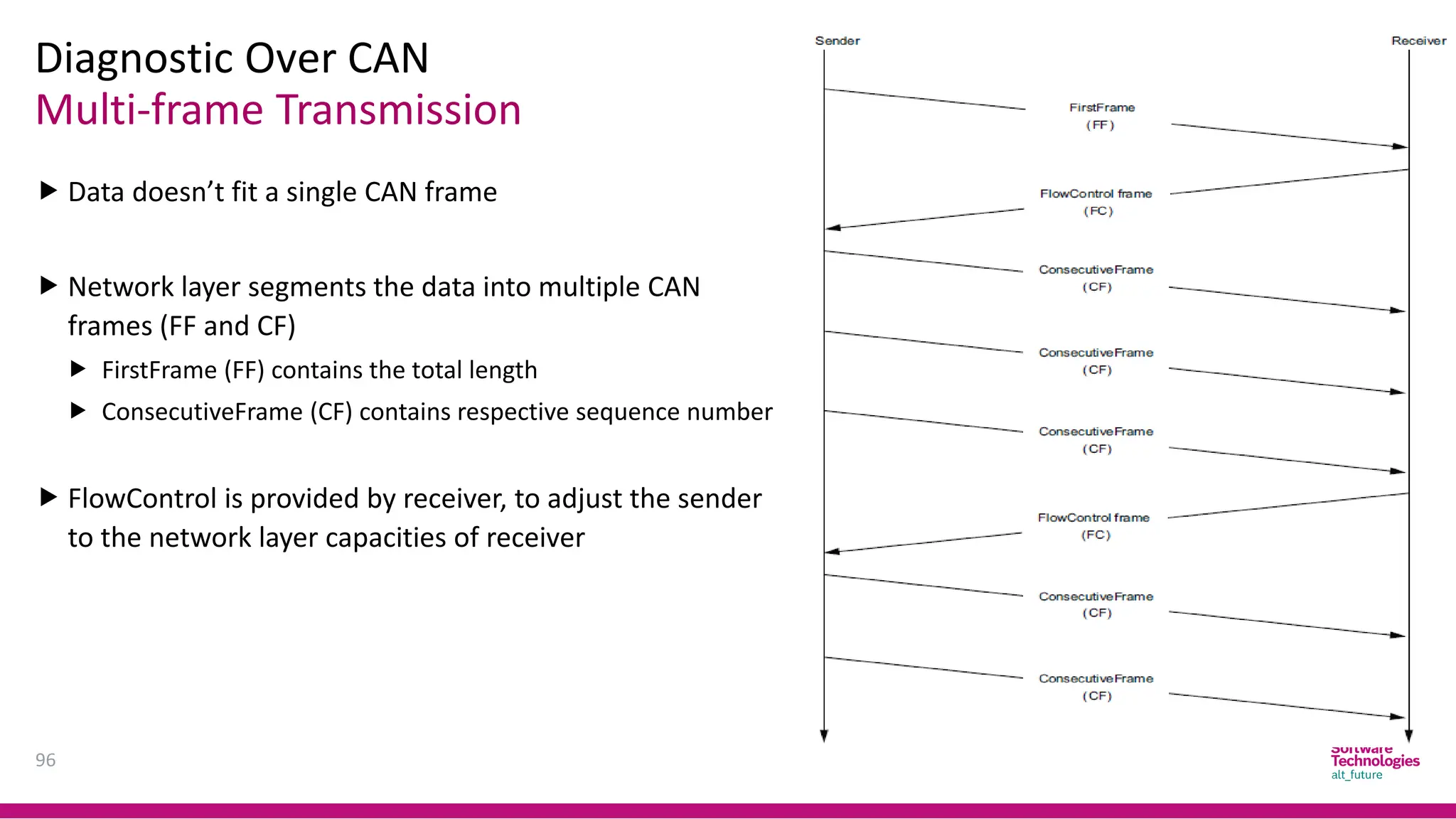
Multi-frame Transmission
Diagnostic OverCAN
96
Data doesn’t fit a single CAN frame
Network layer segments the data into multiple CAN
frames (FF and CF)
FirstFrame (FF) contains the total length
ConsecutiveFrame (CF) contains respective sequence number
FlowControl is provided by receiver, to adjust the sender
to the network layer capacities of receiver
97.
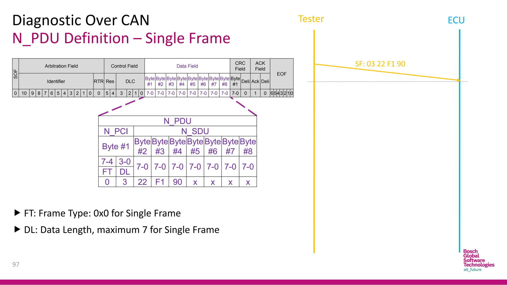
N_PDU Definition –Single Frame
Diagnostic Over CAN
97
SOF
Arbitration Field Control Field Data Field
CRC
Field
ACK
Field
EOF
Identifier RTR Res DLC
Byte
#1
Byte
#2
Byte
#3
Byte
#4
Byte
#5
Byte
#6
Byte
#7
Byte
#8
Byte
#1
Deli Ack Deli
0 10 9 8 7 6 5 4 3 2 1 0 0 5 4 3 2 1 0 7-0 7-0 7-0 7-0 7-0 7-0 7-0 7-0 7-0 0 1 0 6543 2 10
N_PDU
N_PCI N_SDU
Byte #1
Byte
#2
Byte
#3
Byte
#4
Byte
#5
Byte
#6
Byte
#7
Byte
#8
7-4 3-0
7-0 7-0 7-0 7-0 7-0 7-0 7-0
FT DL
0 3 22 F1 90 x x x x
FT: Frame Type: 0x0 for Single Frame
DL: Data Length, maximum 7 for Single Frame
SF: 03 22 F1 90
Tester ECU
98.
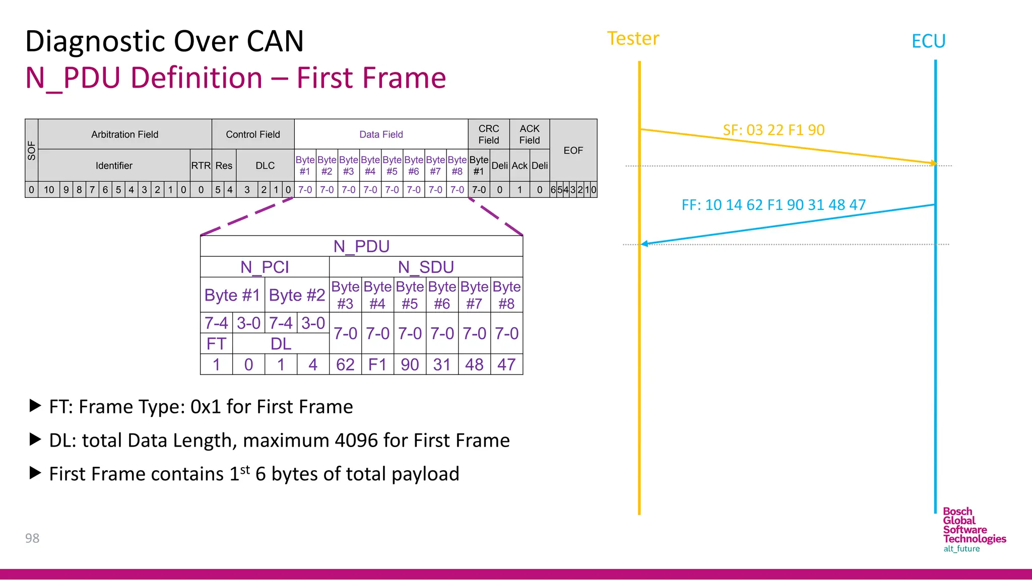
N_PDU Definition –First Frame
Diagnostic Over CAN
98
Tester ECU
SOF
Arbitration Field Control Field Data Field
CRC
Field
ACK
Field
EOF
Identifier RTR Res DLC
Byte
#1
Byte
#2
Byte
#3
Byte
#4
Byte
#5
Byte
#6
Byte
#7
Byte
#8
Byte
#1
Deli Ack Deli
0 10 9 8 7 6 5 4 3 2 1 0 0 5 4 3 2 1 0 7-0 7-0 7-0 7-0 7-0 7-0 7-0 7-0 7-0 0 1 0 6543 2 10
FT: Frame Type: 0x1 for First Frame
DL: total Data Length, maximum 4096 for First Frame
First Frame contains 1st 6 bytes of total payload
N_PDU
N_PCI N_SDU
Byte #1 Byte #2
Byte
#3
Byte
#4
Byte
#5
Byte
#6
Byte
#7
Byte
#8
7-4 3-0 7-4 3-0
7-0 7-0 7-0 7-0 7-0 7-0
FT DL
1 0 1 4 62 F1 90 31 48 47
FF: 10 14 62 F1 90 31 48 47
SF: 03 22 F1 90
99.
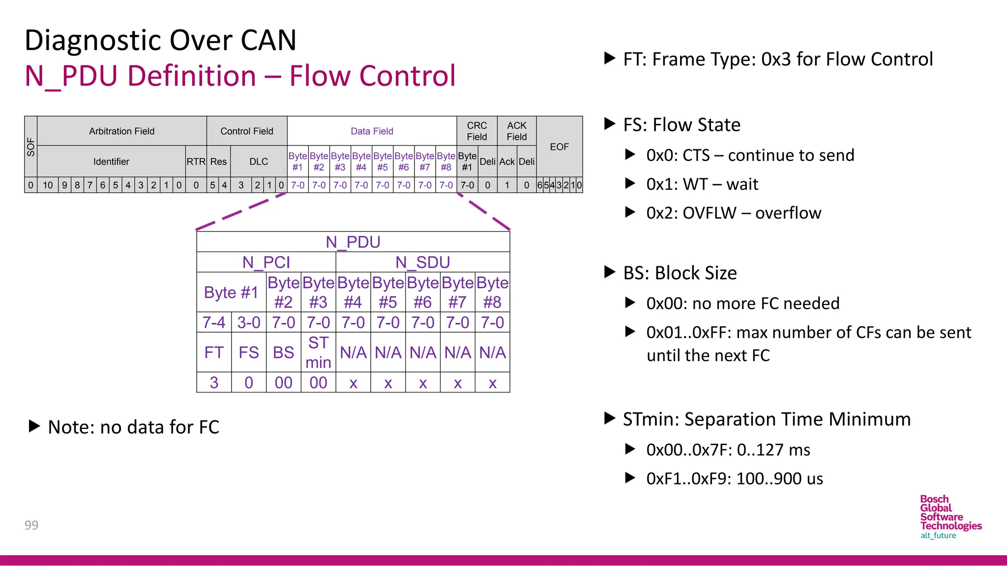
N_PDU Definition –Flow Control
Diagnostic Over CAN
99
SOF
Arbitration Field Control Field Data Field
CRC
Field
ACK
Field
EOF
Identifier RTR Res DLC
Byte
#1
Byte
#2
Byte
#3
Byte
#4
Byte
#5
Byte
#6
Byte
#7
Byte
#8
Byte
#1
Deli Ack Deli
0 10 9 8 7 6 5 4 3 2 1 0 0 5 4 3 2 1 0 7-0 7-0 7-0 7-0 7-0 7-0 7-0 7-0 7-0 0 1 0 6543 2 10
FT: Frame Type: 0x3 for Flow Control
FS: Flow State
0x0: CTS – continue to send
0x1: WT – wait
0x2: OVFLW – overflow
BS: Block Size
0x00: no more FC needed
0x01..0xFF: max number of CFs can be sent
until the next FC
STmin: Separation Time Minimum
0x00..0x7F: 0..127 ms
0xF1..0xF9: 100..900 us
N_PDU
N_PCI N_SDU
Byte #1
Byte
#2
Byte
#3
Byte
#4
Byte
#5
Byte
#6
Byte
#7
Byte
#8
7-4 3-0 7-0 7-0 7-0 7-0 7-0 7-0 7-0
FT FS BS
ST
min
N/A N/A N/A N/A N/A
3 0 00 00 x x x x x
Note: no data for FC
100.
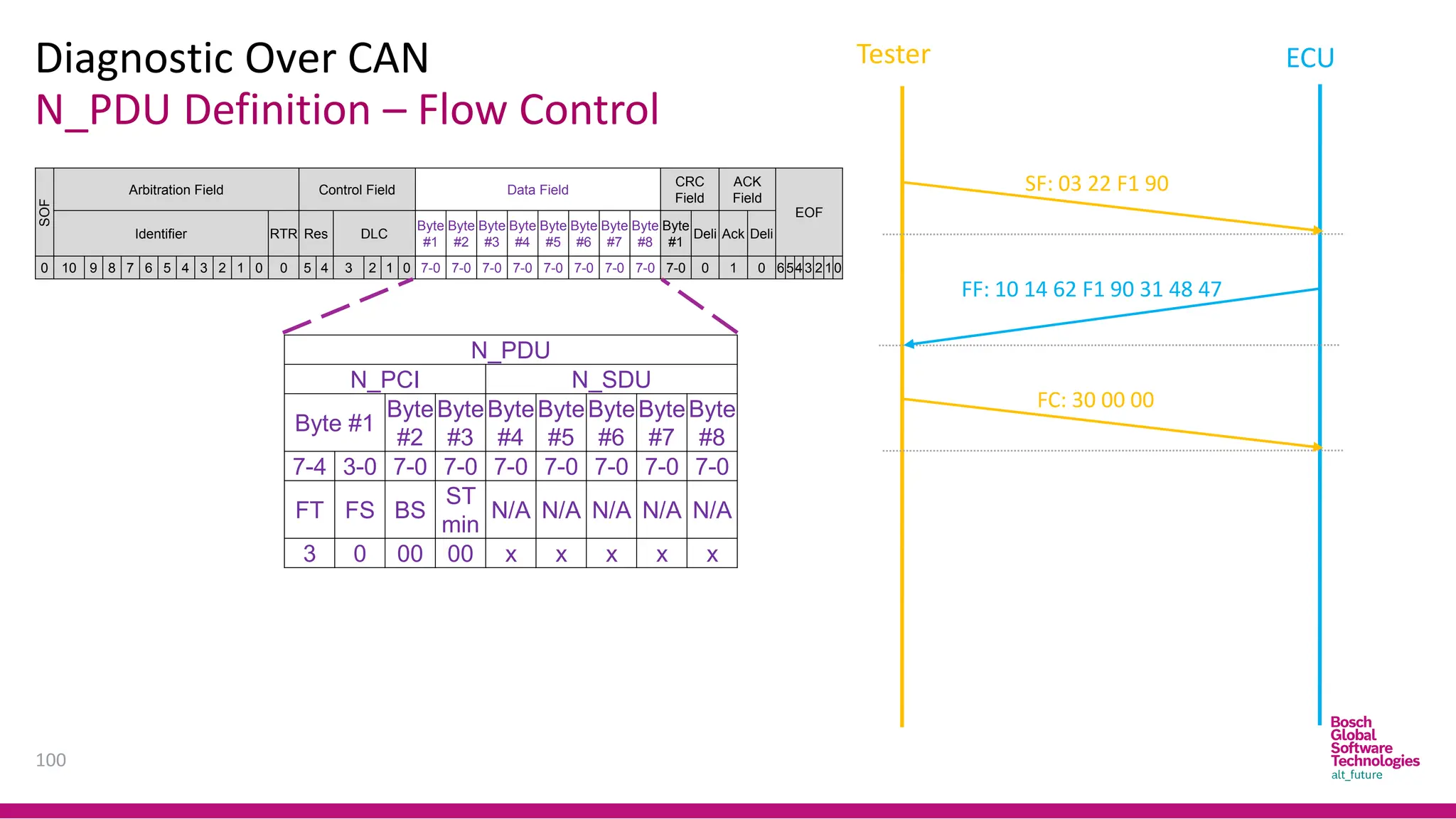
N_PDU Definition –Flow Control
Diagnostic Over CAN
100
SOF
Arbitration Field Control Field Data Field
CRC
Field
ACK
Field
EOF
Identifier RTR Res DLC
Byte
#1
Byte
#2
Byte
#3
Byte
#4
Byte
#5
Byte
#6
Byte
#7
Byte
#8
Byte
#1
Deli Ack Deli
0 10 9 8 7 6 5 4 3 2 1 0 0 5 4 3 2 1 0 7-0 7-0 7-0 7-0 7-0 7-0 7-0 7-0 7-0 0 1 0 6543 2 10
FF: 10 14 62 F1 90 31 48 47
SF: 03 22 F1 90
FC: 30 00 00
N_PDU
N_PCI N_SDU
Byte #1
Byte
#2
Byte
#3
Byte
#4
Byte
#5
Byte
#6
Byte
#7
Byte
#8
7-4 3-0 7-0 7-0 7-0 7-0 7-0 7-0 7-0
FT FS BS
ST
min
N/A N/A N/A N/A N/A
3 0 00 00 x x x x x
Tester ECU
101.
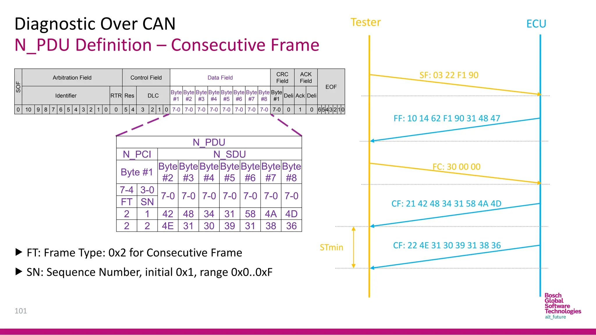
N_PDU Definition –Consecutive Frame
Diagnostic Over CAN
101
SOF
Arbitration Field Control Field Data Field
CRC
Field
ACK
Field
EOF
Identifier RTR Res DLC
Byte
#1
Byte
#2
Byte
#3
Byte
#4
Byte
#5
Byte
#6
Byte
#7
Byte
#8
Byte
#1
Deli Ack Deli
0 10 9 8 7 6 5 4 3 2 1 0 0 5 4 3 2 1 0 7-0 7-0 7-0 7-0 7-0 7-0 7-0 7-0 7-0 0 1 0 6543 2 10
FF: 10 14 62 F1 90 31 48 47
SF: 03 22 F1 90
STmin
N_PDU
N_PCI N_SDU
Byte #1
Byte
#2
Byte
#3
Byte
#4
Byte
#5
Byte
#6
Byte
#7
Byte
#8
7-4 3-0
7-0 7-0 7-0 7-0 7-0 7-0 7-0
FT SN
2 1 42 48 34 31 58 4A 4D
2 2 4E 31 30 39 31 38 36
FT: Frame Type: 0x2 for Consecutive Frame
SN: Sequence Number, initial 0x1, range 0x0..0xF
CF: 21 42 48 34 31 58 4A 4D
CF: 22 4E 31 30 39 31 38 36
FC: 30 00 00
Tester ECU
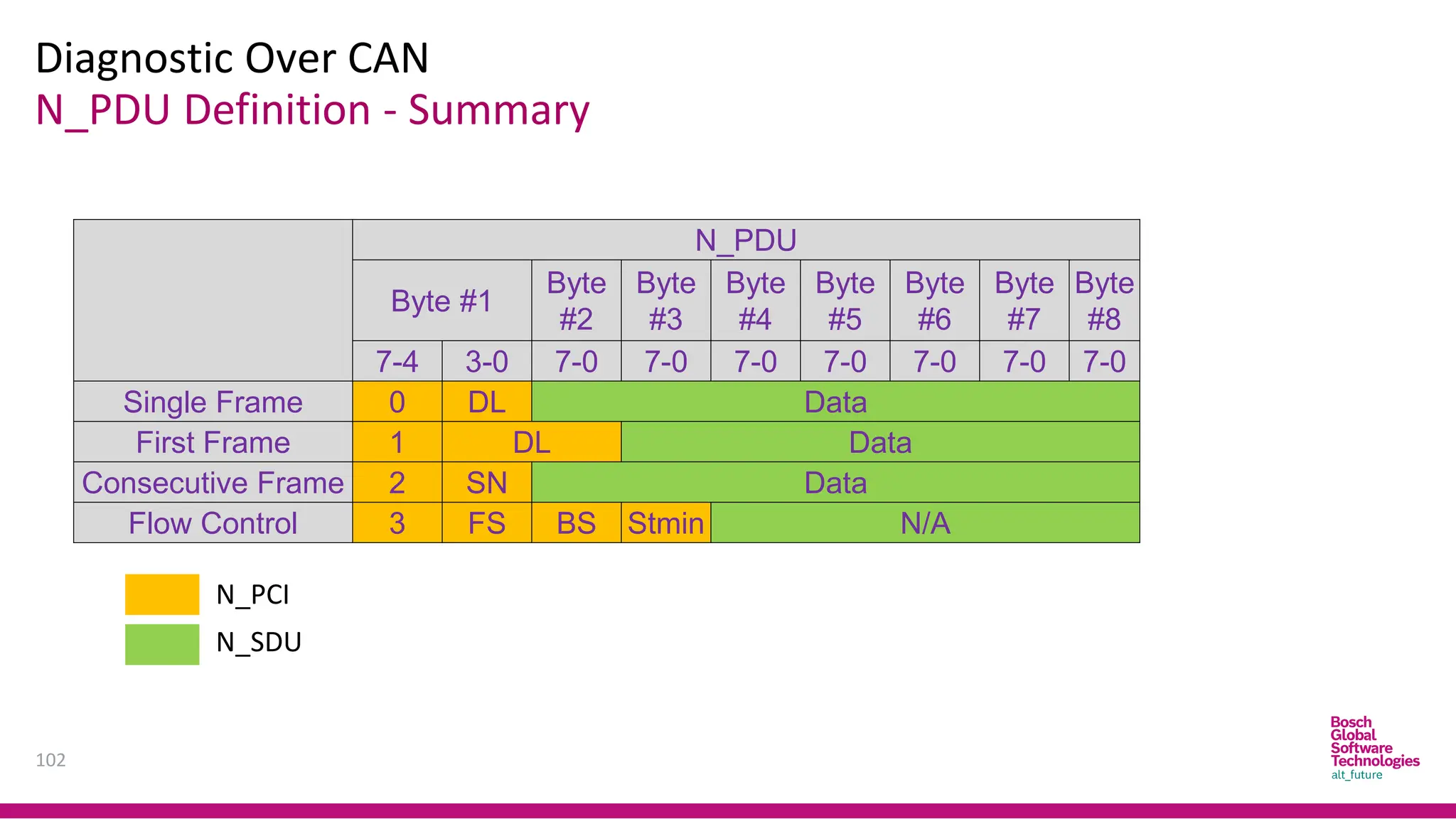
102.
N_PDU Definition -Summary
Diagnostic Over CAN
102
N_PDU
Byte #1
Byte
#2
Byte
#3
Byte
#4
Byte
#5
Byte
#6
Byte
#7
Byte
#8
7-4 3-0 7-0 7-0 7-0 7-0 7-0 7-0 7-0
Single Frame 0 DL Data
First Frame 1 DL Data
Consecutive Frame 2 SN Data
Flow Control 3 FS BS Stmin N/A
N_PCI
N_SDU
103.
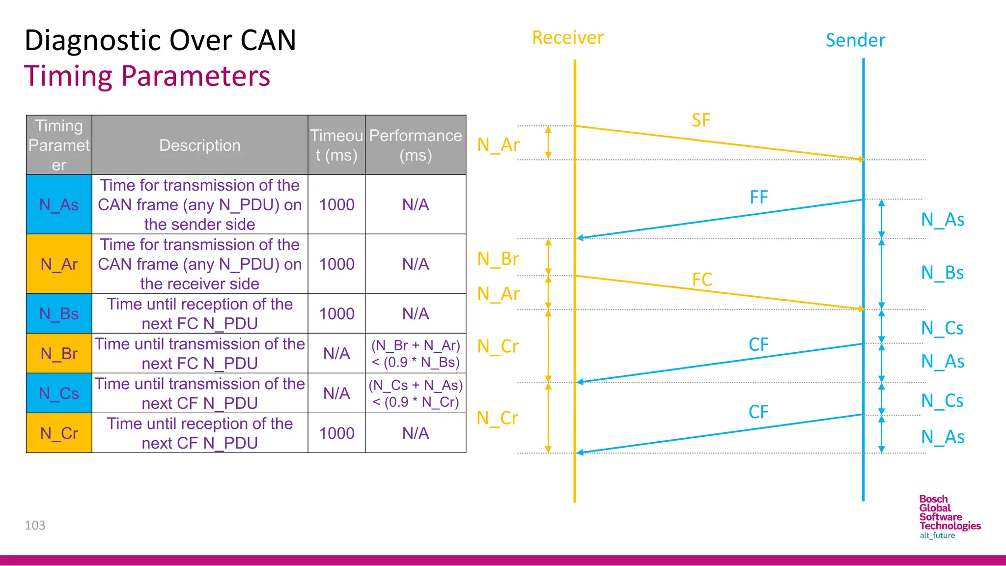
Timing Parameters
Diagnostic OverCAN
103
Receiver Sender
N_Ar
N_Ar
N_Br
N_Cr
N_Cr
N_As
N_As
N_As
N_Cs
N_Cs
N_Bs
Timing
Paramet
er
Description
Timeou
t (ms)
Performance
(ms)
N_As
Time for transmission of the
CAN frame (any N_PDU) on
the sender side
1000 N/A
N_Ar
Time for transmission of the
CAN frame (any N_PDU) on
the receiver side
1000 N/A
N_Bs
Time until reception of the
next FC N_PDU
1000 N/A
N_Br
Time until transmission of the
next FC N_PDU
N/A
(N_Br + N_Ar)
< (0.9 * N_Bs)
N_Cs
Time until transmission of the
next CF N_PDU
N/A
(N_Cs + N_As)
< (0.9 * N_Cr)
N_Cr
Time until reception of the
next CF N_PDU
1000 N/A
SF
FC
FF
CF
CF


![Definitions
Diagnosis – How?[1]
39
To do Diagnostic, Technician have to know how to use Diagnostic Tools and
Equipment.
Tool and Equipment could be classified into:
Basic Equipment: such as Multi-meter
Tracing Tool: like Oscilloscope
Scanner/Fault Code Readers and Analyzers.](https://image.slidesharecdn.com/canprotocol1-250908035050-afcb1812/75/Can-Protocol-1-bosch-embedded-academy-pdf-39-2048.jpg)
![Definitions
Diagnosis – How?[2]
40
The Equipment shall help technician indicate where is fault occurs in systems.
In the other word, In Vehicle, Systems should have ability to provide
information in case request.
This is the motivation of On-board diagnostics (OBD).
On-board diagnostics (OBD) is a generic term referring to a vehicle’s self-
diagnostic and reporting system. OBD systems give the vehicle owner or a
technician access to information for various vehicle systems.
OBD system illuminates a warning lamp known as the malfunction indicator
lamp (MIL) or malfunction indicator (MI) on the instrument cluster.](https://image.slidesharecdn.com/canprotocol1-250908035050-afcb1812/75/Can-Protocol-1-bosch-embedded-academy-pdf-40-2048.jpg)
![Definitions
Diagnosis – How?[3]
41
When the fault occurs, the system stores a diagnostic trouble code (DTC), also
store important information of the vehicle when the fault was set.
A service technician is able to connect a diagnostic scan tool or a code reader
that will communicate with the system and retrieve this information.
As vehicles and their systems become more complex, the functionality of OBD
is being extended to cover vehicle systems and components that do not have
anything to do with vehicle emissions control: Vehicle body, chassis and
accessories
OBD systems use a standardized communications port to provide data
The Communication between Diagnostic Equipment and ECUs through Vehicle
Special Interface for Diagnosis purpose is called Diagnostic Communication.](https://image.slidesharecdn.com/canprotocol1-250908035050-afcb1812/75/Can-Protocol-1-bosch-embedded-academy-pdf-41-2048.jpg)


![1. SIH2025-IDEA-Presentation-Format[1].pptx](https://cdn.slidesharecdn.com/ss_thumbnails/1-251204091914-b1bb69d5-thumbnail.jpg?width=640&height=640&fit=bounds)


