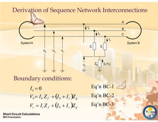
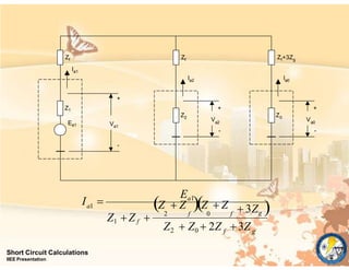
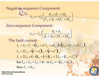
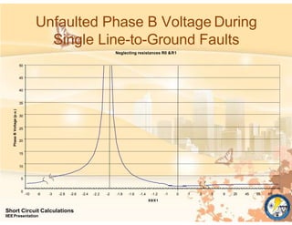
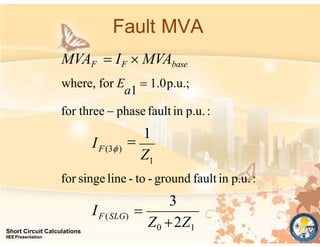
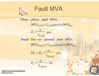
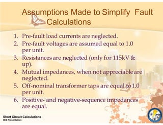
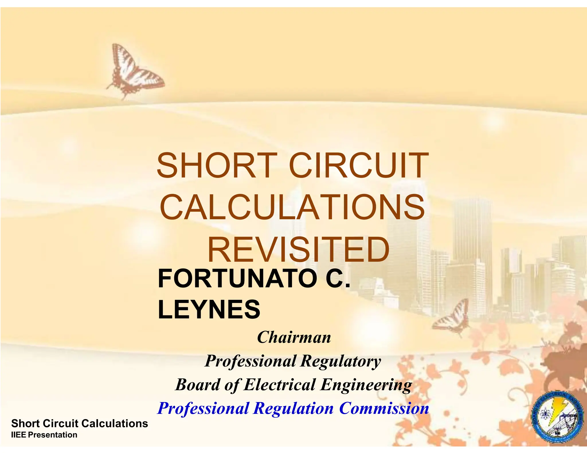
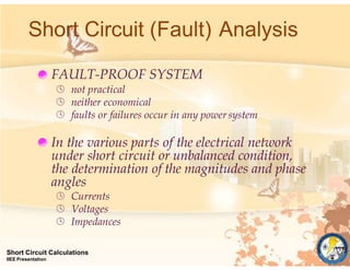
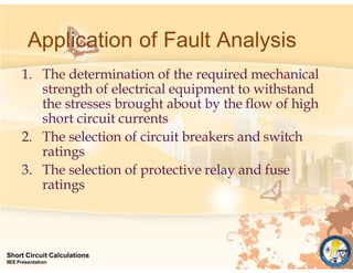
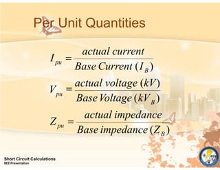
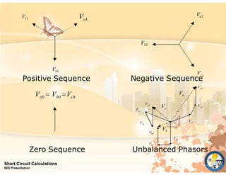
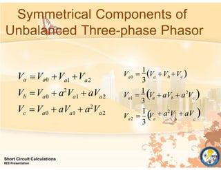
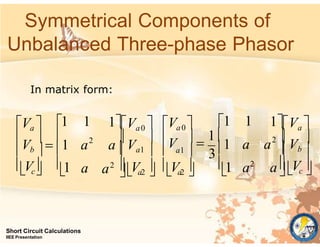
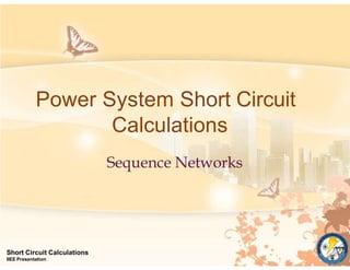
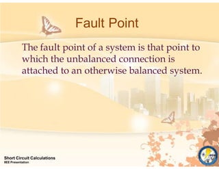
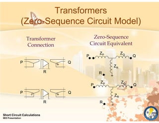
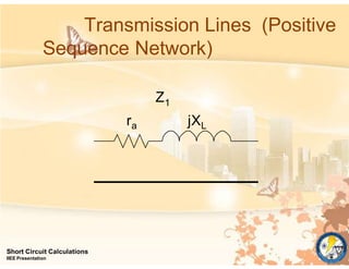
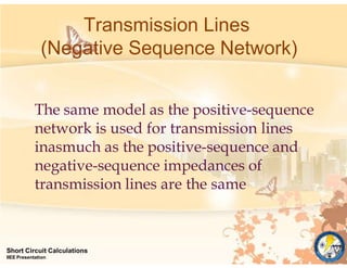
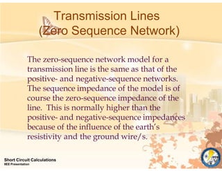
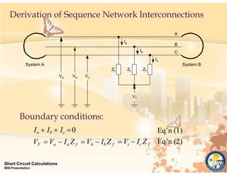
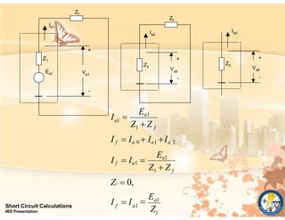
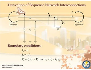
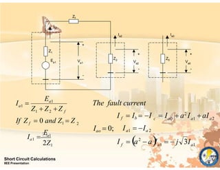
This document discusses short circuit calculations and fault analysis in power systems. It begins by explaining that while fault-proof systems are not practical, determining currents, voltages, and impedances during faults is important for several applications including equipment ratings, protective device coordination, and stability studies. The document then covers per-unit calculations, symmetrical components analysis using positive, negative, and zero sequence networks, and modeling components like generators, transformers and transmission lines in these networks. Various types of faults are classified including balanced, unbalanced, shunt and series faults. The derivation of connecting these sequence networks for fault analysis is also presented.
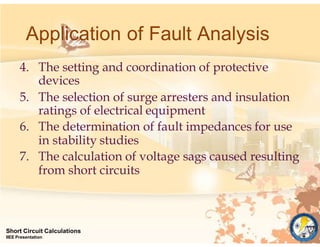
![Changing the Base of Per Unit
Quantities
pu[new]
B[new]
Short Circuit Calculations
IIEE Presentation
[new]
[new]
B[new]
[old]
pu[old]
[old]
pu[old]
Z
Z
base kVA
basekV
Z
base kVA[old]
base kVA[old]
Z
Z()
2
1000
Z base kV 2
1000
Z()
base kV 2
1000
actual impedance, Z()](https://image.slidesharecdn.com/969-240415232559-13e629ab/85/SHORT-CIRCUIT-CALCULATIONS-REVISITED-pptx-9-320.jpg)
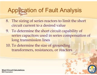
![Changing the Base of Per Unit
Quantities
B[new]
Short Circuit Calculations
IIEE Presentation
pu[new]
[new]
[new]
B[new]
[old]
pu[old ]
[old ]
pu[old]
Z
Z
base kVA
basekV
Z
base kVA[old]
base kVA[old]
Z
Z()
2
1000
Z base kV 2
1000
Z()
base kV 2
1000
actual impedance, Z()](https://image.slidesharecdn.com/969-240415232559-13e629ab/85/SHORT-CIRCUIT-CALCULATIONS-REVISITED-pptx-10-320.jpg)
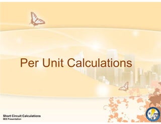
![1
Short Circuit Calculations
IIEE Presentation
1
1
1
2
f [3]
f [3]
f
3
I
I
Z
I
2Z
3Ea1
Ea1
Ea1
3 Ea1
2 Z
I f j
if Z f 0
f
2Z Z
I j 3
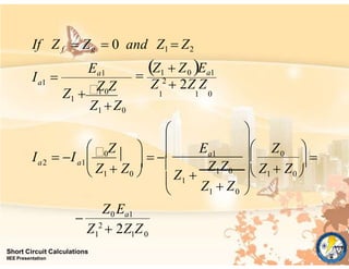
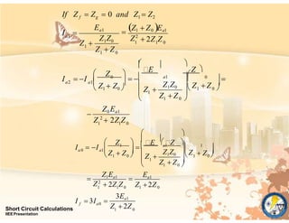
thus, with Z1 Z2
f [LL]](https://image.slidesharecdn.com/969-240415232559-13e629ab/85/SHORT-CIRCUIT-CALCULATIONS-REVISITED-pptx-56-320.jpg)