Downloaded 195 times
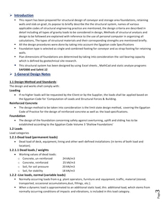
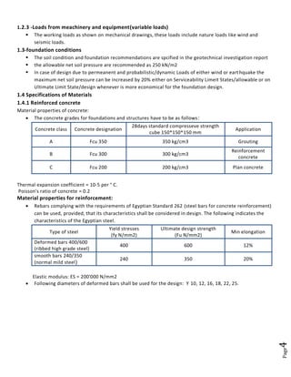
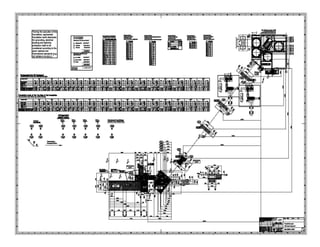
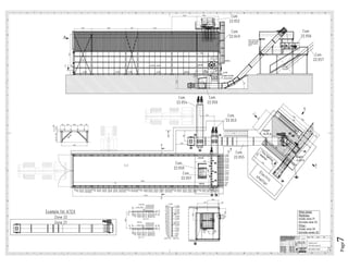
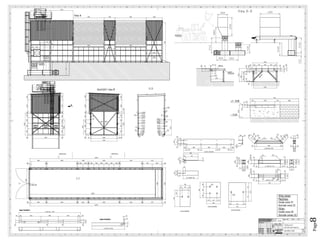
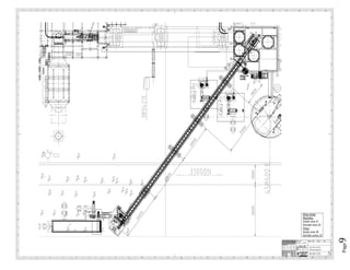
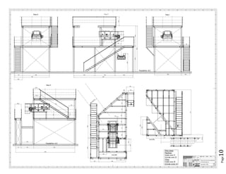
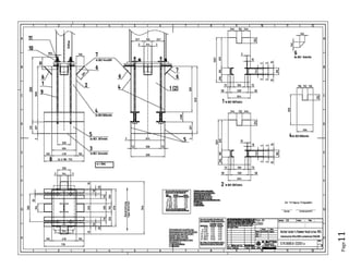
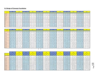
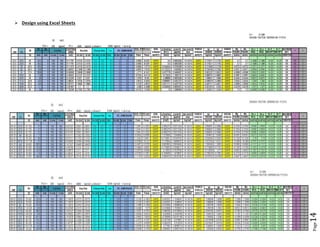
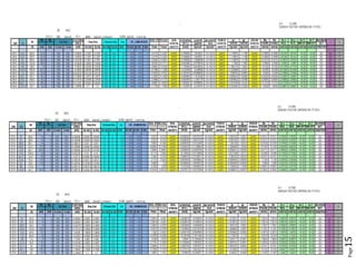
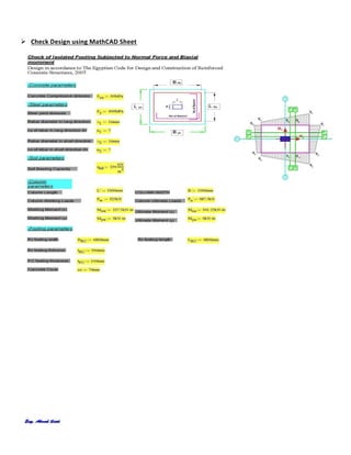
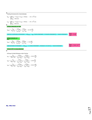
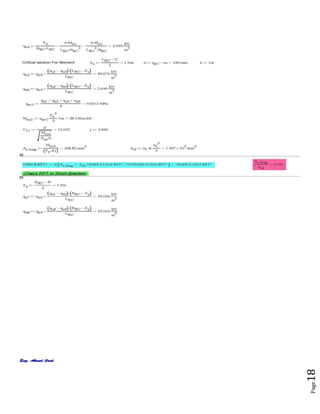
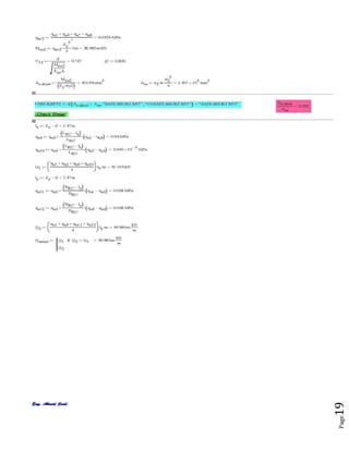
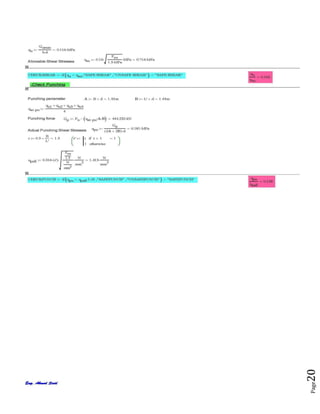
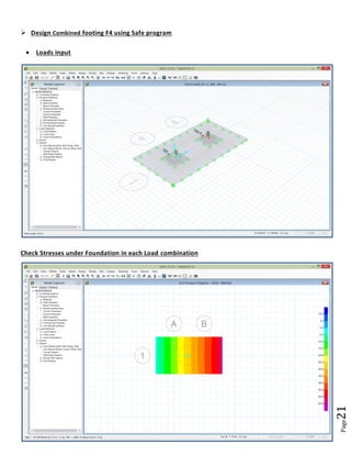
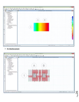
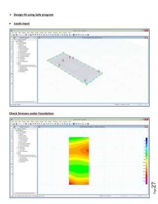
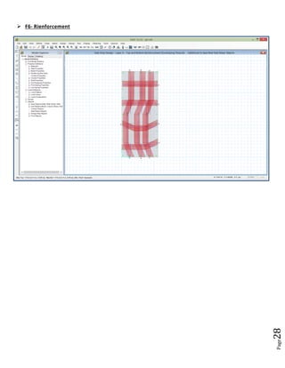
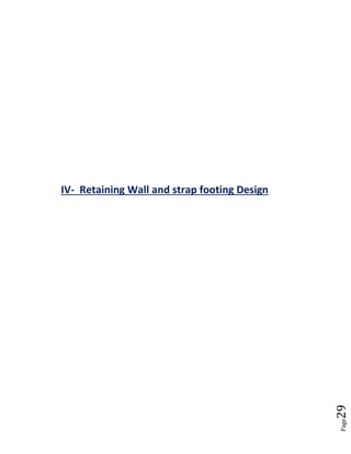
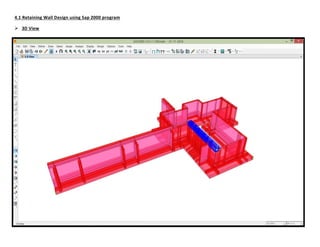
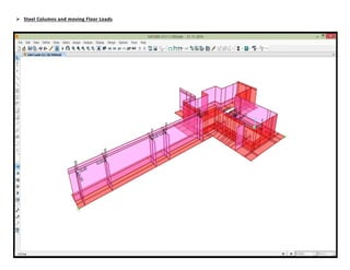
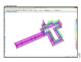
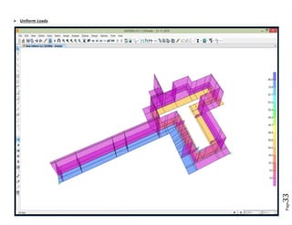
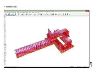
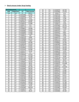
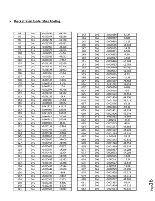
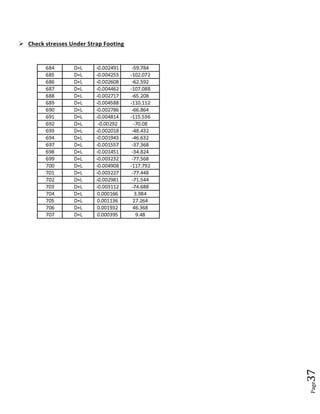
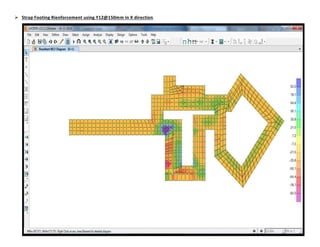
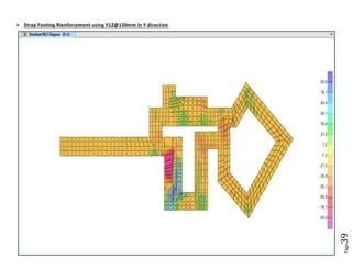
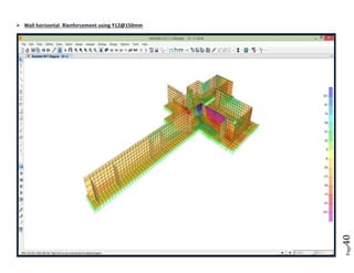
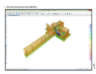
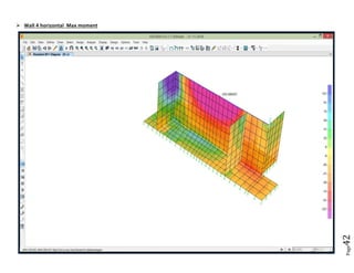
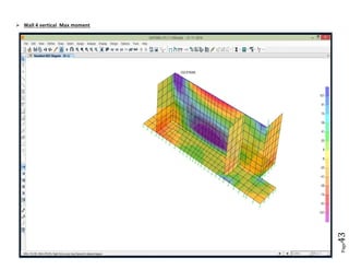
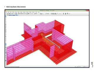
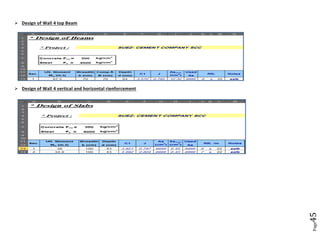

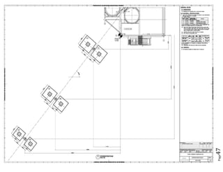
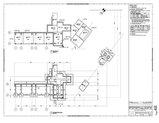
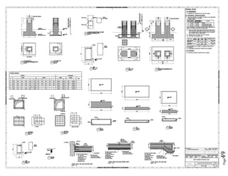
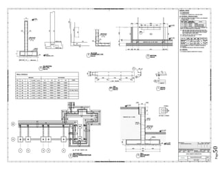

The document provides design details for foundations and retaining walls for a conveyor system and storage area at Suez Cement Company. General design notes specify the design standards, loads, foundation conditions, and material specifications to be used. Foundations are designed for individual conveyor components using Excel, MathCAD, and SAP2000 for analysis and reinforcement detailing. Retaining wall and strap footing design is conducted in SAP2000, applying earth pressures, uniform loads, and determining moments and reinforcement. Design drawings including plans, sections and reinforcement details are provided.