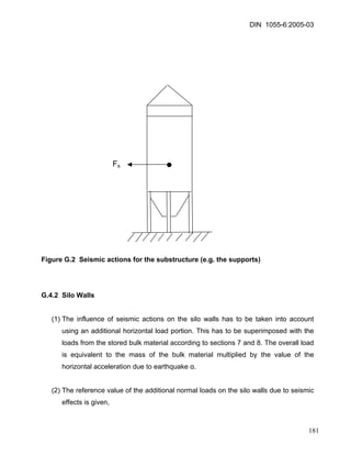
This document outlines standards and procedures for determining loads on silo and tank structures from stored bulk materials. It includes definitions of terms and symbols, methods for calculating fill and discharge loads on silo walls, loads in silo hoppers and bottoms, and loads on tanks. Measurement procedures are provided for determining important bulk material parameters needed for load calculations, such as density, wall friction, internal friction, and elasticity. Annexes provide additional guidance, standards, and alternative calculation methods.

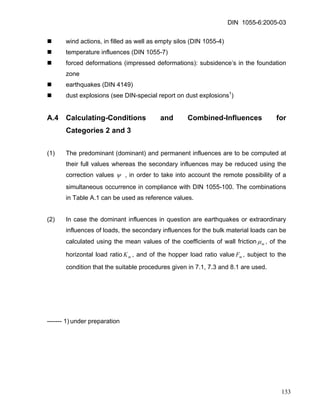
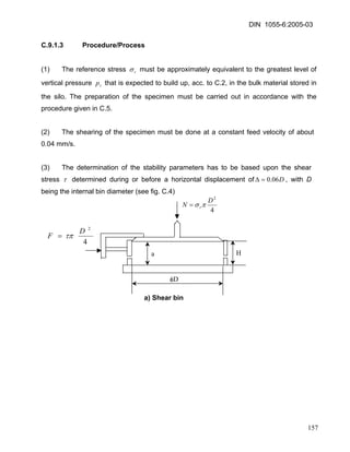
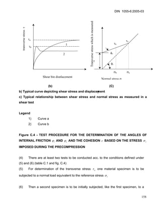
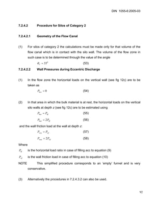
![DIN 1055-6:2005-03
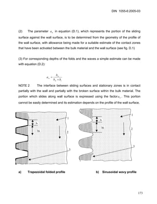
]
2
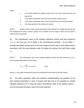
1
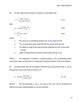
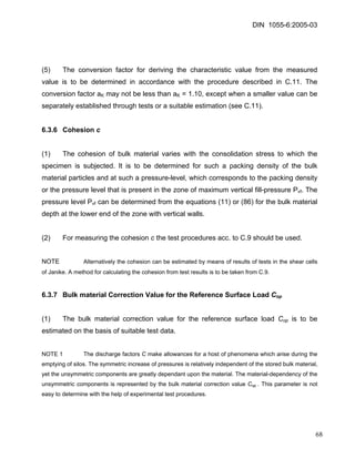
2
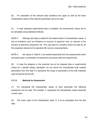
1
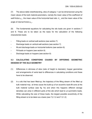
5
4
5
3
1
4
5
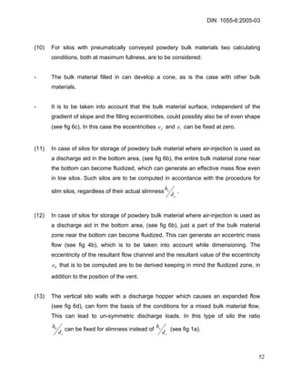
1
2
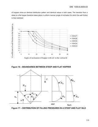
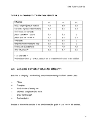
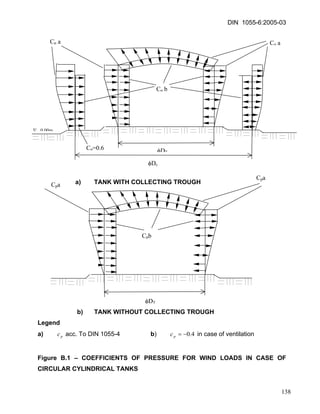
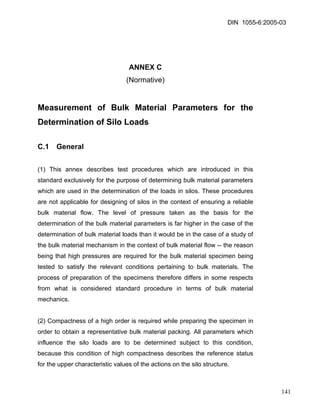
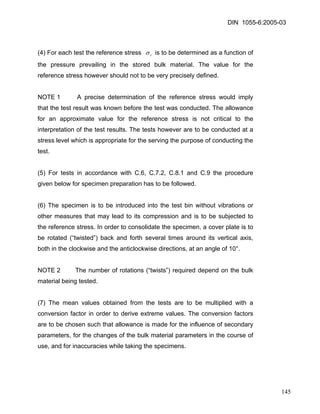
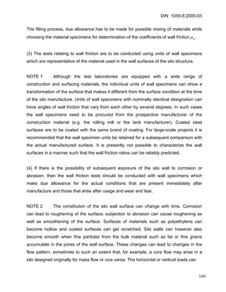
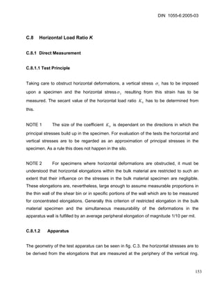
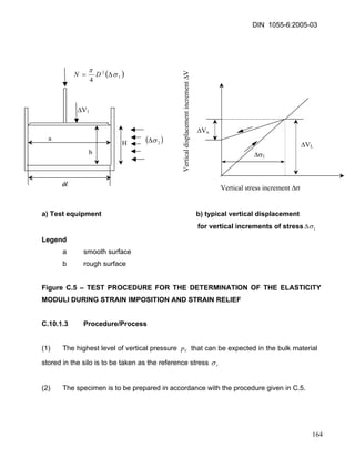
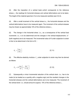
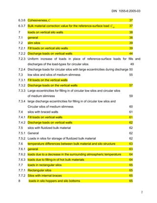
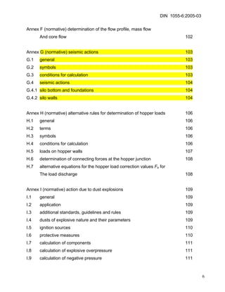
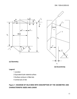
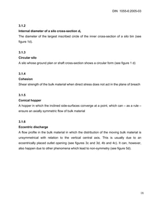
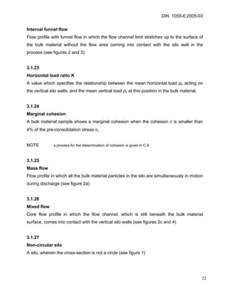
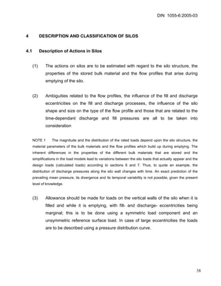
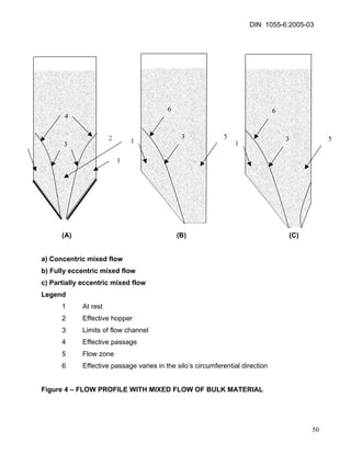
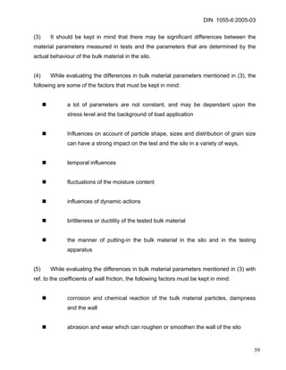
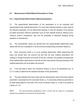
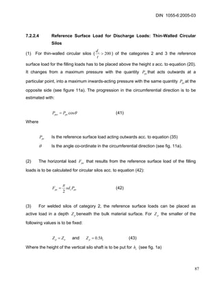
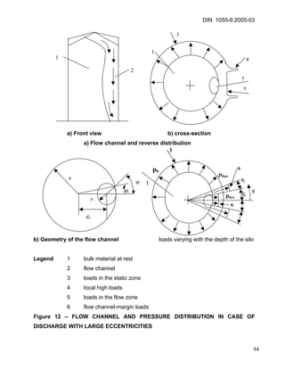
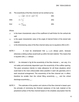
a) Braced wall silo b) Low silo c) Slim silo d) Very slim silo
Legend
1 Bulk material at rest
2 Flow channel limits
3 Effective hopper
4 Effective passage
5 Flow
Figure 5 – EFFECTS OF THE SLIMNESS (RATIO OF HEIGHT TO DIAMETER) ON THE MIXED FLOW OF THE BULK MATERIAL AND THE FUNNEL FLOW
51](https://image.slidesharecdn.com/51989151-din-1055-6-2005silos-141212153608-conversion-gate01/85/51989151-din-1055-6-2005-silos-51-320.jpg)

![DIN 1055-6:2005-03
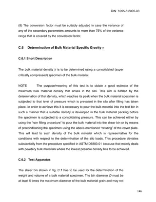
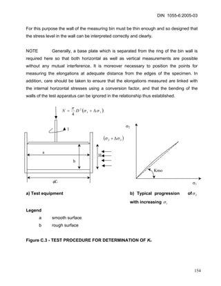
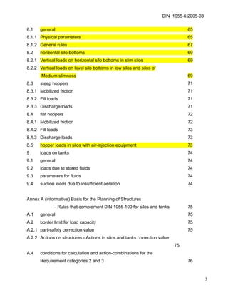
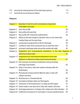
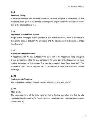
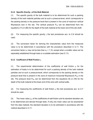
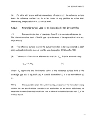
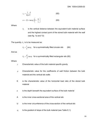
K The characteristic value of the horizontal load ratio
z The depth of the silo material beneath the equivalent surface of the bulk material
A The inner cross-sectional area of the silo
U The circumference of the inner cross-sectional area of the silo
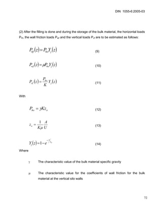
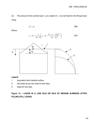
(3) For the status after the filling is done, the resultant characteristic value of the wall friction loads Pwf that have been added-up up till depth z – with the force per unit of length in the direction of the circumference e.g. [kN/M] – is calculated using:
(15) ()()[]zYzzPdzzPPjohozwfwf−==∫μ 0
(4) For determining the characteristic values for the required bulk material parameters (specific gravity (γ), correction value for wall friction μ and horizontal load ratio K), the values given in 6.2 and 6.3 are to be used.
7.2.1.2 Reference Surface Load for Filling Loads: General
Requirements
(1) For making an allowance for unplanned unsymmetrical loads due to eccentricities and imperfections during the filling of the silos, reference surface loads or other suitable load arrangements are to be placed.
(2) For silos of category 1 the reference surface load can be ignored for the filling loads.
73](https://image.slidesharecdn.com/51989151-din-1055-6-2005silos-141212153608-conversion-gate01/85/51989151-din-1055-6-2005-silos-73-320.jpg)
![DIN 1055-6:2005-03
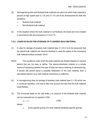
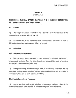
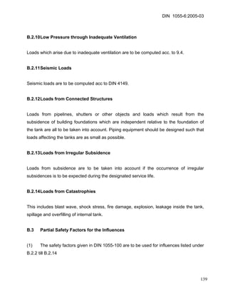
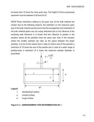
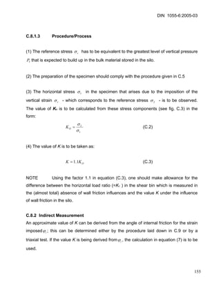
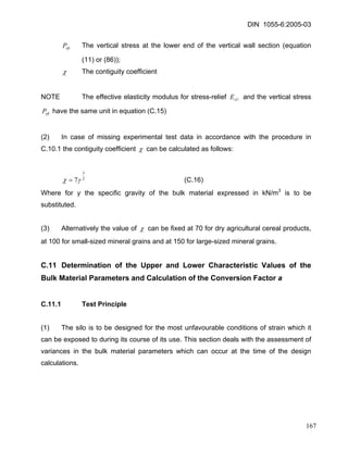
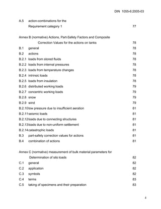
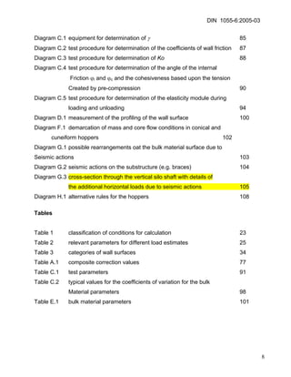
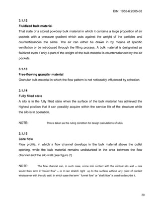
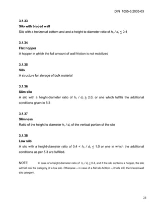
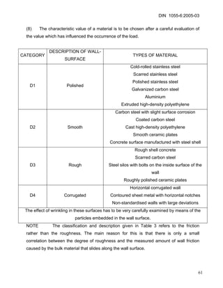
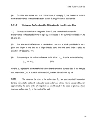
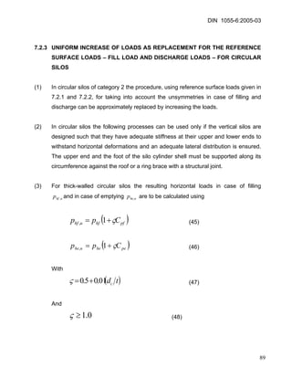
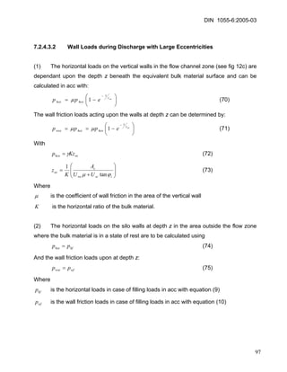
Ppe,nc
Ppf,nc
Ppe,nc
Ppf,nc
Ppe,nc
]
ppf,nc
S
a
hc
S
a
hc
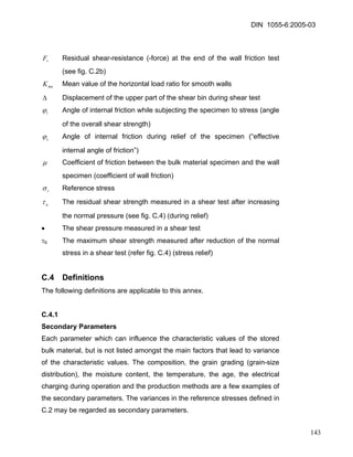
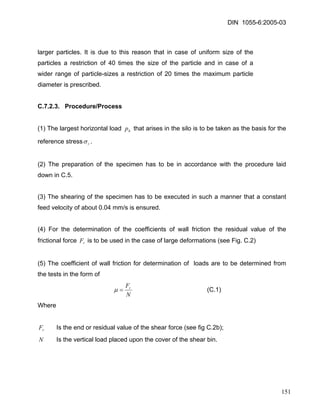
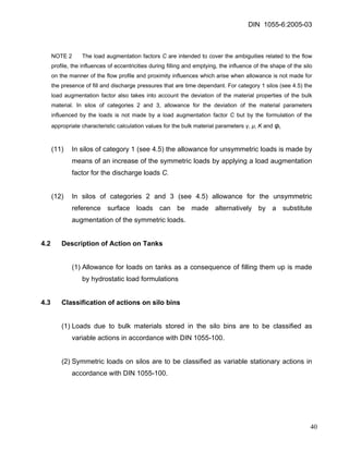
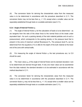
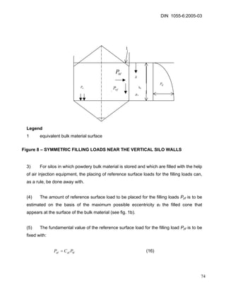
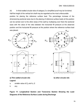
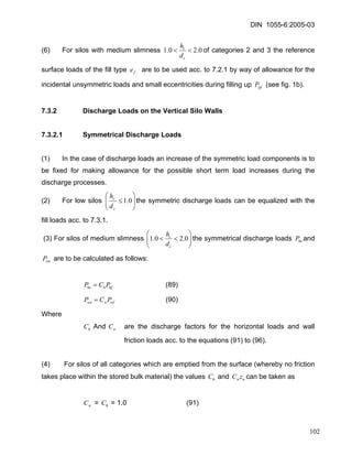
Legend
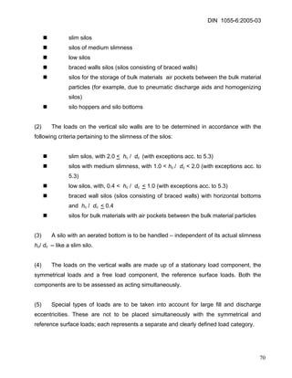
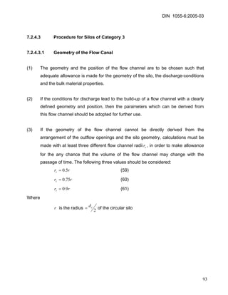
a smaller value of zo and hc/2
b as per choice
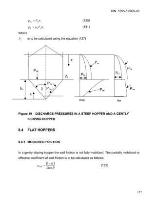
Figure 10 – LONGITUDNAL SECTION AND TRANSVERSE SECTION SHOWING THE LOAD DIAGRAMS OF THE REFERENCE SURFACE LOADS FOR NON-CIRCULAR SILOS
77](https://image.slidesharecdn.com/51989151-din-1055-6-2005silos-141212153608-conversion-gate01/85/51989151-din-1055-6-2005-silos-77-320.jpg)
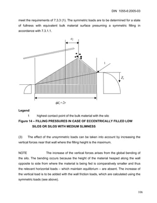
![DIN 1055-6:2005-03
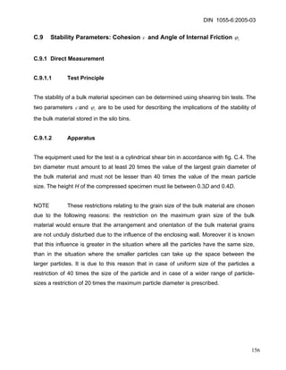
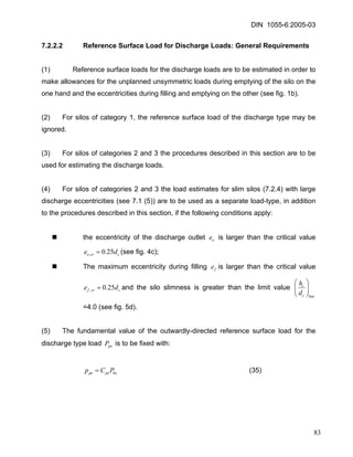
(5) For slim silos of category 1, for which the mean values of the bulk material parameters Kand μare used for load determination, the following values are to be taken as discharge factors:
opchCdeC⎟⎠⎞ ⎜⎝⎛ ++=4.015.115.1 (31)
⎟⎠⎞ ⎜⎝⎛ += cwdeC4.014.1 (32)
()ofeee,max= (33)
Where
fe is the maximum eccentricity of the filled cone which appears during filling at the bulk material surface (see fig 1b);
oe is the eccentricity of the midpoint of the discharge outlet;
opC is the bulk material correction value for the reference surface load (see Table E.1)
(6) For the discharge type load the resultant characteristic value of the wall friction loads which have been added-up up to the depth z – with the force per unit length for the circumferential direction of the wall, e.g. [kN/m] – is derived from: weP
(34) ()()[∫−== zjohowwewezYzzPCdzzpp0 μ ]
82](https://image.slidesharecdn.com/51989151-din-1055-6-2005silos-141212153608-conversion-gate01/85/51989151-din-1055-6-2005-silos-82-320.jpg)
![DIN 1055-6:2005-03
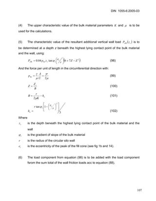
(4) For the fill load the resultant characteristic value of the wall friction loads which have been added up to a bulk material depth z – with the force per unit length in the circumferential direction of the wall, e.g. [kN/m] – is calculated using: wfP
()()vhozwfwfzzPdzzPP−==∫μ 0 (88)
With acc. to equation (87) vz
7.3.1.2 Reference Surface Load for Fill Loads
(1) The fill type of reference surface loads are to be fixed at each point in the vertical projection of the silo as allowance for unplanned loads and small filling eccentricities (see figure 1b) pfP
(2) Details for determining the form, the position and the amount of the reference surface load for fill loads are to be taken from the regulations in 7.2.1
(3) The reference surface load consists of only one horizontally acting load component. There are no additional friction loads to be taken into account as a consequence of this horizontal component.
(4) For low silos 0.1≤ ccdhof all categories, the fill type of reference surface loads need not be taken into account 0=pfC
(5) For silos with medium slimness 0.20.1<< ccdhof category 1, the fill type of reference surface loads need not be taken into account 0=pfC
101](https://image.slidesharecdn.com/51989151-din-1055-6-2005silos-141212153608-conversion-gate01/85/51989151-din-1055-6-2005-silos-101-320.jpg)
![DIN 1055-6:2005-03
(7) For discharge load the resultant characteristic value of the wall friction loads added up to depth z - with the force per unit length in the circumferential direction of the wall, e.g. [kN/m] to be derived from: weP
(97a) ()()vhowzwewezzPCdzzPP−==∫μ 0
With acc. to equation (87) vz
7.3.2.2 Reference Surface Load for Discharge Loads
(1) The reference surface loads in case of discharge are to be fixed taking into account unplanned loads and small filling eccentricities (see fig. 1b). peP
(2) Details of the form, positioning and quantity of the discharge type reference surface load are to be taken from the regulations in 7.2.2.
(3) For low silos ⎟⎟⎠ ⎞ ⎜⎜⎝ ⎛ ≤0.1ccdhof all categories, the formulation of a reference surface load of the discharge type can be ignored (i.e.0=peC) in case of an eccentricity during emptying which is smaller than the critical value of oeccrode1.0,=
(4) For low silos and silos of medium slimness ⎟⎟⎠ ⎞ ⎜⎜⎝ ⎛ <0.2ccdh of category 1, the formulation of a reference surface load of the discharge type can be ignored (i.e0=peC).
(5) For low silos ⎟⎟⎠ ⎞ ⎜⎜⎝ ⎛ ≤0.1ccdhof category 2 and an eccentricity during emptying which is greater than the critical value of oeccrode1.0,=, the formulations in 7.3.2.3 can be used.
(6) For silos with medium slimness ⎟⎟⎠ ⎞ ⎜⎜⎝ ⎛ <<0.20.1ccdhof category 2, the formulations in 7.3.2.3 can be used.
104](https://image.slidesharecdn.com/51989151-din-1055-6-2005silos-141212153608-conversion-gate01/85/51989151-din-1055-6-2005-silos-104-320.jpg)