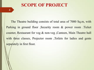
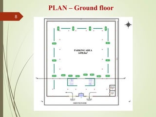
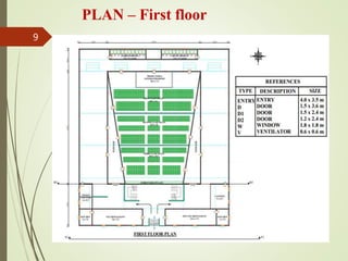
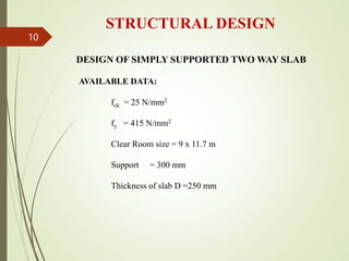
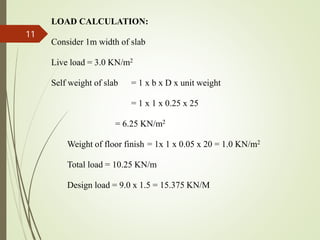
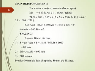
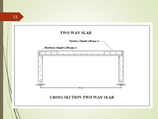
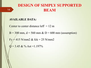
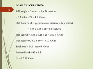
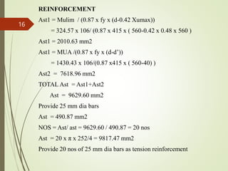
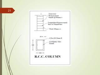
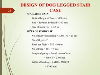
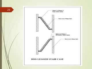
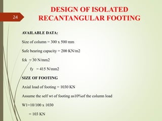
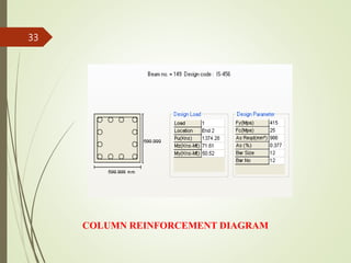
PLANNING, DESIGNING AND
ANALYSIS OF THEATRE
BUILDING
1
INTRODUCTION
Traditionally a movie Theatre, like a stage Theatre, consists of a
single auditorium with rows of comfortable seats, as well as a foyer
area containing a box office for buying tickets, a counter and/or
self-service facilities for buying snacks and drinks, and washrooms.
Stage Theatres are sometimes converted into movie Theatres by
placing a screen in front of the stage and adding a projector; this
conversion may be permanent.
2
OBJECTIVES OF THE PROJECT
 To plan the medical shop as per the requirements by
using software Auto CAD.
 To study and practice the analysis of a building using
STAAD.Pro software.
 To learn the design methodology of various building
components.
 To draw the reinforcement detailing of various
components.
3
SCOPE OF PROJECT
The Theatre building consists of total area of 7000 Sq.m, with
Parking in ground floor ,Security room & power room .Ticket
counter, Restaurant for veg & non-veg ,Canteen, Main Theatre hall
with three classes, Projector room ,Toilets for ladies and gents
separately in first floor.
4
BRIEF METHODOLOGY
We prepare our project plan with AUTO CAD software. The
analysis and the designing of structure such as slab, beam, column
and footing is carried out by limit state method with the IS 456: 2000
Code book specification and also using STAAD.Pro software. The
Center line method of estimation is carried out for calculating the
quantity and the rates that are adapted for the quantities from the
P.W.D current Schedule of rates.
5
SPECIFICATIONS
Total area : 7000 Sq.m
Type of the structure : Framed with RCC footing.
Grade of concrete : M25
Grade of steel : Fe415
The basement filled up with clean sand to a depth of 450 mm
and it should be compacted with water as per standard
specifications.
6
Super structure shall be of Ist class brickwork with 1:
6 cement mortar. The height of all walls will be 7000 mm
above floor level. The height of parapet wall is 3’ with 9”
thickness all around.
Main wall thickness : 9”
Partition wall thickness : 4.5”
Thickness of slab : 5”
7
PLAN – Ground floor
8
PLAN – First floor
9
STRUCTURAL DESIGN
DESIGN OF SIMPLY SUPPORTED TWO WAY SLAB
AVAILABLE DATA:
fck = 25 N/mm2
fy = 415 N/mm2
Clear Room size = 9 x 11.7 m
Support = 300 mm
Thickness of slab D =250 mm
10
LOAD CALCULATION:
Consider 1m width of slab
Live load = 3.0 KN/m2
Self weight of slab = 1 x b x D x unit weight
= 1 x 1 x 0.25 x 25
= 6.25 KN/m2
Weight of floor finish = 1x 1 x 0.05 x 20 = 1.0 KN/m2
Total load = 10.25 KN/m
Design load = 9.0 x 1.5 = 15.375 KN/M
11
MAIN REINFORCEMENT:
For shorter span (max mom in shorter span)
Mx = 0.87 fy Ast d ( 1- fyAst / fckbd)
74.66 x 106 = 0.87 x 415 x Ast x 230 ( 1- 415 x Ast /
25 x 1000 x 230 )
5.99 Ast2 – 83.04 x 10³Ast + 74.66 x 106 = 0
Ast min = 966.46 mm2
SPACING:
Assume 10 mm dia bars
1) S = ast / Ast x b = 78.54 / 966.46 x 1000
= 80 mm
2) 3d = 3 x 230 = 690 mm
3) 300 mm c/c
Provide 10 mm dia bars @ spacing 80 mm c/c distance.
12
13
DESIGN OF SIMPLY SUPPORTED
BEAM
AVAILABLE DATA:
Center to center distance leff = 12 m
B = 300 mm, d = 560 mm & D = 600 mm (assumption)
Fy = 415 N/mm2 & fck = 25 N/mm2
Q = 3.45 & % Ast =1.197%
14
LOAD CALCULATION:
Self weight of beam = b x D x unit wt
= 0.3 x 0.6 x 25 = 4.5 KN/m
Slab floor finish = perpendicular distance x tk x unit wt
= 5.85 x 0.05 x 20 = 5.85 KN/m
Slab self wt = 5.85 x 0.25 x 25 = 36.56 KN/m
Wall load = 0.3 x 3 x 19 = 17.10 KN/m
Total load = 64.01 say 65 KN/m
Factored load = 65 x 1.5
Fd = 97.50 KN/m
15
REINFORCEMENT
Ast1 = Mulim / (0.87 x fy x (d-0.42 Xumax))
= 324.57 x 10⁶/ (0.87 x 415 x ( 560-0.42 x 0.48 x 560 )
Ast1 = 2010.63 mm2
Ast1 = MUA /(0.87 x fy x (d-d’))
= 1430.43 x 106/(0.87 x415 x ( 560-40) )
Ast2 = 7618.96 mm2
TOTAL Ast = Ast1+Ast2
Ast = 9629.60 mm2
Provide 25 mm dia bars
Ast = 490.87 mm2
NOS = Ast/ ast = 9629.60 / 490.87 = 20 nos
Ast = 20 x π x 252/4 = 9817.47 mm2
Provide 20 nos of 25 mm dia bars as tension reinforcement
16
17
DESIGN OF RECTANGULAR
COLUMN
AVAILABLE DATA:
Size of column= 300 x 500 mm
fck = 25 N/mm2
fy = 415 N/mm2
LOAD CALCULATION:
SLAB:
Wt of slab1 = L x B x D x unit wt
= 4.50 x 5.85 x 0.25 x 25 = 164.53 KN
Wt of slab ff 1 = L x B x D x unit wt
= 4.85 x 5.85 x 0.05 x 20 = 28.37 KN
Live load 1 = 4.85 x 5.85 x 3.0 = 85.11 KN
18
BEAM
Beam (1) = L x B x D x unit wt
= 4.50 x 0.3 x 0.6 x 25 = 20.25 KN
Beam (2) = 5.85 x 0.3 x 0.6 x 25 = 26.33 KN
WALL
Wall load (1) = L x B x H x unit wt
= 4.50 x 0.3 x 3 x 19 = 76.95 KN
Wall load (2) = 5.85 x 0.3 x 3 x 19 = 100 KN
COLUMN
Self weight of column = L x B x H x unit wt
= 0.3 x 0.5 x 3 x 25 = 11.25 KN
Sum of all above loads = 512.49 KN
No of floor consideration = 515 x 2 = 1030 KN
19
LONGITUDINAL REINFORCEMENT
Let assume Asc = 1% Ag
= 0.01 Ag
= 0.01 x 150 x 103
= 1500 mm2
Area of concrete Ac = Ag – 0.01 Ag = 0.99 Ag
= 0.99 x 150 x 103
= 148.50 x 10³
Pu = 0.4fck Ac + 0.67fyAsc
Pu = 0.4 x 25 x 148.50 x 103+ 0.67 x 415 x 1500
Pu = 1902.07 KN
Say Pu = 1900 KN > 1545 KN
20
21
DESIGN OF DOG LEGGED STAIR
CASE
AVAILABLE DATA
Vertical height of floor = 3000 mm
Rise = 150 mm & thread = 300 mm
Size of room = 6.1 x 7.6 m
SIZES OF STAIRCASE
No of riser = height/rise = 3000/150 = 20 nos
No of flight = 2
Riser per flight = 20/2 =10 nos
No of tread = 10-1 = 9 nos
Length of going = thread x nos of tread
= 300 x 9 = 2700 mm
Width of landing = ( 6100 - 2700 )/2
= 1700 mm
22
23
DESIGN OF ISOLATED
RECANTANGULAR FOOTING
AVAILABLE DATA:
Size of column = 300 x 500 mm
Safe bearing capacity = 200 KN/m2
fck = 30 N/mm2
fy = 415 N/mm2
SIZE OF FOOTING
Axial load of footing = 1030 KN
Assume the self wt of footing as10%of the column load
W1=10/100 x 1030
= 103 KN
24
Total load on soil =1030 + 103 = 1133 KN
Area of footing required = total load /sbc
= 1140 / 200
= 5.7 m2
Since it is a rectangular column
The size of rectangular footing having the side ratio of L/B = 1.5
B x L = 5.7 m2
B x (1.5B) = 5.7 m2
1.5B2 = 5.7
B= 2.0 & L= 3.0 m
Area of footing = 2.0 x 3.0 = 6 m2
25
26
STAAD.Pro Report
2D STRUCTURE
27
3D STRUCTURE
28
200
200
200
200
400
400
400
400
2 4 6 6.6
75 76
305 305
-153
3.3
Mz(kNm)
BEAM IDENTIFICATION DIAGRAM
BEAM 215 BENDING MOMENT
29
100
100
100
100
200
200
200
200
300
300
300
300
2 4 6 6.6
75 76
277
-277
Fy(kN)
0.01
0.01
0.01
0.01
0.02
0.02
0.02
0.02
2 4 6 6.6
75 76
Fx(kN)
BEAM 215 SHEAR FORCE
BEAM 215 AXIAL SHEAR FORCE
30
BEAM REINFORCEMENT DIAGRAM
31
COLUMN IDENTIFICATION DIAGRAM
500
500
500
500
1000
1000
1000
1000
1500
1500
1500
1500
1 2 3
3
1 75
1336 1374
Fx(kN)
COLUMN 149 AXIAL SHEAR FORCE
32
COLUMN REINFORCEMENT DIAGRAM
33
CONCLUSION
Elements of art and stagecraft are used to enhance the physicality,
presence and immediacy of the experience. The fastest world creates the
pressure of mind and crushes the public for their works. So the peoples
are gets an energy of mind relaxation them.
Through our project we conclude that application of software in
civil industry plays an important role in our study. In our project Theatre
Building we adopt planning in Autocad and limit state method for
analysis and design of our structure staad pro and also used grade of
concrete as M25 and grade of steel as Fe415.
Time taken for doing this project is very less due to the application
of the software. We bring extra accuracy in dimension and analysis part
through our project.
34
BIBLIOGRAPHY
TEXT BOOKS:
Structural engineering - A.P.ARULMANIKAM
Quantity surveying - N.MURALIKRRISHNAIYAH
Structural drawing - MURUGESAN
Estimate and costing - B.N.DUTTA
Principles of architecture - G.MUTHU, SHOBA, MOHAN
CODE BOOKS:
Concrete code - IS 456 – 2000
Steel code - IS 800:2007
35
Thank you…
36

Theatre building PPT.pptx

  • 1.
    PLANNING, DESIGNING AND ANALYSISOF THEATRE BUILDING 1
  • 2.
    INTRODUCTION Traditionally a movieTheatre, like a stage Theatre, consists of a single auditorium with rows of comfortable seats, as well as a foyer area containing a box office for buying tickets, a counter and/or self-service facilities for buying snacks and drinks, and washrooms. Stage Theatres are sometimes converted into movie Theatres by placing a screen in front of the stage and adding a projector; this conversion may be permanent. 2
  • 3.
    OBJECTIVES OF THEPROJECT  To plan the medical shop as per the requirements by using software Auto CAD.  To study and practice the analysis of a building using STAAD.Pro software.  To learn the design methodology of various building components.  To draw the reinforcement detailing of various components. 3
  • 4.
    SCOPE OF PROJECT TheTheatre building consists of total area of 7000 Sq.m, with Parking in ground floor ,Security room & power room .Ticket counter, Restaurant for veg & non-veg ,Canteen, Main Theatre hall with three classes, Projector room ,Toilets for ladies and gents separately in first floor. 4
  • 5.
    BRIEF METHODOLOGY We prepareour project plan with AUTO CAD software. The analysis and the designing of structure such as slab, beam, column and footing is carried out by limit state method with the IS 456: 2000 Code book specification and also using STAAD.Pro software. The Center line method of estimation is carried out for calculating the quantity and the rates that are adapted for the quantities from the P.W.D current Schedule of rates. 5
  • 6.
    SPECIFICATIONS Total area :7000 Sq.m Type of the structure : Framed with RCC footing. Grade of concrete : M25 Grade of steel : Fe415 The basement filled up with clean sand to a depth of 450 mm and it should be compacted with water as per standard specifications. 6
  • 7.
    Super structure shallbe of Ist class brickwork with 1: 6 cement mortar. The height of all walls will be 7000 mm above floor level. The height of parapet wall is 3’ with 9” thickness all around. Main wall thickness : 9” Partition wall thickness : 4.5” Thickness of slab : 5” 7
  • 8.
  • 9.
  • 10.
    STRUCTURAL DESIGN DESIGN OFSIMPLY SUPPORTED TWO WAY SLAB AVAILABLE DATA: fck = 25 N/mm2 fy = 415 N/mm2 Clear Room size = 9 x 11.7 m Support = 300 mm Thickness of slab D =250 mm 10
  • 11.
    LOAD CALCULATION: Consider 1mwidth of slab Live load = 3.0 KN/m2 Self weight of slab = 1 x b x D x unit weight = 1 x 1 x 0.25 x 25 = 6.25 KN/m2 Weight of floor finish = 1x 1 x 0.05 x 20 = 1.0 KN/m2 Total load = 10.25 KN/m Design load = 9.0 x 1.5 = 15.375 KN/M 11
  • 12.
    MAIN REINFORCEMENT: For shorterspan (max mom in shorter span) Mx = 0.87 fy Ast d ( 1- fyAst / fckbd) 74.66 x 106 = 0.87 x 415 x Ast x 230 ( 1- 415 x Ast / 25 x 1000 x 230 ) 5.99 Ast2 – 83.04 x 10³Ast + 74.66 x 106 = 0 Ast min = 966.46 mm2 SPACING: Assume 10 mm dia bars 1) S = ast / Ast x b = 78.54 / 966.46 x 1000 = 80 mm 2) 3d = 3 x 230 = 690 mm 3) 300 mm c/c Provide 10 mm dia bars @ spacing 80 mm c/c distance. 12
  • 13.
  • 14.
    DESIGN OF SIMPLYSUPPORTED BEAM AVAILABLE DATA: Center to center distance leff = 12 m B = 300 mm, d = 560 mm & D = 600 mm (assumption) Fy = 415 N/mm2 & fck = 25 N/mm2 Q = 3.45 & % Ast =1.197% 14
  • 15.
    LOAD CALCULATION: Self weightof beam = b x D x unit wt = 0.3 x 0.6 x 25 = 4.5 KN/m Slab floor finish = perpendicular distance x tk x unit wt = 5.85 x 0.05 x 20 = 5.85 KN/m Slab self wt = 5.85 x 0.25 x 25 = 36.56 KN/m Wall load = 0.3 x 3 x 19 = 17.10 KN/m Total load = 64.01 say 65 KN/m Factored load = 65 x 1.5 Fd = 97.50 KN/m 15
  • 16.
    REINFORCEMENT Ast1 = Mulim/ (0.87 x fy x (d-0.42 Xumax)) = 324.57 x 10⁶/ (0.87 x 415 x ( 560-0.42 x 0.48 x 560 ) Ast1 = 2010.63 mm2 Ast1 = MUA /(0.87 x fy x (d-d’)) = 1430.43 x 106/(0.87 x415 x ( 560-40) ) Ast2 = 7618.96 mm2 TOTAL Ast = Ast1+Ast2 Ast = 9629.60 mm2 Provide 25 mm dia bars Ast = 490.87 mm2 NOS = Ast/ ast = 9629.60 / 490.87 = 20 nos Ast = 20 x π x 252/4 = 9817.47 mm2 Provide 20 nos of 25 mm dia bars as tension reinforcement 16
  • 17.
  • 18.
    DESIGN OF RECTANGULAR COLUMN AVAILABLEDATA: Size of column= 300 x 500 mm fck = 25 N/mm2 fy = 415 N/mm2 LOAD CALCULATION: SLAB: Wt of slab1 = L x B x D x unit wt = 4.50 x 5.85 x 0.25 x 25 = 164.53 KN Wt of slab ff 1 = L x B x D x unit wt = 4.85 x 5.85 x 0.05 x 20 = 28.37 KN Live load 1 = 4.85 x 5.85 x 3.0 = 85.11 KN 18
  • 19.
    BEAM Beam (1) =L x B x D x unit wt = 4.50 x 0.3 x 0.6 x 25 = 20.25 KN Beam (2) = 5.85 x 0.3 x 0.6 x 25 = 26.33 KN WALL Wall load (1) = L x B x H x unit wt = 4.50 x 0.3 x 3 x 19 = 76.95 KN Wall load (2) = 5.85 x 0.3 x 3 x 19 = 100 KN COLUMN Self weight of column = L x B x H x unit wt = 0.3 x 0.5 x 3 x 25 = 11.25 KN Sum of all above loads = 512.49 KN No of floor consideration = 515 x 2 = 1030 KN 19
  • 20.
    LONGITUDINAL REINFORCEMENT Let assumeAsc = 1% Ag = 0.01 Ag = 0.01 x 150 x 103 = 1500 mm2 Area of concrete Ac = Ag – 0.01 Ag = 0.99 Ag = 0.99 x 150 x 103 = 148.50 x 10³ Pu = 0.4fck Ac + 0.67fyAsc Pu = 0.4 x 25 x 148.50 x 103+ 0.67 x 415 x 1500 Pu = 1902.07 KN Say Pu = 1900 KN > 1545 KN 20
  • 21.
  • 22.
    DESIGN OF DOGLEGGED STAIR CASE AVAILABLE DATA Vertical height of floor = 3000 mm Rise = 150 mm & thread = 300 mm Size of room = 6.1 x 7.6 m SIZES OF STAIRCASE No of riser = height/rise = 3000/150 = 20 nos No of flight = 2 Riser per flight = 20/2 =10 nos No of tread = 10-1 = 9 nos Length of going = thread x nos of tread = 300 x 9 = 2700 mm Width of landing = ( 6100 - 2700 )/2 = 1700 mm 22
  • 23.
  • 24.
    DESIGN OF ISOLATED RECANTANGULARFOOTING AVAILABLE DATA: Size of column = 300 x 500 mm Safe bearing capacity = 200 KN/m2 fck = 30 N/mm2 fy = 415 N/mm2 SIZE OF FOOTING Axial load of footing = 1030 KN Assume the self wt of footing as10%of the column load W1=10/100 x 1030 = 103 KN 24
  • 25.
    Total load onsoil =1030 + 103 = 1133 KN Area of footing required = total load /sbc = 1140 / 200 = 5.7 m2 Since it is a rectangular column The size of rectangular footing having the side ratio of L/B = 1.5 B x L = 5.7 m2 B x (1.5B) = 5.7 m2 1.5B2 = 5.7 B= 2.0 & L= 3.0 m Area of footing = 2.0 x 3.0 = 6 m2 25
  • 26.
  • 27.
  • 28.
  • 29.
    200 200 200 200 400 400 400 400 2 4 66.6 75 76 305 305 -153 3.3 Mz(kNm) BEAM IDENTIFICATION DIAGRAM BEAM 215 BENDING MOMENT 29
  • 30.
    100 100 100 100 200 200 200 200 300 300 300 300 2 4 66.6 75 76 277 -277 Fy(kN) 0.01 0.01 0.01 0.01 0.02 0.02 0.02 0.02 2 4 6 6.6 75 76 Fx(kN) BEAM 215 SHEAR FORCE BEAM 215 AXIAL SHEAR FORCE 30
  • 31.
  • 32.
    COLUMN IDENTIFICATION DIAGRAM 500 500 500 500 1000 1000 1000 1000 1500 1500 1500 1500 12 3 3 1 75 1336 1374 Fx(kN) COLUMN 149 AXIAL SHEAR FORCE 32
  • 33.
  • 34.
    CONCLUSION Elements of artand stagecraft are used to enhance the physicality, presence and immediacy of the experience. The fastest world creates the pressure of mind and crushes the public for their works. So the peoples are gets an energy of mind relaxation them. Through our project we conclude that application of software in civil industry plays an important role in our study. In our project Theatre Building we adopt planning in Autocad and limit state method for analysis and design of our structure staad pro and also used grade of concrete as M25 and grade of steel as Fe415. Time taken for doing this project is very less due to the application of the software. We bring extra accuracy in dimension and analysis part through our project. 34
  • 35.
    BIBLIOGRAPHY TEXT BOOKS: Structural engineering- A.P.ARULMANIKAM Quantity surveying - N.MURALIKRRISHNAIYAH Structural drawing - MURUGESAN Estimate and costing - B.N.DUTTA Principles of architecture - G.MUTHU, SHOBA, MOHAN CODE BOOKS: Concrete code - IS 456 – 2000 Steel code - IS 800:2007 35
  • 36.