Downloaded 222 times


![RESULTS
0.2
-~~~ $0036~ +:0056/+.007g/
I-.OiSO I-.0004~*.0004~+.0006~+.0004[+.0001 I-.OOOOI-.o001 1+.0003 +:0010 +.001, +.0022 t.0024
+ 0185 t 0226
~,-.012’,+~~O036~~1-- -’
i.0261 +.0264 +.wg,
+.0064 l .0107 t.0147 +01j4 + 0164
.“..,T
-39111 n I n I n I n I n I n
Moment = (GoeffIcient)
Reaction = (Goefflcient)(F)
;I+.0746 +.0666I+.O655 +.0644]
15
W
I
POSITIVE SIGN CONVENTION
moment and reaction coeflcients, Load IX, line load at free edge.](https://image.slidesharecdn.com/moodyscharts-151021072648-lva1-app6891/75/Moody-s-charts-24-2048.jpg)


![34 MOMENTS AND REACTIONS FOR RECTANGULAR PLATES
1 ! 0.6 j 0.6 1 I. 00.2 0.4 0.6 0.6 1.0 0 0.2 0.d
I 1
I.0 l-.0014 +.00021*.00021+.0002l+ 0001 1+.0001 I 0 0 I 0 I 0 I 0 I 0 I 0
1 -co 1 0.8 ~+.00751+.OOll ~+.0006~+.0006~+.0004~+ 00021 0 I+ 0002/+ 00021+.00021+ 0002/+.00031+.00031
~6~+.0035~+.0019~+.0008)+.0001 ( 0 ~+.00~~j+.00071+.00031+.00001- OOOII-.00021
+.I209 +.0067 +.0040 + 0021 +.0008 +.0001 0
l .0046 0 +.0001 +.ooos t.0009 +.0013 0
+.0046j-.Ob61 +.0505 +. 1061 l 2023 + 3114
-.0167 +.0028: +.0031 t.0026 + 0020 + 0011
y-.0822Ra - OOl2(+ 1050 +.2030 l .3661 + 5432
I.0 -.0462 +.0102 +.0106 +.0065 +.0055 +.0026 0 0 0 I. 0. ‘1 0 1 0 I 0
0. e t.0819 +.0213 +.0149 +.009
-0.6. t.2733
+ ~-~ -r -- - r --+-- -,----A - ( - c , I I 4
,Ib
0.4 +.3352 t.0384 +.0165 t.0063 - 0003 -.0022
[~~+:I&]+ .%$,@7
L .- 1 ! 0 !+.0077~~.00241- 0~~-.00~6~~.00~6~/~.0ll6 1
-.0003 - 0010 1 0
0 1+.0011 t.0031 +.0055 t.0079 0
-.0069~+.0125~+.1333 +.22851+.39631+.5629
+.0019 + 0053 +.00691+.0125 0
-.0250~+.0436[+.l939~+.3C7l 1+.46931+.6544
-I!+.0524 +.034l +.0153 +.0026 -.0022 0
I I
+.0542 +.0113 -.0042 -.00741-.0051 t-7
Moment : (Coefficient) (pb’)
Reoctlon = (Coefficient) (pb)
3-X
W I
POSITIVE Sl(iN CONVENTION
FIQURE 28.-Plate jbed along two adjacent edges, moment and reaction coeficients, Load II, $713uniform load.](https://image.slidesharecdn.com/moodyscharts-151021072648-lva1-app6891/75/Moody-s-charts-43-2048.jpg)


![52 MOMENTS AND REACTIONS FOR RECTANGULAR PLATES
Based on the usual methods of finite differ- -4(l+r’)(E+W)--4r2(1+r2)(N+S)
ences,” the difference quotient relations required
in this development can be written directly and
+2(3+4r2+31d)Z]. (10)
are given below. All of the difference quotients
are given with reference to the focal point, lettered
This may be considered as an operator, and the
Z.
portion within the brackets can be conveniently
Aw 1
portrayed as an array of coefficients. This expres-
bx=2rh (E--W), (9.01) sion, multiplied by h4, is shown in array form at
(a) of Figure 39. Each element of the array
A2w 1
represents the coefficient of the deflection of one
z=13h2 W--274+W), (9.02) of the active grid points in a group similar to that
shown at (a) of Figure 38. The location of the
A3w 1
-- (EE--2E+2W-WW), (9.03)
coefficients in the array is congruent to the physical
s---2?h3 locations of the points and the heavily outlined
A4w 1
coefficient applies at the focal point-the point
-== (EE-4E+6Z--4W+WW), (9.04) for which the relation is to be determined.
Ax4 Since the solution deals with discrete points,
g=$ (N-S),
the distributed load intensity p in the right-hand
(9.05) member of (1) is replaced by an average intensity
P/rh” at each of the interior grid points. Here P
$=$ (N--2Z+S), (9.06)
represents a concentrated load whose magnitude
at any grid point is a function of the distribution
of p on the four adjoining grid elements. If each
A3w 1
e=2h3 (NN-2N+S-SS), (9.07)
of these elements is considered as an infinitely
rigid plate supported at its four corners, then the
‘$=; (NN-4N+6Z-4S+SS), (9.08)
A%V
-=-1 (NE-NW+SIW-SE), (9.09)
AxAy 4rh2
A3w 1
LX2ay=2r2h3
- (NE-2N+NW-&+2S-SW),
(9.10)
A3w
-=k3 (NE-2E+SE-NW-b-2W-SW),
(9.11)
A%
7=&4 (NE-2E+SE-2N
Ax Ay’
+4Z---2S+NW--2W+SW). (9.12)
force Pz, at the focal point, is equal in magnitude
and opposite in direction to the sum of the reac-
tions at all corners common to Z. This can be
expressed mathematically as:
p,=p,,,+p,s,+p,,,+p~~~ (11)
in which PZNE represents the contribution from
the grid element Z-N-NE-E and similarly for the
other right-hand members. Thus it is seen that
the concentrated loads Pz are the static equivalent
of p.
It can be shown, if p varies linearly-a usual
condition for structures-and if this variation is
constant over the four grid elements adjoining
The approximate counterparts of the basic
any focal point Z, that the magnitude of the
relations (1) through (8.02) may now be written.
statically equivalent average load is:
For instance if V4w is used to represent the differ-
ence quotient equivalent to the left-hand member
of equation (l), and the partial derivatives are
replaced by their corresponding difference quo-
tients, (9.04)) (9.08), and (9.12)) there results:
v’w=& [EE+WW+r4(NN+SS)
+2r2(NE+SE+SW+NW)
Pz/rh2=(1/6)(p~+pE+Ps+p~S2P~), (12)
where pN represents the intensity of p at point N,
etc.
The approximate counterpart of (1) may now
be written:
PZ
v4y=m2* (13)](https://image.slidesharecdn.com/moodyscharts-151021072648-lva1-app6891/75/Moody-s-charts-61-2048.jpg)
![APPENDIX II 53
Multiplying both sides of (13) by h4 and replacing In like manner for elements with centers at w,
V% by the deflections as given by (10) leads to : n, and s:
$ [EE+WW+r4(NN+SS)
+2r2(NE+SE+SW+NW)
-40 +3(E+W)--4r2(1 +r%N+S)
+2(3+4ra+3r4)Zl=~z g* (14)
This is the general load-deflection relation for an
interior point. It is written at (a) of Figure 39 in
the convenient array form previously described.
This general form of the equations has been used
for the special cases which include the boundary
conditions and, in fact, for all of the relations
connecting the deflections with load, moments,
reactions, and shears. These load-deflection equa-
tions establish a linear relation between the load
at the focal point and the unknown deflections of
the plate at that and the other active grid points.
It is these linear equations which are to be solved
simultaneously to determine the approximate
deflections of the plate at the grid points.
Equation (14) may be derived directly by a
second method which considers equilibrium of
certain elements of the plate. Referring to the
subdivided grid of Figure 38(b), consider the
rectangular element ne-se-sw-nw with center at
Z. Equilibrium of forces normal to the plate
requires that
(V.,-V.,)h+(V,,-V,,)rh+Pz=O. (15)
For the similar element with center at e, equilib-
rium of moments about the center line ne-se re-
quires that
(Mxz -M&+ (M,,B-M,.,Jrh
+w.,+vx,> r;=o.
However, if the elements are sufficiently small,
f (v.,+v.,)
may be replaced with VXe so that
ME---M.&+ OLne -M,.,,)rh+V.~rh2=0.
(16.01)
W.,----M,)h+ Wrxnna-M,.,,)rh+V+rh2=0,
(16.02)
Of,, ---M&h+ (MxYne--Mxy,,)h+V,,,rh2=0,
(16.03)
(M,,--M,s)rh+(M,,,e-M,,,)h+V,,rh2=0.
(16.04)
If equations (15) and (16.01) through (16.04) are
combined to eliminate the shears, noting at the
same time that MIY=MYX, there results
; CM,, --2M,,+M,,)+2(M,,,e--M,,,,+M,,,
--MxYBJ +r(M,,--2M,,+M,,) =Pe. (17)
An approximation to each moment in terms of
deflections is obtained if the partial differentials
of the definitions (6.01); (6.02), and (7) are re-
placed by their proper difference quotients corre-
sponding to (9.02), (9.06), and (9.09). For in-
stance,
M.,=-& [E-2Z+W+Lcr*(N-2Z+S)] (18)
and
M ‘une W-P)=--- [NE-N+Z--El.
rh2
(19)
Substituting these and corresponding relations for
the other moments into (l7), and multiplying
both sides by h2/rD gives
f (WW-4W+GZ--4E+EE)+$ (NW-2N
+NE-2W+4Z-2E+SW-2S+SE)
+(NN--4N+6Z--4S+SS)=s
which, with some rearrangement, is the same as (14).
This second method is easily adapted to de-
riving expressions involving nonuniform spacings,
moment-free boundaries, etc. It was applied to
obtain all of the load-deflection arrays shown in
Figures 39 through 59, which were required in the
solution of the problems covered by this mono-
graph.](https://image.slidesharecdn.com/moodyscharts-151021072648-lva1-app6891/75/Moody-s-charts-62-2048.jpg)

![APPENDIX II 55
written for each point of the 3-, 2-, l-, and 7-rows
(see Figure 68). However, in writing equations
for the 3- and 2-rows use is made of the previously
computed deflections for the 4- and 5-rows. In
addition, the solution of the 20 equations gives
new and improved values of deflections for the
3-, 2-, and l-rows. For Point 42, for example, the
array (f) of Figure 65 is used to conform with the
spacing of the grid points involved. The equation
for Load I is
Substituting numerical values for PsO and the
various deflections, this becomes
R3,,=0.03125ph2+ e
(h2) (g)
[--(32)(0.004944)-(16)(0.021325)
+(128)(0.007860)-(32)(0.009833)]
=(0.03125+0.192016)ph2=0.223266ph2.
-28w21+21Owzz+ low,,+ 176~31-936~~~
5057
-SW,,+? ~~,-364w~~+~ w42
This represents a concentrated force acting at
Point 30. Assuming that it is uniformly distrib-
uted over a distance rh, it can be expressed ‘as
an average shearing reaction per unit length
+ 176w51-
3 ph4
936w&w~=4 D-~44.
R,,,=R3&h=0.893064ph,
Substituting for Point 44, its deflection as deter-
mined from the 30 equations gives, for the
right-hand member
or in terms of b
R,,,=O.l78613pb,
(0.75-0.100572) ‘;=0.649428 ‘;.
The complete set of 20 equations for Loads I, II,
and IV is given in Figure 68. Solution of these
gives the deflections shown on the lower portion
of Figure 67. Where improved values of the
deflection were obtained, the former ones have
been discarded as indicated in the figure. Com-
parison of old and new values shows that they
approach closely for the points where y/b=O.4.
which is in the units used in Figures 1 through 33.
Similarly, for example, the bending moment
M, at Point 23 is computed using array (g) of
Figure 69. Thus
Again inserting numerical values
Having determined the deflections, reactions
and moments may be computed by operating
upon the deflections with the appropriate relations,
typical samples of which are given in Figure 69.
These numerical arrays were obtained similarly to
those for the load-deflection relations, by inserting
numerical values for r and p in the proper general
expressions of the referenced figures.
Mx23=(;) @) [(16)(0.015283)
t-(0.2)(0.029914)-(32.4)(0.043935)
+(0.2)(0.046526)+(16)(0.073156)]
=0.006818ph2=0.000273pb2.
To illustrate the method of computation of
reactions and moments, an example of each
(Load I, a/b=l/4) is given below. At Point 30,
for instance, using array (f) of Figure 69, the
reaction is :
Upon completion of computation of the reac-
tions, a partial check of the solution may be
obtained from equilibrium considerations. For
Load I, a/b=1/4, the total load on one-half
of the plate is p(5h)(5h/4)=6.25 ph2. The
summation of the R/ph2 column of Figure 70
should agree with this, and it is seen to be in
error by something less than 0.015 percent.](https://image.slidesharecdn.com/moodyscharts-151021072648-lva1-app6891/75/Moody-s-charts-64-2048.jpg)


![82 MOMENTS AND REACTIONS FOR RECTANGULAR PLATES
+ 32 -66 +32
+256 - I066 + 1670 -1086 +256
+32 -66 +32
(a) INTERIOR POINT (b) POINT ADJACENT TO A FREE X-EDGE
i [
+26.6 -59.6 +26.6
+ 256 -1066 + 1669 - I066 + 256
f
+32 -66 +32
f +I
+32 -66 +122.66 -517. 12 +76X46 -517.12 +122.66
+ 256 -1066 +50(1
3
+32 -70
-;!;6 +256 ] f’[
tb-fh--*--fh--*--th--~--~h--~
(C) INTERIOR POINT
VERTICAL SPACING: 3 AT h; I AT +h
(d) POINT ON A FREE X-EDGE
f
+ 64 - 152 + 64
t I26 - 640 +G 3 - 640 +I26
+64 -I60 +64
+a
l tl
+ IO -6 -10 -6 + IO
t 210 -936 +y -936 +210
-26 + 176 - 336 + 176 -26
+64
3
p-v f ,,++& + ,,++-- $ ,,-+-- f h-4
(0) INTERIOR POINT
VERTICAL SPACING: IATh; SAT+h
(f) INTERIOR POINT
VERTICAL SPACING: 2 AT h; I AT fh; I AT fh
FIGURE 65.-Load-deflection coeficients, r=M, p=O.Z.](https://image.slidesharecdn.com/moodyscharts-151021072648-lva1-app6891/75/Moody-s-charts-91-2048.jpg)


![86 MOMENTS AND REACTIONS FOR RECTANGULAR PLATES
(0) POINT ON A FIXED Y-
FREE X-CORNER
[FIQURE 39 II,]
(b) POINT ON A FIXED I-EOQE
ADJACENT TO A MOMENT-FREE X-EWE
[FIGURE 39 (II,]
(C) POINT ON A FIXED Y-EDBE
VERTICAL SP.oI*G: h ANO + h
[FIGURE 42 iol]
tcfh-++hc( I+ h -+-fh+
(d) POINT ON A FIXED Y-EWE
“ERTlCAL SPACING: + II ANO + h
[FIGURE 44 to)]
(0) POINT ON A FIXED CORNER (f) POINT ON A FIXED X-EWE
[FIGURE 49 (Ol] [FIGURE 49 IO,]
REACTION-DEFLECTION COEFFICIENTS
r = l/4 p = 0.2
T
h
i
l+h -++hd
k+h+++hd CC+h-Ct(-+h+
(0) INTERIOR POINT (h) POINT ON A FREE EDQE (i) INTERIOR POINT
[FIGURE se to)] [FIGURE !N! Ml] “E”TIOAL scAaIw0: h A”0 f h
[ .=IGURE se (I,]
BENDING MOMENT-DEFLECTION COEFFICIENTS (M,)
r = l/4 jl = 0.2
+fh+-+h+i
(j) INTERIOR POINT
[FIGURE se (b)]
l++h -+fh tl
(k) POINT ON A FIXED EDQE (m) INTERIOR PQINT
[FIGURE se (PI] “ERTlCAL SFAOIW: h AGO + b
[FIGURE se km)]
BENDING MOMENT-DEFLECTION COEFFICIENTS (MY)
r = I/4 p - 0.2
NOTES
To find the net reaction or the bendinq moment at ony focal point,
compute the products of the coefficients of the oppropiote orroy by
the deflection of the correspondinq points ond multiply their sum by (O/h’).
Figure numbers in brackets refer to qenerol expressions from which
these numeric01 orroys were computed.
FIGURE W.-Numerical values of typical moment and reaction arrays, r=x’, p=O.B.](https://image.slidesharecdn.com/moodyscharts-151021072648-lva1-app6891/75/Moody-s-charts-95-2048.jpg)


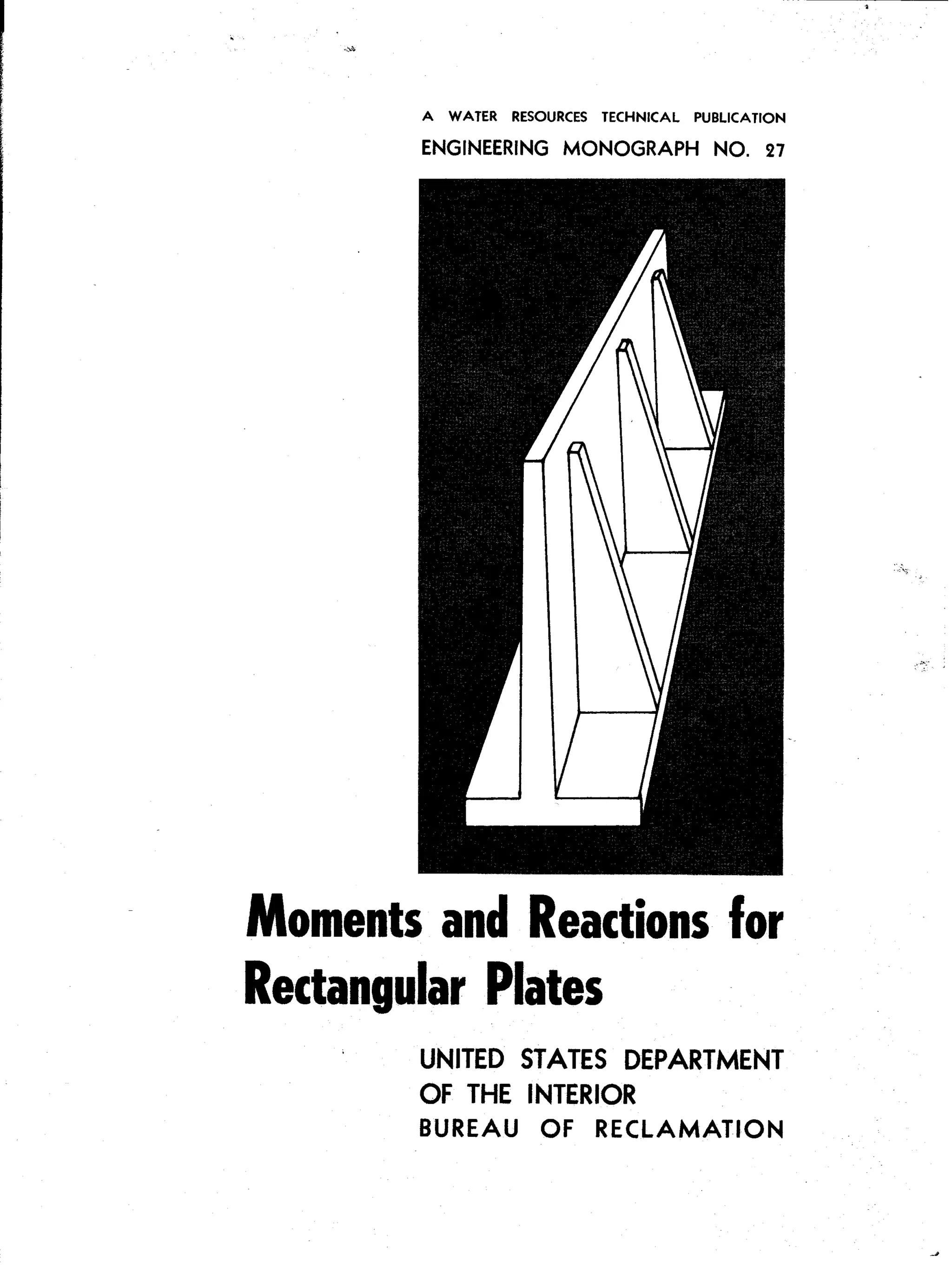
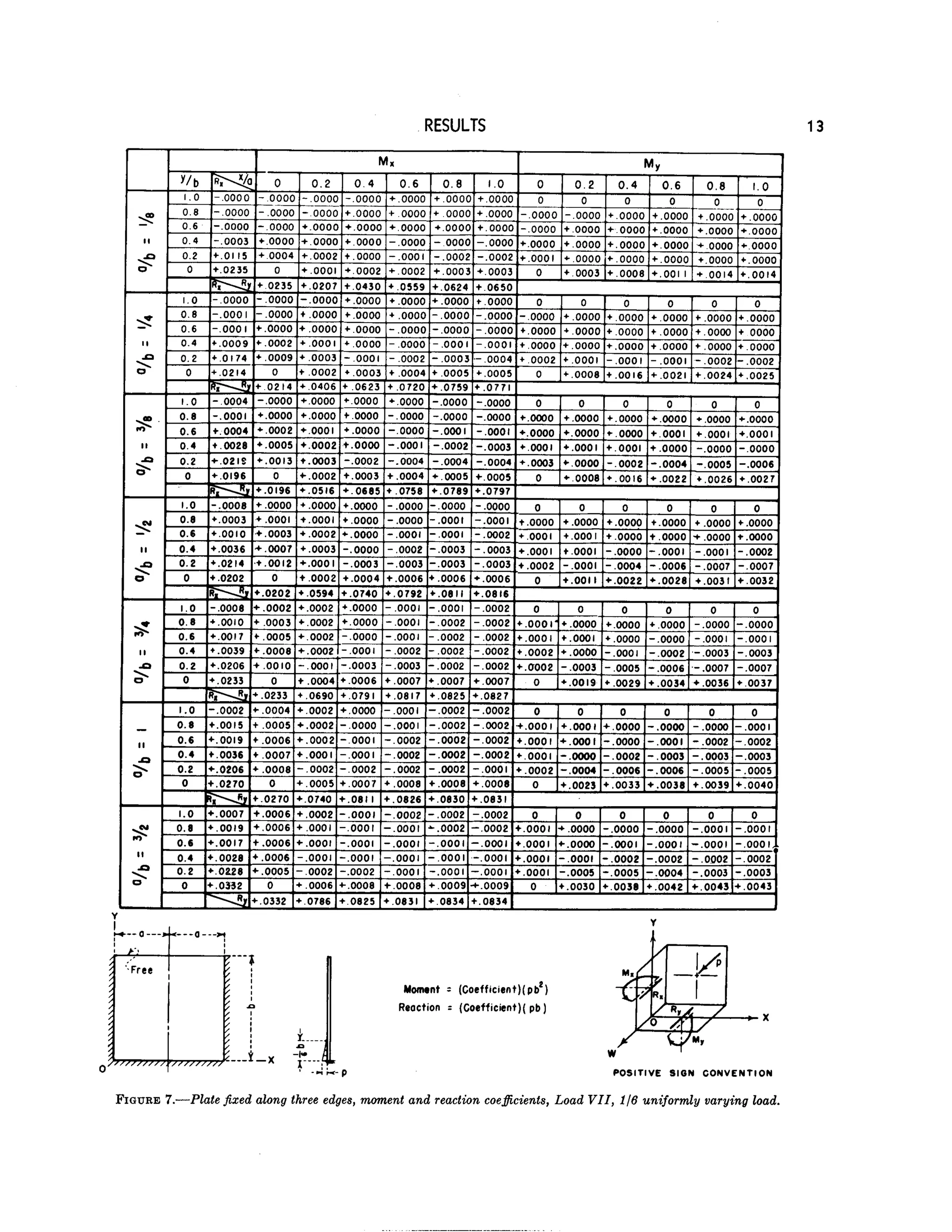
This document provides tables of computed moment and reaction coefficients for rectangular plates under different loading and boundary conditions. The tables allow engineers to quickly analyze plate components in structures by providing normalized moment and reaction values for a variety of plate geometry ratios and representative load cases, including uniform, varying, point, and line loads. Five boundary conditions, nine ratios of plate dimensions, and eleven representative load cases are considered. Supplementary appendices demonstrate an example application and explain the finite difference method used to generate the table values.


