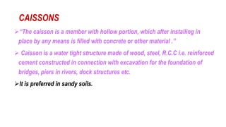
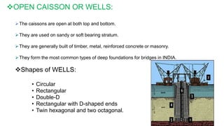
1. Caissons are hollow structures that are installed in place and then filled with concrete or other material. They are used as foundations under water.
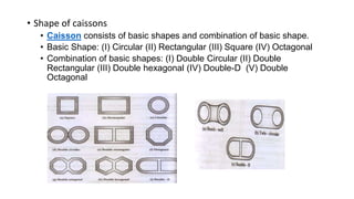
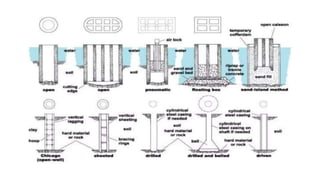
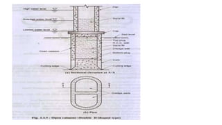
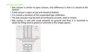
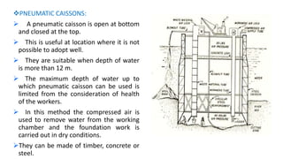
2. There are three main types of caissons - open caissons which are open at the top and bottom, box caissons which are closed at the bottom, and pneumatic caissons which are closed at the top and use compressed air.
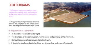
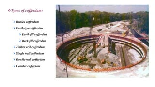
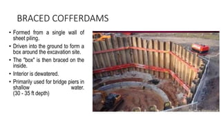
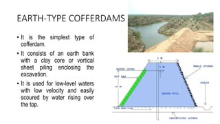
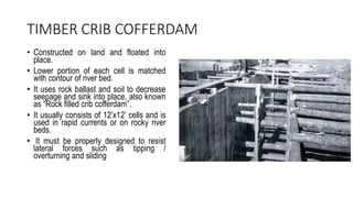
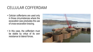
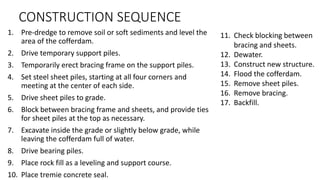
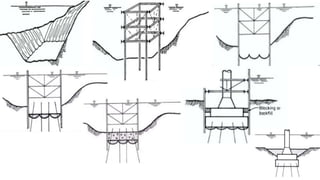
3. Cofferdams are temporary structures built around construction sites under water. They exclude surface and ground water to provide a dry work area. Common types include braced, earth-fill, timber crib, and double-walled sheet pile cofferdams.