Downloaded 726 times
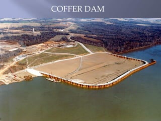

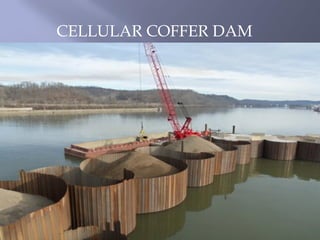
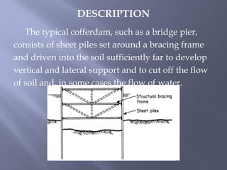


1. A cofferdam is a temporary structure built around construction sites located underwater to allow workers to perform construction in a dry environment. It is constructed by driving sheet piling into the ground and placing concrete along the bottom to seal it off from water seepage. 2. The main types of cofferdams are braced, earth-type, timber crib, double-walled sheet pile, and cellular. Their construction involves setting up sheet piling, installing bracing frames, placing a concrete seal, and sometimes using bearing piles before dewatering the site. 3. Safety is the top priority in cofferdam construction due to the risk of flooding. Proper design, construction oversight


