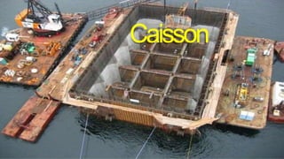
SlideShare a Scribd company logo
Caisson
Caisson
• Introduction
• Uses of caisson
• Material used for
caisson
• Type of caisson
• Load on caisson
• Design feature of
caissons
• Floating of caisson
• Cutting edge
• Sinking of caisson
• Problem in well sinking
Caissons
• The term caisson is derived from French word caisse means
BOX.
• Caisson is a watertight structure round or rectangular, which is
sunk through ground or water to exclude water and semi-fluid
material during the process of excavation of foundation and
which subsequently becomes an integral part of the
substructure.
Usesof caissons
the hard bearing strata for transferring the load of
superstructure.
• For the excavation for foundation of bridges, piers, abutments in
river and lakes.
• T
o serve as an impervious core wall of earth dam, when
placed adjacent to each other.
• To provide access to a deep shaft or tunnel
• T
o provide an enclosurebelow water level for installing
machinery pump.
To reach
Material usedforcaissons
• Steel
• Timber
• Reinforced cement
concrete
• Cast iron
S
teel
• It is most suitable material for the construction of a caisson.
• It have form of a double skin of steel plating and hollow space
which can filled with cement concrete.
Reinforced cement concrete
• It is suitable for caisson shoes.
• It becomecostly in the early stageof constructionas more
weight creates problem is handling and floating of caisson.
• It become economicalto construct a steel caissonwith
concrete lining.
Castiron
• It is suitable for open well type of caisson.
• New segment of C.I are bolted as the caisson sinks.
• It is not suitable for pneumatic caisson due to risk to
tension developed by the compressed air.
• The cost of C.I. caisson is more as compared to steel
and RCC.
Typesof caissons
• Box caisson
(Open at top and closed at
bottom)
• Open caissons
(Open at top and bottom)
• Pneumatic caisson
(Closed at top and open at
bottom)
Boxcaisson
• It is strong water tight vessel open at
top and closed at bottom and made
of timber, steel or RCC.
• It is build on land , cured and then
float or launched to pier site where
it is placed in position.
• Mainly it is used for shallow depth
and for light weight.
Conditions for Construction ofbox caisson
• Excavation for foundation is not required. The bed of foundation
can previously prepared.
• The velocity of flow of water is slow so as to give stability to
the caisson against scouring.
• The bed material is loose enough and it is possible to dredge
out this material and from a levelled bearing surface.
• The depth of water is about 6 to 8 m.
Open Caissons Or Wells
• Open caisson is a box of timber,
reinforced concrete, steel or
masonry which is open at the top
and at bottom.
• It used for building and bridge
foundation .
• Open caisson are also called
well
foundation.
• They are used on sandy or soft
bearing stratum liable to scour and
where no
firm bed available for large
depth below the surface.
TypesOf OpenCaisson
• Single well
• Multiple well
/monoliths
• cylinder
ShapesOf Wells
• Single circular
• Rectangular
• Twin circular
• Dumb well
• Double-D
• Twin-
hexagonal
• Twin-
octagonal
ShapesOf Wells
Factor ForChoiceOf ShapeOfWell
• The dimension of base of the pier of abutment.
• The case of sinking.
• The cost of sinking and shuttering.
• The vertical and horizontal forces acting on the
well.
• The considerations of tilt and shift during
sinking.
Component OfWell
• Cutting
edge
• Curb
• Steining
• Bottom
plug
• Top plug
• Well cap
• Sand filling
• Cutting edge
Provides sharp edge to cut the soil below during sinking
operation.
• Curb
During sinking it acts as extension of cutting edge and provide
support the well. It is made of RCC.
• Steining
It is main body of the well. Made of RCC or masonry with
minimum thickness of 45 cm.
• Bottom plug
Made of concrete and designed for an
upward load equal to the
soil pressure minus self weight of the
bottom plug and sand filling.
• Top plug
It supports the well cap.
• Well cap
It transfers the load from pier to the well.
• Sand filling
It transfers a portion of load from well cap to the bottom plug.
Well Sinking Operations
• For dry ground open excavation up to half a meter above subsoil water
level is carried out and the well curb is laid.
• Well Steining built in short height about 2 m.
• Well is sunk by excavating material from inside the curb
where excavation may carried out by worker or dredger.
• “Kentledge” is applied on well by iron rail or sand
bag to counter skin frication and loss in the weight of well due
to buoyancy.
• Pumping out the water from inside the well when well has gone
deep enough.
• A concrete plug is provide at the bottom which made bowl shaped.
• Internal space is filled with sand and top of well provide concrete with
RCC cap.
Multiple well/Monoliths
• The monoliths consists of multiple
wells, which are sunk together.
• The individual well of the monoliths
has got separate cutting edge and the
dredging can be done in each of the
well separately.
• It having bigger dimension so they can
not built on the site in the water.
• Therefore, they are constructed in dry
place, floated and placed in final
position.
Construction
• A suitable site is selected on the upstream side of the proposed bridge in a
river and a dry dock is constructed.
• Dimensionof the dry dock is bigger then monolith and it should
provided sufficient width of door.
• The monolith is constructed in the dry dock to such a height that some
portion of
it remain above water level.
• The gate of the dry dock is opened the monolith is then floated and located
in its correct position.
• Dredging operation done in sequence as four dredging well used
simultaneously
and the middle row is touched
last.
• After dredging to the required depth the whole monolith is gradually sunk
up to required level.
• The bottom is provided with concrete seal and then filled with concrete and
cap is provided at top.
Pneumaticcaisson
Pneumaticcaisson
• A pneumatic caisson is open at bottom and closed at top.
• It is useful at location where well is not possible.
• It suitable for water depth of 12 m to 35 m.
• Compressed air is used to remove water from working chamber
at the bottom and foundation work is carried out in dry
condition.
• The pressure of air in chamber is higher than water at that depth
for subsoil water may not enter in working chamber.
• The maximum pressure is limited up to 0.35 N/mm2 .
Construction
• The caisson is sunk in water till no problem is encounter. When
water creates problem the air lock is placed inside the well.
• There are two air locks are provided in caisson one for sending
men inside and second for removing the excavated material
with help of muck bucket and hosting rope.
• After the lock is placed in position direct entry of air is sealed
water is pumped out from the bottom and compressed air is
prevent the entry of water from bottom.
• The work of foundation is then started by sending the labour in
to working chamber.
Construction conti..
• The height of chamber is kept about 2m and lighting
arrangement is provided.
• The excavation material may be taken out
by a muck hoisted by a rope or cable.
• The explosive or reduction of air pressure for a short duration
may be applied.
• When a caissonhas reached the desired level a concrete seal
is provided at bottom .
• The air lock and other equipment removedand filling caisson
with suitable material.
Pneumatic caissonsickness
• Dizziness
• Double vision
• Headache
• Trouble to
speaking
• Pain in lag
• Etc.
Precautions to avoidsickness
• Work only for one shift in a day
• Duration of shift should not exceed 12 hours.
• Maintain temp. 250 C.
• Persons employed on the work should be physically fit.
• The main lock should be well-ventilated.
• Medical chamber must be provided just near the side of
work
• Etc.. As per your view
LoadsOnCaisson
• Vertical load
• Lateral load
• Sinking load
• Seismic forces
• Longitude force
• Wind force
• Centrifugal force in case of well on a
curve
Floating of caisson
• Construction of dry
dock
• Floating from bank
• Turning of caisson
• Use of compressed air
Construction Of DryDock
• A dry dock is constructed on the upstream side of the bridge
site.
• After construction of caisson in dock it may flooded to float
out.
• The caisson should be properly anchored when it is
floating and landing.
Floating frombank
Turning of caissons
• This method is used when depth of water is high.
• The caisson is launched upside down cutting edge is upward
and top is at bottom.
• The portion on one side is kept slightly higher than the
remaining one.
• Sand is used to maintain symmetry during launching.stone
ballast and water are then added to cause tilting of the caisson.
• When complete turning occurs, the caisson starts floating
in the water and stone ballast falls out of the caisson.
CompressedAir
• The completed portion of caisson is provided with a steel
dome and the compressed air is applied through it.
• The compressed air keeps out water and facilitates the
floating of caisson.
• When the caisson settles down at its proper position the steel
dome is removed.
CuttingEdge
• It should be sharp angle for knifing into the soil to resist the
various stresses induced by boulders blow, blasting, etc.
• It should be well protected by the steel point to avoid any
damage to the edge
• The outer edge should be vertical
• In case of pneumatic caisson it should be air tight.
• If water jet is to be used for sinkingpurposethe nozzleshould
be accommodated in the cutting edge to reduce skin friction.
• In concretecaisson the lower portion of the
cutting edge is rigidly fastened with 12 mm steel plate
with help of steel straps.
Typesof cuttingedges
1. Cutting edge with sharp
ends
2. Cutting edge with blunt
ends
Cutting edgewith sharpends
• Cutting edge shown
in fig (a) and fig. (b)
are used for open
cylinder/ caisson.
• Fig. (c ) is used for
pneumatic caisson.
Cutting edgewith bluntends
• a is suitable for Avg. condition
of sinking
• b is suitable when a caisson is to
be
sunk through rock
• C is suitable when it is to be built
from a land surface.
Factors to selection of acuttingedge
• Method of sinking to be adopted.
• Construction method of caisson
• Nature of soil
• Nature of ultimate soil stratum on which the cutting edge is to
rest while concrete is being placed for the bottom plug.
Sinkingof caisson
• Various method for sinking of caisson are here
below;
• Air and water jets
• Blasting
• Loading
• Sand island
Air and Waterjets
• Jet are provided near the cutting edge level to reduce the skin
friction
• It may be embodied in the body of the caisson or it may be
operated independently by driver or other workmen.
• The air or water is forced through the jets which ultimately
facilitates the sinking of caisson.
Blasting
• Explosive are used to remove any obstruction like rock, boulder
etc .
• It is reduce skin friction of hard soils.
• for blasting gelignite is used which is a absorbing powder and
blasting gelatin.
• It is powerful under water and convenient to use.
• It is necessary to take
extreme care to see that the cutting edge
of caisson is not damage during the blasting operation.
Loading
Sandisland
• It is used when subsoil condition are
such that it is not possible to kept the
caisson stable.
• In this method sinking a steel cylinder
around the site of work and then filling
this cylinder with sand or other
dredged material.
• The caisson is sunk through this
filling in
the usual manner.
• It is also known as artificial island
method.
Problem in wellsinking
• Sand blowing
• Tilting of wells
• Shifting of
wells
Sandblowing
• Sand blowing is takes place during the process off dewatering
of the well passing through sandy strata.
• The ground around the well starts breaking up to wide
cracks are seen in it.
• The fall of sand in the caisson is sudden and huge amount to a
depth of about 3 to 15 m of sand.
• This may result in a fatal accident and the equipment and
worker may get buried during sand blowing.
Shifting of wells
• The shifts change span
length and thereby
induced loads on the
well staining and the
foundation.
• The magnitude of the ill
effect depend upon the
size of well and depth of
which it is sunk.
Tilting ofwells
• Control of dredging
• Eccentric loading
• Water jetting
• Pulling the well
• Pushing by jacks
• Use of explosive
• Deposition of earth on one side and excavation on
other
• Providing temporary obstacle below the cutting
edge
CAISSON PPT.pptx

More Related Content

Similar to CAISSON PPT.pptx

Cofferdams
Cofferdams Cofferdams
Cofferdams
GAURAV. H .TANDON
 
Cofferdam_ppt.pptx
Cofferdam_ppt.pptxCofferdam_ppt.pptx
Cofferdam_ppt.pptx
JackRider12
 
Well Foundation
Well FoundationWell Foundation
Well Foundation
Dave Chinmyee
 
Chapter 4.3 well foundation-final-ppt
Chapter 4.3   well foundation-final-pptChapter 4.3   well foundation-final-ppt
Chapter 4.3 well foundation-final-ppt
DYPCET
 
2. CAISSONS (ACE) 2160601 GTU
2. CAISSONS (ACE) 2160601 GTU2. CAISSONS (ACE) 2160601 GTU
2. CAISSONS (ACE) 2160601 GTU
VATSAL PATEL
 
Well foundation
Well foundationWell foundation
Earthen Dams
Earthen DamsEarthen Dams
Earthen Dams
GAURAV. H .TANDON
 
Sinking of well foundation
Sinking of well foundationSinking of well foundation
Sinking of well foundation
Sourabh Jain
 
Pile foundations
Pile foundationsPile foundations
Pile foundations
Sameer Thaiyam
 
Underwater construction
Underwater construction Underwater construction
Underwater construction
Pranay Kumar
 
Cofferdam
CofferdamCofferdam
Cofferdam
Shashank Namdeo
 
R22 bunker storage of grains
R22 bunker storage of grainsR22 bunker storage of grains
R22 bunker storage of grains
Maya Sharma
 
WELL COMPLETIONS.pptx
WELL COMPLETIONS.pptxWELL COMPLETIONS.pptx
WELL COMPLETIONS.pptx
DagogoGreenFurosigha
 
pire and well.pptx
pire and  well.pptxpire and  well.pptx
pire and well.pptx
NisthaPathak2
 
well foundation of six lane new ganga bridge near kacchi dargah in district P...
well foundation of six lane new ganga bridge near kacchi dargah in district P...well foundation of six lane new ganga bridge near kacchi dargah in district P...
well foundation of six lane new ganga bridge near kacchi dargah in district P...
Arman Hashmi
 
BC-II lec 6 pierand deep fdn.pptx
BC-II lec 6 pierand deep fdn.pptxBC-II lec 6 pierand deep fdn.pptx
BC-II lec 6 pierand deep fdn.pptx
NisthaPathak2
 
Coffer Dams and Caissons
Coffer Dams and CaissonsCoffer Dams and Caissons
Coffer Dams and CaissonsRizwan Samor
 
1619929813526_College Deep Well Foundation Project.pptx
1619929813526_College Deep Well Foundation Project.pptx1619929813526_College Deep Well Foundation Project.pptx
1619929813526_College Deep Well Foundation Project.pptx
AkshayGhorpade19
 
Dams and spillways
Dams and spillwaysDams and spillways
1.6 caisson
1.6 caisson1.6 caisson
1.6 caisson
Rafique Ahmed Sayed
 

Similar to CAISSON PPT.pptx (20)

Cofferdams
Cofferdams Cofferdams
Cofferdams
 
Cofferdam_ppt.pptx
Cofferdam_ppt.pptxCofferdam_ppt.pptx
Cofferdam_ppt.pptx
 
Well Foundation
Well FoundationWell Foundation
Well Foundation
 
Chapter 4.3 well foundation-final-ppt
Chapter 4.3   well foundation-final-pptChapter 4.3   well foundation-final-ppt
Chapter 4.3 well foundation-final-ppt
 
2. CAISSONS (ACE) 2160601 GTU
2. CAISSONS (ACE) 2160601 GTU2. CAISSONS (ACE) 2160601 GTU
2. CAISSONS (ACE) 2160601 GTU
 
Well foundation
Well foundationWell foundation
Well foundation
 
Earthen Dams
Earthen DamsEarthen Dams
Earthen Dams
 
Sinking of well foundation
Sinking of well foundationSinking of well foundation
Sinking of well foundation
 
Pile foundations
Pile foundationsPile foundations
Pile foundations
 
Underwater construction
Underwater construction Underwater construction
Underwater construction
 
Cofferdam
CofferdamCofferdam
Cofferdam
 
R22 bunker storage of grains
R22 bunker storage of grainsR22 bunker storage of grains
R22 bunker storage of grains
 
WELL COMPLETIONS.pptx
WELL COMPLETIONS.pptxWELL COMPLETIONS.pptx
WELL COMPLETIONS.pptx
 
pire and well.pptx
pire and  well.pptxpire and  well.pptx
pire and well.pptx
 
well foundation of six lane new ganga bridge near kacchi dargah in district P...
well foundation of six lane new ganga bridge near kacchi dargah in district P...well foundation of six lane new ganga bridge near kacchi dargah in district P...
well foundation of six lane new ganga bridge near kacchi dargah in district P...
 
BC-II lec 6 pierand deep fdn.pptx
BC-II lec 6 pierand deep fdn.pptxBC-II lec 6 pierand deep fdn.pptx
BC-II lec 6 pierand deep fdn.pptx
 
Coffer Dams and Caissons
Coffer Dams and CaissonsCoffer Dams and Caissons
Coffer Dams and Caissons
 
1619929813526_College Deep Well Foundation Project.pptx
1619929813526_College Deep Well Foundation Project.pptx1619929813526_College Deep Well Foundation Project.pptx
1619929813526_College Deep Well Foundation Project.pptx
 
Dams and spillways
Dams and spillwaysDams and spillways
Dams and spillways
 
1.6 caisson
1.6 caisson1.6 caisson
1.6 caisson
 

Recently uploaded

Nuclear Power Economics and Structuring 2024
Nuclear Power Economics and Structuring 2024Nuclear Power Economics and Structuring 2024
Nuclear Power Economics and Structuring 2024
Massimo Talia
 
Sachpazis:Terzaghi Bearing Capacity Estimation in simple terms with Calculati...
Sachpazis:Terzaghi Bearing Capacity Estimation in simple terms with Calculati...Sachpazis:Terzaghi Bearing Capacity Estimation in simple terms with Calculati...
Sachpazis:Terzaghi Bearing Capacity Estimation in simple terms with Calculati...
Dr.Costas Sachpazis
 
AKS UNIVERSITY Satna Final Year Project By OM Hardaha.pdf
AKS UNIVERSITY Satna Final Year Project By OM Hardaha.pdfAKS UNIVERSITY Satna Final Year Project By OM Hardaha.pdf
AKS UNIVERSITY Satna Final Year Project By OM Hardaha.pdf
SamSarthak3
 
Courier management system project report.pdf
Courier management system project report.pdfCourier management system project report.pdf
Courier management system project report.pdf
Kamal Acharya
 
Water Industry Process Automation and Control Monthly - May 2024.pdf
Water Industry Process Automation and Control Monthly - May 2024.pdfWater Industry Process Automation and Control Monthly - May 2024.pdf
Water Industry Process Automation and Control Monthly - May 2024.pdf
Water Industry Process Automation & Control
 
power quality voltage fluctuation UNIT - I.pptx
power quality voltage fluctuation UNIT - I.pptxpower quality voltage fluctuation UNIT - I.pptx
power quality voltage fluctuation UNIT - I.pptx
ViniHema
 
Pile Foundation by Venkatesh Taduvai (Sub Geotechnical Engineering II)-conver...
Pile Foundation by Venkatesh Taduvai (Sub Geotechnical Engineering II)-conver...Pile Foundation by Venkatesh Taduvai (Sub Geotechnical Engineering II)-conver...
Pile Foundation by Venkatesh Taduvai (Sub Geotechnical Engineering II)-conver...
AJAYKUMARPUND1
 
Top 10 Oil and Gas Projects in Saudi Arabia 2024.pdf
Top 10 Oil and Gas Projects in Saudi Arabia 2024.pdfTop 10 Oil and Gas Projects in Saudi Arabia 2024.pdf
Top 10 Oil and Gas Projects in Saudi Arabia 2024.pdf
Teleport Manpower Consultant
 
addressing modes in computer architecture
addressing modes  in computer architectureaddressing modes  in computer architecture
addressing modes in computer architecture
ShahidSultan24
 
H.Seo, ICLR 2024, MLILAB, KAIST AI.pdf
H.Seo,  ICLR 2024, MLILAB,  KAIST AI.pdfH.Seo,  ICLR 2024, MLILAB,  KAIST AI.pdf
H.Seo, ICLR 2024, MLILAB, KAIST AI.pdf
MLILAB
 
WATER CRISIS and its solutions-pptx 1234
WATER CRISIS and its solutions-pptx 1234WATER CRISIS and its solutions-pptx 1234
WATER CRISIS and its solutions-pptx 1234
AafreenAbuthahir2
 
Cosmetic shop management system project report.pdf
Cosmetic shop management system project report.pdfCosmetic shop management system project report.pdf
Cosmetic shop management system project report.pdf
Kamal Acharya
 
block diagram and signal flow graph representation
block diagram and signal flow graph representationblock diagram and signal flow graph representation
block diagram and signal flow graph representation
Divya Somashekar
 
在线办理(ANU毕业证书)澳洲国立大学毕业证录取通知书一模一样
在线办理(ANU毕业证书)澳洲国立大学毕业证录取通知书一模一样在线办理(ANU毕业证书)澳洲国立大学毕业证录取通知书一模一样
在线办理(ANU毕业证书)澳洲国立大学毕业证录取通知书一模一样
obonagu
 
road safety engineering r s e unit 3.pdf
road safety engineering  r s e unit 3.pdfroad safety engineering  r s e unit 3.pdf
road safety engineering r s e unit 3.pdf
VENKATESHvenky89705
 
COLLEGE BUS MANAGEMENT SYSTEM PROJECT REPORT.pdf
COLLEGE BUS MANAGEMENT SYSTEM PROJECT REPORT.pdfCOLLEGE BUS MANAGEMENT SYSTEM PROJECT REPORT.pdf
COLLEGE BUS MANAGEMENT SYSTEM PROJECT REPORT.pdf
Kamal Acharya
 
Railway Signalling Principles Edition 3.pdf
Railway Signalling Principles Edition 3.pdfRailway Signalling Principles Edition 3.pdf
Railway Signalling Principles Edition 3.pdf
TeeVichai
 
Standard Reomte Control Interface - Neometrix
Standard Reomte Control Interface - NeometrixStandard Reomte Control Interface - Neometrix
Standard Reomte Control Interface - Neometrix
Neometrix_Engineering_Pvt_Ltd
 
Quality defects in TMT Bars, Possible causes and Potential Solutions.
Quality defects in TMT Bars, Possible causes and Potential Solutions.Quality defects in TMT Bars, Possible causes and Potential Solutions.
Quality defects in TMT Bars, Possible causes and Potential Solutions.
PrashantGoswami42
 
MCQ Soil mechanics questions (Soil shear strength).pdf
MCQ Soil mechanics questions (Soil shear strength).pdfMCQ Soil mechanics questions (Soil shear strength).pdf
MCQ Soil mechanics questions (Soil shear strength).pdf
Osamah Alsalih
 

Recently uploaded (20)

Nuclear Power Economics and Structuring 2024
Nuclear Power Economics and Structuring 2024Nuclear Power Economics and Structuring 2024
Nuclear Power Economics and Structuring 2024
 
Sachpazis:Terzaghi Bearing Capacity Estimation in simple terms with Calculati...
Sachpazis:Terzaghi Bearing Capacity Estimation in simple terms with Calculati...Sachpazis:Terzaghi Bearing Capacity Estimation in simple terms with Calculati...
Sachpazis:Terzaghi Bearing Capacity Estimation in simple terms with Calculati...
 
AKS UNIVERSITY Satna Final Year Project By OM Hardaha.pdf
AKS UNIVERSITY Satna Final Year Project By OM Hardaha.pdfAKS UNIVERSITY Satna Final Year Project By OM Hardaha.pdf
AKS UNIVERSITY Satna Final Year Project By OM Hardaha.pdf
 
Courier management system project report.pdf
Courier management system project report.pdfCourier management system project report.pdf
Courier management system project report.pdf
 
Water Industry Process Automation and Control Monthly - May 2024.pdf
Water Industry Process Automation and Control Monthly - May 2024.pdfWater Industry Process Automation and Control Monthly - May 2024.pdf
Water Industry Process Automation and Control Monthly - May 2024.pdf
 
power quality voltage fluctuation UNIT - I.pptx
power quality voltage fluctuation UNIT - I.pptxpower quality voltage fluctuation UNIT - I.pptx
power quality voltage fluctuation UNIT - I.pptx
 
Pile Foundation by Venkatesh Taduvai (Sub Geotechnical Engineering II)-conver...
Pile Foundation by Venkatesh Taduvai (Sub Geotechnical Engineering II)-conver...Pile Foundation by Venkatesh Taduvai (Sub Geotechnical Engineering II)-conver...
Pile Foundation by Venkatesh Taduvai (Sub Geotechnical Engineering II)-conver...
 
Top 10 Oil and Gas Projects in Saudi Arabia 2024.pdf
Top 10 Oil and Gas Projects in Saudi Arabia 2024.pdfTop 10 Oil and Gas Projects in Saudi Arabia 2024.pdf
Top 10 Oil and Gas Projects in Saudi Arabia 2024.pdf
 
addressing modes in computer architecture
addressing modes  in computer architectureaddressing modes  in computer architecture
addressing modes in computer architecture
 
H.Seo, ICLR 2024, MLILAB, KAIST AI.pdf
H.Seo,  ICLR 2024, MLILAB,  KAIST AI.pdfH.Seo,  ICLR 2024, MLILAB,  KAIST AI.pdf
H.Seo, ICLR 2024, MLILAB, KAIST AI.pdf
 
WATER CRISIS and its solutions-pptx 1234
WATER CRISIS and its solutions-pptx 1234WATER CRISIS and its solutions-pptx 1234
WATER CRISIS and its solutions-pptx 1234
 
Cosmetic shop management system project report.pdf
Cosmetic shop management system project report.pdfCosmetic shop management system project report.pdf
Cosmetic shop management system project report.pdf
 
block diagram and signal flow graph representation
block diagram and signal flow graph representationblock diagram and signal flow graph representation
block diagram and signal flow graph representation
 
在线办理(ANU毕业证书)澳洲国立大学毕业证录取通知书一模一样
在线办理(ANU毕业证书)澳洲国立大学毕业证录取通知书一模一样在线办理(ANU毕业证书)澳洲国立大学毕业证录取通知书一模一样
在线办理(ANU毕业证书)澳洲国立大学毕业证录取通知书一模一样
 
road safety engineering r s e unit 3.pdf
road safety engineering  r s e unit 3.pdfroad safety engineering  r s e unit 3.pdf
road safety engineering r s e unit 3.pdf
 
COLLEGE BUS MANAGEMENT SYSTEM PROJECT REPORT.pdf
COLLEGE BUS MANAGEMENT SYSTEM PROJECT REPORT.pdfCOLLEGE BUS MANAGEMENT SYSTEM PROJECT REPORT.pdf
COLLEGE BUS MANAGEMENT SYSTEM PROJECT REPORT.pdf
 
Railway Signalling Principles Edition 3.pdf
Railway Signalling Principles Edition 3.pdfRailway Signalling Principles Edition 3.pdf
Railway Signalling Principles Edition 3.pdf
 
Standard Reomte Control Interface - Neometrix
Standard Reomte Control Interface - NeometrixStandard Reomte Control Interface - Neometrix
Standard Reomte Control Interface - Neometrix
 
Quality defects in TMT Bars, Possible causes and Potential Solutions.
Quality defects in TMT Bars, Possible causes and Potential Solutions.Quality defects in TMT Bars, Possible causes and Potential Solutions.
Quality defects in TMT Bars, Possible causes and Potential Solutions.
 
MCQ Soil mechanics questions (Soil shear strength).pdf
MCQ Soil mechanics questions (Soil shear strength).pdfMCQ Soil mechanics questions (Soil shear strength).pdf
MCQ Soil mechanics questions (Soil shear strength).pdf
 

CAISSON PPT.pptx

  • 2. Caisson • Introduction • Uses of caisson • Material used for caisson • Type of caisson • Load on caisson • Design feature of caissons • Floating of caisson • Cutting edge • Sinking of caisson • Problem in well sinking
  • 3. Caissons • The term caisson is derived from French word caisse means BOX. • Caisson is a watertight structure round or rectangular, which is sunk through ground or water to exclude water and semi-fluid material during the process of excavation of foundation and which subsequently becomes an integral part of the substructure.
  • 4. Usesof caissons the hard bearing strata for transferring the load of superstructure. • For the excavation for foundation of bridges, piers, abutments in river and lakes. • T o serve as an impervious core wall of earth dam, when placed adjacent to each other. • To provide access to a deep shaft or tunnel • T o provide an enclosurebelow water level for installing machinery pump. To reach
  • 5. Material usedforcaissons • Steel • Timber • Reinforced cement concrete • Cast iron
  • 6. S teel • It is most suitable material for the construction of a caisson. • It have form of a double skin of steel plating and hollow space which can filled with cement concrete.
  • 7. Reinforced cement concrete • It is suitable for caisson shoes. • It becomecostly in the early stageof constructionas more weight creates problem is handling and floating of caisson. • It become economicalto construct a steel caissonwith concrete lining.
  • 8. Castiron • It is suitable for open well type of caisson. • New segment of C.I are bolted as the caisson sinks. • It is not suitable for pneumatic caisson due to risk to tension developed by the compressed air. • The cost of C.I. caisson is more as compared to steel and RCC.
  • 9. Typesof caissons • Box caisson (Open at top and closed at bottom) • Open caissons (Open at top and bottom) • Pneumatic caisson (Closed at top and open at bottom)
  • 10. Boxcaisson • It is strong water tight vessel open at top and closed at bottom and made of timber, steel or RCC. • It is build on land , cured and then float or launched to pier site where it is placed in position. • Mainly it is used for shallow depth and for light weight.
  • 11. Conditions for Construction ofbox caisson • Excavation for foundation is not required. The bed of foundation can previously prepared. • The velocity of flow of water is slow so as to give stability to the caisson against scouring. • The bed material is loose enough and it is possible to dredge out this material and from a levelled bearing surface. • The depth of water is about 6 to 8 m.
  • 12. Open Caissons Or Wells • Open caisson is a box of timber, reinforced concrete, steel or masonry which is open at the top and at bottom. • It used for building and bridge foundation . • Open caisson are also called well foundation. • They are used on sandy or soft bearing stratum liable to scour and where no firm bed available for large depth below the surface.
  • 13. TypesOf OpenCaisson • Single well • Multiple well /monoliths • cylinder
  • 14. ShapesOf Wells • Single circular • Rectangular • Twin circular • Dumb well • Double-D • Twin- hexagonal • Twin- octagonal
  • 16. Factor ForChoiceOf ShapeOfWell • The dimension of base of the pier of abutment. • The case of sinking. • The cost of sinking and shuttering. • The vertical and horizontal forces acting on the well. • The considerations of tilt and shift during sinking.
  • 17. Component OfWell • Cutting edge • Curb • Steining • Bottom plug • Top plug • Well cap • Sand filling
  • 18. • Cutting edge Provides sharp edge to cut the soil below during sinking operation. • Curb During sinking it acts as extension of cutting edge and provide support the well. It is made of RCC. • Steining It is main body of the well. Made of RCC or masonry with minimum thickness of 45 cm.
  • 19. • Bottom plug Made of concrete and designed for an upward load equal to the soil pressure minus self weight of the bottom plug and sand filling. • Top plug It supports the well cap. • Well cap It transfers the load from pier to the well. • Sand filling It transfers a portion of load from well cap to the bottom plug.
  • 20.
  • 21. Well Sinking Operations • For dry ground open excavation up to half a meter above subsoil water level is carried out and the well curb is laid. • Well Steining built in short height about 2 m. • Well is sunk by excavating material from inside the curb where excavation may carried out by worker or dredger. • “Kentledge” is applied on well by iron rail or sand bag to counter skin frication and loss in the weight of well due to buoyancy. • Pumping out the water from inside the well when well has gone deep enough. • A concrete plug is provide at the bottom which made bowl shaped. • Internal space is filled with sand and top of well provide concrete with RCC cap.
  • 22.
  • 23. Multiple well/Monoliths • The monoliths consists of multiple wells, which are sunk together. • The individual well of the monoliths has got separate cutting edge and the dredging can be done in each of the well separately. • It having bigger dimension so they can not built on the site in the water. • Therefore, they are constructed in dry place, floated and placed in final position.
  • 24. Construction • A suitable site is selected on the upstream side of the proposed bridge in a river and a dry dock is constructed. • Dimensionof the dry dock is bigger then monolith and it should provided sufficient width of door. • The monolith is constructed in the dry dock to such a height that some portion of it remain above water level. • The gate of the dry dock is opened the monolith is then floated and located in its correct position. • Dredging operation done in sequence as four dredging well used simultaneously and the middle row is touched last. • After dredging to the required depth the whole monolith is gradually sunk up to required level. • The bottom is provided with concrete seal and then filled with concrete and cap is provided at top.
  • 25.
  • 27. Pneumaticcaisson • A pneumatic caisson is open at bottom and closed at top. • It is useful at location where well is not possible. • It suitable for water depth of 12 m to 35 m. • Compressed air is used to remove water from working chamber at the bottom and foundation work is carried out in dry condition. • The pressure of air in chamber is higher than water at that depth for subsoil water may not enter in working chamber. • The maximum pressure is limited up to 0.35 N/mm2 .
  • 28. Construction • The caisson is sunk in water till no problem is encounter. When water creates problem the air lock is placed inside the well. • There are two air locks are provided in caisson one for sending men inside and second for removing the excavated material with help of muck bucket and hosting rope. • After the lock is placed in position direct entry of air is sealed water is pumped out from the bottom and compressed air is prevent the entry of water from bottom. • The work of foundation is then started by sending the labour in to working chamber.
  • 29. Construction conti.. • The height of chamber is kept about 2m and lighting arrangement is provided. • The excavation material may be taken out by a muck hoisted by a rope or cable. • The explosive or reduction of air pressure for a short duration may be applied. • When a caissonhas reached the desired level a concrete seal is provided at bottom . • The air lock and other equipment removedand filling caisson with suitable material.
  • 30. Pneumatic caissonsickness • Dizziness • Double vision • Headache • Trouble to speaking • Pain in lag • Etc.
  • 31. Precautions to avoidsickness • Work only for one shift in a day • Duration of shift should not exceed 12 hours. • Maintain temp. 250 C. • Persons employed on the work should be physically fit. • The main lock should be well-ventilated. • Medical chamber must be provided just near the side of work • Etc.. As per your view
  • 32.
  • 33. LoadsOnCaisson • Vertical load • Lateral load • Sinking load • Seismic forces • Longitude force • Wind force • Centrifugal force in case of well on a curve
  • 34. Floating of caisson • Construction of dry dock • Floating from bank • Turning of caisson • Use of compressed air
  • 35. Construction Of DryDock • A dry dock is constructed on the upstream side of the bridge site. • After construction of caisson in dock it may flooded to float out. • The caisson should be properly anchored when it is floating and landing.
  • 37. Turning of caissons • This method is used when depth of water is high. • The caisson is launched upside down cutting edge is upward and top is at bottom. • The portion on one side is kept slightly higher than the remaining one. • Sand is used to maintain symmetry during launching.stone ballast and water are then added to cause tilting of the caisson. • When complete turning occurs, the caisson starts floating in the water and stone ballast falls out of the caisson.
  • 38. CompressedAir • The completed portion of caisson is provided with a steel dome and the compressed air is applied through it. • The compressed air keeps out water and facilitates the floating of caisson. • When the caisson settles down at its proper position the steel dome is removed.
  • 39. CuttingEdge • It should be sharp angle for knifing into the soil to resist the various stresses induced by boulders blow, blasting, etc. • It should be well protected by the steel point to avoid any damage to the edge • The outer edge should be vertical • In case of pneumatic caisson it should be air tight. • If water jet is to be used for sinkingpurposethe nozzleshould be accommodated in the cutting edge to reduce skin friction. • In concretecaisson the lower portion of the cutting edge is rigidly fastened with 12 mm steel plate with help of steel straps.
  • 40. Typesof cuttingedges 1. Cutting edge with sharp ends 2. Cutting edge with blunt ends
  • 41. Cutting edgewith sharpends • Cutting edge shown in fig (a) and fig. (b) are used for open cylinder/ caisson. • Fig. (c ) is used for pneumatic caisson.
  • 42. Cutting edgewith bluntends • a is suitable for Avg. condition of sinking • b is suitable when a caisson is to be sunk through rock • C is suitable when it is to be built from a land surface.
  • 43. Factors to selection of acuttingedge • Method of sinking to be adopted. • Construction method of caisson • Nature of soil • Nature of ultimate soil stratum on which the cutting edge is to rest while concrete is being placed for the bottom plug.
  • 44. Sinkingof caisson • Various method for sinking of caisson are here below; • Air and water jets • Blasting • Loading • Sand island
  • 45. Air and Waterjets • Jet are provided near the cutting edge level to reduce the skin friction • It may be embodied in the body of the caisson or it may be operated independently by driver or other workmen. • The air or water is forced through the jets which ultimately facilitates the sinking of caisson.
  • 46. Blasting • Explosive are used to remove any obstruction like rock, boulder etc . • It is reduce skin friction of hard soils. • for blasting gelignite is used which is a absorbing powder and blasting gelatin. • It is powerful under water and convenient to use. • It is necessary to take extreme care to see that the cutting edge of caisson is not damage during the blasting operation.
  • 47.
  • 49. Sandisland • It is used when subsoil condition are such that it is not possible to kept the caisson stable. • In this method sinking a steel cylinder around the site of work and then filling this cylinder with sand or other dredged material. • The caisson is sunk through this filling in the usual manner. • It is also known as artificial island method.
  • 50. Problem in wellsinking • Sand blowing • Tilting of wells • Shifting of wells
  • 51. Sandblowing • Sand blowing is takes place during the process off dewatering of the well passing through sandy strata. • The ground around the well starts breaking up to wide cracks are seen in it. • The fall of sand in the caisson is sudden and huge amount to a depth of about 3 to 15 m of sand. • This may result in a fatal accident and the equipment and worker may get buried during sand blowing.
  • 52. Shifting of wells • The shifts change span length and thereby induced loads on the well staining and the foundation. • The magnitude of the ill effect depend upon the size of well and depth of which it is sunk.
  • 53. Tilting ofwells • Control of dredging • Eccentric loading • Water jetting • Pulling the well • Pushing by jacks • Use of explosive • Deposition of earth on one side and excavation on other • Providing temporary obstacle below the cutting edge