Download to read offline
![IOSR Journal of Electrical and Electronics Engineering (IOSR-JEEE)
e-ISSN: 2278-1676,p-ISSN: 2320-3331, Volume 5, Issue 6 (May. - Jun. 2013), PP 23-30
www.iosrjournals.org
www.iosrjournals.org 23 | Page
Design and Simulation of MEMS Based Gyroscope
Sujit Kumar, B. Hemalatha
Department of Instrumentation and Control EngineeringSRM University, KattankulathurChennai, Tamilnadu-
603203, India
Abstract: This paper represents a MEMS based gyroscope to measure orientation. Silicon-micro-machined
gyro is fabricated on the basis of resonators and they use vibrating mechanical element to sense rotation. The
vibratory measurement can be done by measuring the change in capacitance with respect to the voltage or force
applied in particular axis. Here MEMS based gyroscope has been designed from Lame mode resonator which is
a square plate. The additional benefits by using the gyroscope are lower sensor cost, power consumption, more
robustness, higher shock resistance. In this paper, also sensitivity of the geometry and change of capacitance
has been shown.
Index Terms –Coriolis Force, Gyroscope, MEMS.
I. INTRODUCTION
Equipment for sensing, which includes the cameras, navigational instruments, electronic imaging
devices etc., are frequently carried by moving vehicle for different purposes and operated in the vehicle, such as
airplane which undergoes rotational motion about its center of rotation. MEMS based gyroscope is an inertial
sensor which provides the angular orientation of such sensing equipment. Gyroscope has two mode– driving and
sensing mode.Proposed design of gyroscope is in 3-axis whose working principle is based on the transfer of
energy between driving mode & sensing mode of gyroscope which is caused by Coriolis acceleration.Whenever
gyroscope will be subjectedto rotate in respective rotating axis then sensing mode will sense that rotation in
terms of change in capacitance. A significant costdriver in traditional stabilization systems is thegyroscope.
With the advanced technology of MEMS, MEMS based gyroscope has been applied to automotive application,
robotic & military application for different purpose. MEMS gyroscopes have a wide application spectrum in the
automotive and consumer electronics markets [1]. This is due to their reduced costs, size and integration
capability. Vibrating micro-machined gyroscopes that utilize vibrating elements to induce and detect coriolis
force have been effectively implemented and demonstrated in various micromachining-based batch fabrication
processes.
II. WORKING PRINCIPLE OF A GYROSCOPE
A Gyroscope is a sensor that measures the rate of rotation of an object. Since gyroscope has two
modes for actuating and sensing. Vibrating gyroscopes must be driven at resonance in order to function as
angular rate sensors. This direction will be referred as the drive direction. When the device is rotated along the
rotation axis, a coriolis force is induced in the sense direction which will be orthogonal to both axis. The force
will excite the device in sense direction into resonance mode. The sense direction is orthogonal to both the drive
direction and the rotation axis. The sense and drive direction, can be viewed as a mass-spring damper system.
Hence, a gyroscope can be viewed as a two degrees-of-freedom (2-DOF) mass-spring damper system whereby,
one degree of freedom is the drive direction, and the second degree of freedom orthogonal to the first is the
sense direction.
Fig 1.0: Generic model of a gyroscope
The coriolis acceleration is an apparent acceleration that arises in the rotation reference frame and it is
proportional to the rate of rotation. The coriolis force couples the sense and drive directions of the gyroscope
(figure 1.1). For understanding the dynamics and principle of operation of a gyroscope, the equations of motions
of a simple mass-spring damper system (figure 1.1) has been derived [4].](https://image.slidesharecdn.com/c0562330-140503013315-phpapp02/85/Design-and-Simulation-of-MEMS-Based-Gyroscope-1-320.jpg)
![IOSR Journal of Electrical and Electronics Engineering (IOSR-JEEE)
e-ISSN: 2278-1676,p-ISSN: 2320-3331, Volume 5, Issue 6 (May. - Jun. 2013), PP 23-30
www.iosrjournals.org
www.iosrjournals.org 23 | Page
Design and Simulation of MEMS Based Gyroscope
Sujit Kumar, B. Hemalatha
Department of Instrumentation and Control EngineeringSRM University, KattankulathurChennai, Tamilnadu-
603203, India
Abstract: This paper represents a MEMS based gyroscope to measure orientation. Silicon-micro-machined
gyro is fabricated on the basis of resonators and they use vibrating mechanical element to sense rotation. The
vibratory measurement can be done by measuring the change in capacitance with respect to the voltage or force
applied in particular axis. Here MEMS based gyroscope has been designed from Lame mode resonator which is
a square plate. The additional benefits by using the gyroscope are lower sensor cost, power consumption, more
robustness, higher shock resistance. In this paper, also sensitivity of the geometry and change of capacitance
has been shown.
Index Terms –Coriolis Force, Gyroscope, MEMS.
I. INTRODUCTION
Equipment for sensing, which includes the cameras, navigational instruments, electronic imaging
devices etc., are frequently carried by moving vehicle for different purposes and operated in the vehicle, such as
airplane which undergoes rotational motion about its center of rotation. MEMS based gyroscope is an inertial
sensor which provides the angular orientation of such sensing equipment. Gyroscope has two mode– driving and
sensing mode.Proposed design of gyroscope is in 3-axis whose working principle is based on the transfer of
energy between driving mode & sensing mode of gyroscope which is caused by Coriolis acceleration.Whenever
gyroscope will be subjectedto rotate in respective rotating axis then sensing mode will sense that rotation in
terms of change in capacitance. A significant costdriver in traditional stabilization systems is thegyroscope.
With the advanced technology of MEMS, MEMS based gyroscope has been applied to automotive application,
robotic & military application for different purpose. MEMS gyroscopes have a wide application spectrum in the
automotive and consumer electronics markets [1]. This is due to their reduced costs, size and integration
capability. Vibrating micro-machined gyroscopes that utilize vibrating elements to induce and detect coriolis
force have been effectively implemented and demonstrated in various micromachining-based batch fabrication
processes.
II. WORKING PRINCIPLE OF A GYROSCOPE
A Gyroscope is a sensor that measures the rate of rotation of an object. Since gyroscope has two
modes for actuating and sensing. Vibrating gyroscopes must be driven at resonance in order to function as
angular rate sensors. This direction will be referred as the drive direction. When the device is rotated along the
rotation axis, a coriolis force is induced in the sense direction which will be orthogonal to both axis. The force
will excite the device in sense direction into resonance mode. The sense direction is orthogonal to both the drive
direction and the rotation axis. The sense and drive direction, can be viewed as a mass-spring damper system.
Hence, a gyroscope can be viewed as a two degrees-of-freedom (2-DOF) mass-spring damper system whereby,
one degree of freedom is the drive direction, and the second degree of freedom orthogonal to the first is the
sense direction.
Fig 1.0: Generic model of a gyroscope
The coriolis acceleration is an apparent acceleration that arises in the rotation reference frame and it is
proportional to the rate of rotation. The coriolis force couples the sense and drive directions of the gyroscope
(figure 1.1). For understanding the dynamics and principle of operation of a gyroscope, the equations of motions
of a simple mass-spring damper system (figure 1.1) has been derived [4].](https://image.slidesharecdn.com/c0562330-140503013315-phpapp02/75/Design-and-Simulation-of-MEMS-Based-Gyroscope-1-2048.jpg)
![Design and Simulation of MEMS Based Gyroscope
www.iosrjournals.org 24 | Page
Fig 1.1: Two degrees-of-freedom (2-DOF) mass-spring damper system
We can write mathematical model equation.
∑F=𝑚
𝜕2 𝑦
𝜕𝑡 2
+ 𝑐
𝜕𝑦
𝜕𝑡
+ 𝑘𝑦(1)
Where,
F = actuation force on the drive direction
m = mass of proof body
c = damping coefficient
k = spring constant
Equation (1) holds in the inertial frame, where angular rotation is zero. For observing the actual vibration of the
body in the rotating frame, Coriolis force induced due to rotation must be taken into consideration[5]. The
acceleration experienced by a moving body in a rotating frame can be derived starting with the following
definitions of figure 1.2
Fig. 1.2: Time derivative of a vector in a rotating frame
When the mass is driven along the y-direction by an external force F(t)=𝐹0 sin 𝜔t and it is subjected to a
constant angular rate(Ω), a Coriolis force F˙=(2mΩ
∂y
∂t
)is inducedin then x-direction. In this case, the equation
ofmotion is
m
𝜕2 𝑦
𝜕𝑡 2
+ 𝑘1
𝜕𝑦
𝜕𝑡
+𝑐1 𝑦 = 𝐹0 𝑠𝑖𝑛𝜔𝑡(2)
m
𝜕2 𝑥
𝜕𝑡 2
+ 𝑘2
𝜕𝑥
𝜕𝑡
+𝑐2 𝑥 = 2mΩ
∂y
∂t
(3)
III. Mechanical Design of a MEMS Gyroscope
Most conventional micro mechanical gyroscopes developed are resonant sensors, they are basically
resonators. These types of resonating sensors are having high bias stability, sensitivity, amplifications and
immune to environmental interference. In this work the gyroscope has been made from a lame-mode resonator.
Fig. 1.4: Structure of MEMS Based Gyroscope
A micro-machined vibrating rate gyroscope shown in Fig. 1.4, in which the mass is supported by four anchors.
The oscillator is 415mm×535 mm×10 mm in size. It is driven by means of comb electrodes, and there are](https://image.slidesharecdn.com/c0562330-140503013315-phpapp02/85/Design-and-Simulation-of-MEMS-Based-Gyroscope-2-320.jpg)
![Design and Simulation of MEMS Based Gyroscope
www.iosrjournals.org 25 | Page
fourother comb electrodes to tune the frequency [1], [2]. When AC and DC voltages are applied to the comb
electrodes in driving direction, the mass oscillates along the y-direction drive mode. An externally induced
rotation about the z-axis, angular rate(Ω) produces a deflection in the x-direction due to the Coriolis force. This
deflection of proof mass has been detected as a change in the capacitance between the mass and the detection
electrode. If the frequencyresponse mismatch (∆f) between the drive and sense modes is small, the detection
mode enhances the deflection.
Following materials and properties has been used for:
For Proof mass and anchors: Single Crystal Silicon
For Comb Electrodes: Gold
Lame mode resonator
The architecture of MEMS based gyroscope is a combination of a comb drive-mode oscillator thatinduces and
sustains a constant linear or angular momentum, which has been coupled to a sense-modecoriolis accelerometer
that detects the Coriolis force induced due to thecombination of the drive actuation and an angular rate input in
the respective axis.In this project, the structure of the lame-mode resonator is a square plate (figure 1.4).
Theplate is supported by 4 anchors. Two electrodes are used for exciting the resonator, four tosense the
resonator motion [2]. The primary mode of vibration is a Lame-mode, in which theedges of the square plate
bend in anti-phase, so preserving the volume of the plate Figure 1.4.
3.1 Resonator theory
Resonating systems are executed by equations of motion with one degree of freedom. Theresonator can
be represented as a one dimensional mechanical damper system (figure 1.5). Wecan derive the equations as
specified in equation (1) for governing the motion of the one dimensional damper system
Fig 1.5: One degrees-of-freedom (1-DOF) mass-spring damper system
IV. MEMS Based Gyroscope Simulation
For this project, simulation has been carried out with COMSOL Multiphysics 4.3 to analyze the
performance and optimize the design of the MEMS based Gyroscope. The Eigen frequency analysis of drive &
sense mode and application of force over the proof mass has been described.
4.1 Eigen Frequency analysis
Eigen Frequency is one of the frequency at which an oscillatory system can vibrate.The main reason
for this analysis is to know the different eigen frequencies of the rectangular plate. For each and different](https://image.slidesharecdn.com/c0562330-140503013315-phpapp02/85/Design-and-Simulation-of-MEMS-Based-Gyroscope-3-320.jpg)
![Design and Simulation of MEMS Based Gyroscope
www.iosrjournals.org 29 | Page
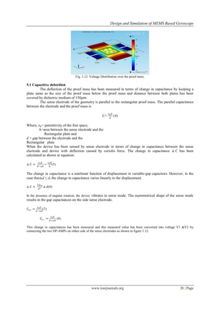
Fig. 1.13: Capacitive readout topology.
Fig. 1.14: Differential amplifier.
To detect the change in differential voltage of the pair of sensing electrodes of each side, differential amplifier has been used
as shown in above figure 1.13.
In case of this project design with parameter:
A= width*height = 415×535 (𝜇𝑚)2
𝜀0 = 8.85× 10⁻¹²
𝐹 𝑚
d= 150 𝜇𝑚
△ 𝑑 = 5.5519 𝜇𝑚
From equation (6) the change in capacitance has been calculated as△ 𝐶 = 0.145 𝑝𝐹.
Hence, sensitivity of the capacitive readout of the given geometry has been assumed as change in capacitance value i.e.
0.145 𝑝F.
Now next step is to measure current due to sense mode oscillation. This has been done by imposing a constant DC bias
voltage 𝑉𝑑𝑐 over the sense electrode with capacitance
𝐶𝑠 = 𝐶𝑠𝑒𝑛 +△ 𝐶𝑠 𝑒 𝑗𝑡𝜔 𝑠 (9)
Current becomes
𝑖 𝑠 =
𝜕
𝜕𝑡
[𝑉𝑑𝑐 𝐶𝑠(𝑡)] (10)
𝑖 𝑠 = 𝑉𝑑𝑐 𝜔𝑠 △ 𝐶𝑠 𝑒 𝑗𝑡𝜔 𝑠 (11)
Hence expected current of this topology for given geometry with𝜔𝑠 = 2 × 𝜋 × 21906.47525 ,△ 𝐶𝑠 = 0.145 𝑝𝐹𝑉𝑑𝑐 = 5 𝑉
𝑖 𝑠 = 5 × 2 × 𝜋 × 21906.47525 × 0.145 × 10−12
A
𝑖 𝑠 = 0.9979 × 10⁻⁷
A
Now voltage has been calculated by using the value of feedback resistors. Value of the feedback resistors depends on the
amplification.
△ 𝑉 = 𝐾𝑑 × 𝑖 𝑠(12)
△ 𝑉 = 0.5 𝑀Ω × 0.9979 × 10−7
A](https://image.slidesharecdn.com/c0562330-140503013315-phpapp02/85/Design-and-Simulation-of-MEMS-Based-Gyroscope-7-320.jpg)
![Design and Simulation of MEMS Based Gyroscope
www.iosrjournals.org 30 | Page
△ 𝑉 = 49.895 𝑚𝑉
Furthermore, for improving the sensitivity, overall sensing area should be increased. However, the gap between the sensing
electrode and the proof mass is the major factor that defines the capacitance sensitivity. This has been noticed from equation
(6), in which change in capacitance △ 𝐶 varies inversely to the square of the gap (d) and linear to the overlap area.
VI. Conclusions
In this paper a simulation of MEMS based gyroscope has been presented. The overview of this
geometry has been given. MEMS based gyroscope has been designed to resonate in its fundamental mode and it
has been exited by external comb drive electrode and sensed by comb sense electrode. This geometry enabled
the matching of the drive mode and sense mode frequency by varying the width of the anchors of the geometry.
The sensitivity of the given geometry for capacitive readout is 0.145 𝑝𝐹 and for the frequency of 21906.47525 Hz,
change in voltage has been calculated which is equal to 49.895 mV.
References
[1] DamrongritPiyabongkarn and Rajesh Rajamani“The Development of a MEMS Gyroscope for AbsoluteAngle Measurement”,
Department of Mechanical Engineering University of Minnesota Minneapolis, MN 55455, Proceedings of the American
ControlConference Anchorage, AK May 8-10, 2002
[2] P.J. Ngana, J.J. Koning “Design, modelling and simulation of a High Frequency MEMS Gyroscope in 1.5um SOI”, 2009(903-906),
Proceedings of the Euro sensors XXIII conference.
[3] Yoichi Mochida, Masaya Tamura “A micro-machiened vibrating rate gyroscope with independent beams for the drive and detection
modes” Yokohama Technical Center, Murata Manufacturing, 1-18-1, Hakusan, Midori-ku, Yokohama 226-0006, Japan , Sensors and
Actuators 80 (2000) 170–178
[4] Jianli Li, Jiancheng Fang, Haifeng Dong, Ye Tao “Structure design and fabrication of a novel dual-mass Resonant output
micromechanical gyroscope” MicrosystemsTechnol (2010) 16:543–552, DOI 10.1007/s00542-009-0998-8, 2010.
[5] Marcelo C. Algrain and James Quin “Accelerometer Based Line-of-Sight Stabilization Approach for Pointing andTracking Systems”
Second IEEE Conference on Control Applications, September 13 – 16, 1993 Vancouver, B.C](https://image.slidesharecdn.com/c0562330-140503013315-phpapp02/85/Design-and-Simulation-of-MEMS-Based-Gyroscope-8-320.jpg)

This document describes the design and simulation of a MEMS-based gyroscope. It includes: 1) An overview of the mechanical design of the gyroscope, which uses a square plate resonator supported by 4 anchors and driven by comb electrodes. 2) A simulation of the gyroscope in COMSOL Multiphysics to analyze performance, including eigenfrequency analysis and matching the drive and sense modes. 3) Calculation of sensitivity based on the capacitive change measured between the proof mass and detection electrode, resulting from Coriolis acceleration induced by rotation.


![[IJET-V2I1P4] Authors:Jitendra Sharad Narkhede, Dr.Kishor B. Waghulde](https://cdn.slidesharecdn.com/ss_thumbnails/ijet-v2i1p4-160427180432-thumbnail.jpg?width=640&height=640&fit=bounds)