Download to read offline


![DESIGNING MECHATRONIC SYSTEMS FOR REHABILITATION
10
References
Websites
1. List of countries by median age. In: Wikipedia [Internet]. 2017 [cited 2018 Jan
11]. Available from:
https://en.wikipedia.org/w/index.php?title=List_of_countries_by_median_age
&oldid=813536623
2. Falling (accident). In: Wikipedia [Internet]. 2018 [cited 2018 Jan 11]. Available
from:
https://en.wikipedia.org/w/index.php?title=Falling_(accident)&oldid=8189990
43
3. Products - Data Briefs - Number 199 - May 2015 [Internet]. [cited 2018 Jan
11]. Available from: https://www.cdc.gov/nchs/products/databriefs/db199.htm
4. The Human Balance System | Vestibular Disorders Association [Internet].
[cited 2018 Jan 9]. Available from: http://vestibular.org/understanding-
vestibular-disorder/human-balance-system
5. Human eye. In: Wikipedia [Internet]. 2018 [cited 2018 Jan 11]. Available from:
https://en.wikipedia.org/w/index.php?title=Human_eye&oldid=818786738
6. Vestibular system. In: Wikipedia [Internet]. 2017 [cited 2018 Jan 11]. Available
from:
https://en.wikipedia.org/w/index.php?title=Vestibular_system&oldid=812197
324
7. Somatosensory system. In: Wikipedia [Internet]. 2017 [cited 2018 Jan 11].
Available from:
https://en.wikipedia.org/w/index.php?title=Somatosensory_system&oldid=81
7766033
8. Zero moment point. In: Wikipedia [Internet]. 2016 [cited 2018 Jan 10].
Available from:
https://en.wikipedia.org/w/index.php?title=Zero_moment_point&oldid=73811
0493
9. Vukobratović M, Borovac B. Zero-moment point — thirty five years of its life.
Int J Humanoid Robot. 2004 Mar 1;01(01):157–73.
10. Goswami A. FRI point: A new gate planning tool to evaluate postural stability
of biped robots [Internet]. [cited 2018 Jan 10]. Available from:
https://www.cc.gatech.edu/fac/Chris.Atkeson/legs/kuff1c.pdf
11. Robot's Walking - Chapter 5 [Internet]. [cited 2018 Jan 11]. Available from:
http://www.diss.fu-
berlin.de/diss/servlets/MCRFileNodeServlet/FUDISS_derivate_0000000025](https://image.slidesharecdn.com/luisrita5ah12-180718002708/85/Human-Balance-Anatomy-ZMP-10-320.jpg)
![DESIGNING MECHATRONIC SYSTEMS FOR REHABILITATION
11
04/05_Kapitel5.pdf;jsessionid=BB71E0C0242031B3A6B5F4E873C63233?h
osts=
12. D A Winter. Human balance and posture control during standing and walking
[Internet]. [cited 2018 Jan 10]. Available from:
https://www.cc.gatech.edu/fac/Chris.Atkeson/legs/kuff1c.pdf](https://image.slidesharecdn.com/luisrita5ah12-180718002708/85/Human-Balance-Anatomy-ZMP-11-320.jpg)

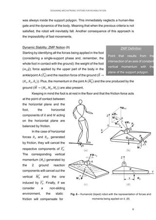
This document describes research on designing mechatronic systems for human balance rehabilitation. It discusses key human balance systems - vision, vestibular, and somatosensory systems. It then introduces the concept of Zero Moment Point (ZMP), which is important for bipedal robot balance and gait analysis. ZMP represents the point where the total momentum of a mechanism is zero. The document explains how to calculate ZMP and compares it to the Center of Pressure. Maintaining the ZMP inside the support polygon is necessary for dynamic stability. This research aims to apply insights into human balance maintenance to develop rehabilitation technologies.


![Community Finding with Applications on Phylogenetic Networks [Thesis]](https://cdn.slidesharecdn.com/ss_thumbnails/thesis-190703141252-thumbnail.jpg?width=640&height=640&fit=bounds)
![Community Finding with Applications on Phylogenetic Networks [Extended Abstract]](https://cdn.slidesharecdn.com/ss_thumbnails/extendedabstract-190703140727-thumbnail.jpg?width=640&height=640&fit=bounds)
![Community Finding with Applications on Phylogenetic Networks [Presentation]](https://cdn.slidesharecdn.com/ss_thumbnails/thesisppt-190703135818-thumbnail.jpg?width=640&height=640&fit=bounds)


