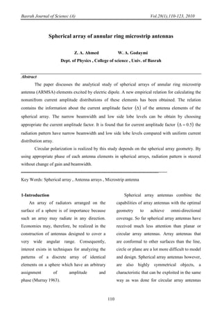
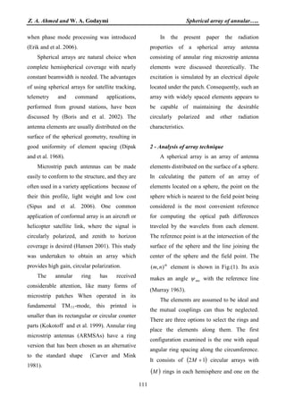
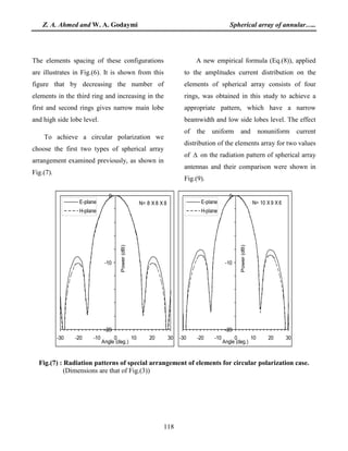
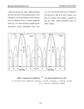
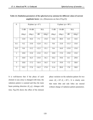
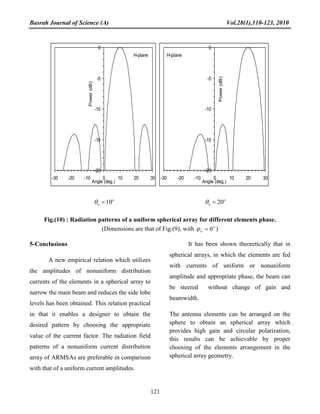
Basrah Journal of Scienec (A) Vol.28(1),110-123, 2010
110
Spherical array of annular ring microstrip antennas
Z. A. Ahmed W. A. Godaymi
Dept. of Physics , College of science , Univ. of Basrah
Abstract
The paper discusses the analytical study of spherical arrays of annular ring microstrip
antenna (ARMSA) elements excited by electric dipole. A new empirical relation for calculating the
nonunifrom current amplitude distributions of these elements has been obtained. The relation
contains the information about the current amplitude factor ( )∆ of the antenna elements of the
spherical array. The narrow beamwidth and low side lobe levels can be obtain by choosing
appropriate the current amplitude factor. It is found that for current amplitude factor ( )5.0=∆ the
radiation pattern have narrow beamwidth and low side lobe levels compared with uniform current
distribution array.
Circular polarization is realized by this study depends on the spherical array geometry. By
using appropriate phase of each antenna elements in spherical arrays, radiation pattern is steered
without change of gain and beamwidth.
--------------------------------------------------------------------------------------------------
Key Words: Spherical array , Antenna arrays , Microstrip antenna
1-Introduction
An array of radiators arranged on the
surface of a sphere is of importance because
such an array may radiate in any direction.
Economies may, therefore, be realized in the
construction of antennas designed to cover a
very wide angular range. Consequently,
interest exists in techniques for analyzing the
patterns of a discrete array of identical
elements on a sphere which have an arbitrary
assignment of amplitude and
phase (Murray 1963).
Spherical array antennas combine the
capabilities of array antennas with the optimal
geometry to achieve omni-directional
coverage. So far spherical array antennas have
received much less attention than planar or
circular array antennas. Array antennas that
are conformal to other surfaces than the line,
circle or plane are a lot more difficult to model
and design. Spherical array antennas however,
are also highly symmetrical objects, a
characteristic that can be exploited in the same
way as was done for circular array antennas
Z. A. Ahmed and W. A. Godaymi Spherical array of annular…..
111
when phase mode processing was introduced
(Erik and et al. 2006).
Spherical arrays are natural choice when
complete hemispherical coverage with nearly
constant beamwidth is needed. The advantages
of using spherical arrays for satellite tracking,
telemetry and command applications,
performed from ground stations, have been
discussed by (Boris and et al. 2002). The
antenna elements are usually distributed on the
surface of the spherical geometry, resulting in
good uniformity of element spacing (Dipak
and et al. 1968).
Microstrip patch antennas can be made
easily to conform to the structure, and they are
often used in a variety applications because of
their thin profile, light weight and low cost
(Sipus and et al. 2006). One common
application of conformal array is an aircraft or
helicopter satellite link, where the signal is
circularly polarized, and zenith to horizon
coverage is desired (Hansen 2001). This study
was undertaken to obtain an array which
provides high gain, circular polarization.
The annular ring has received
considerable attention, like many forms of
microstrip patches When operated in its
fundamental TMR
11R-mode, this printed is
smaller than its rectangular or circular counter
parts (Kokotoff and et al. 1999). Annular ring
microstrip antennas (ARMSAs) have a ring
version that has been chosen as an alternative
to the standard shape (Carver and Mink
1981).
In the present paper the radiation
properties of a spherical array antenna
consisting of annular ring microstrip antenna
elements were discussed theoretically. The
excitation is simulated by an electrical dipole
located under the patch. Consequently, such an
array with widely spaced elements appears to
be capable of maintaining the desirable
circularly polarized and other radiation
characteristics.
2 - Analysis of array technique
A spherical array is an array of antenna
elements distributed on the surface of a sphere.
In calculating the pattern of an array of
elements located on a sphere, the point on the
sphere which is nearest to the field point being
considered is the most convenient reference
for computing the optical path differences
traveled by the wavelets from each element.
The reference point is at the intersection of the
surface of the sphere and the line joining the
center of the sphere and the field point. The
th
nm ),( element is shown in Fig.(1). Its axis
makes an angle mnψ with the reference line
(Murray 1963).
The elements are assumed to be ideal and
the mutual couplings can thus be neglected.
There are three options to select the rings and
place the elements along them. The first
configuration examined is the one with equal
angular ring spacing along the circumference.
It consists of ( )12 +M circular arrays with
( )M rings in each hemisphere and one on the
Basrah Journal of Scienec (A) Vol.28(1),110-123, 2010
112
equator. The spacing ( )d of the adjacent rings
along the sphere circumference is uniform and
equal to :-
)1(2 +
=
M
R
d
π
………(1)
Fig.(1) : Spherical polar coordinate system and direction angles of spherical arrays.
There are mN elements equally distributed in
the th
m ring. The radius of the th
m ring, as
shown in Fig.(2), is :-
mm RR θsin= ………(2)
Where R is the radius of the sphere. The
spherical coordinates of the th
nm ),( element
are given by ( )mmR φθ ,, with :-
,
1
1
2






+
−+
=
M
mM
m
π
θ MMMMm ),1(,......,0),......,1(, −+−−= ………(3)
,
2
m
mn
N
nπ
φ = mNn ,......,2,1= ………(4)
Since mN in each ring can be different, the
element spacing may not be uniform.
The spacing of the adjacent elements
(ARMSAs) along the circumference of the
th
m ring is :-
Field point
The main beam
direction
oα
y
x
z
γ
α
β
r
oφ
oθ
oβ th
nm ),(
Basrah Journal of Science (A) Vol.28(1),110-123, 2010
113
( )
m
mm
N
gNR
d
−
=
π2
………(5)
Fig.(2) : Spherical array geometry .
Where g is the radius of the ground plane of
the ARMSA. The far electric field at the
observation point ( )φθ,,rP is (Wolf 1966) :-
( ) ( )∑ ∑−= =
−
=
M
Mm
N
n
jkR
nmn
jkr m
mn
efa
r
e
E
1
cos
,, ψ
φθφθ ……(6)
where k is the propagation constant for free
space, ( )φθ,nf describes the variation of the
element pattern in space, mna is a complex
number representing the magnitude and phase
with which the th
nm ),( element is excited
relative to a common reference for all
elements in the array and can be represented
as :
),( oomnoj
mnmn eAa φθζ
= ………(7)
th
nm ),(
z
R
md
x
y
d
mθ
mnφ
mm RR θsin=
m=0
m=1
m=2
Z. A. Ahmed and W. A. Godaymi Spherical array of annular…..
114
Where mnA can be fitted for the current
distribution on the elements and calculated
from an empirical formula obtained in this
work :
0,
0,
0,
0
0
0
〉
∆
=
〈∆−=
==
mfor
m
A
A
mforAmA
mforAA
n
mn
nmn
nmn ……(8)
Here ∆ is a current amplitude factor, and
mnoζ is the phase of the th
nm ),( element and
selected by :-
mnomno kR ψζ cos= ………(9)
The subscript of the angle θ and φ is
selected to the direction of the main beam of
the radiation pattern. and mnψ is the angle
between the th
nm ),( element axis and the
field point , whose direction cosines are
γβα cos,cos,cos , and given by:
mnmnmnmn γγββααψ coscoscoscoscoscoscos ++= ……(10a)
mnmnmnmn θθφφθθψ coscos)cos(sinsincos +−= ……(10b)
3 - Elements of the array
The element considered in this analysis is the
ARMSA. This antenna consists of a
conducting patch of radius (a) and thickness
(at) separated from the ground plane of radius
(g) and thickness (gt
)(ε
) by a dielectric material
of thickness (h) and dielectric constant . In
this work the patch, dielectric and the ground
plane surfaces are assumed to be rotationally
symmetric to represent BoRs, as shown in
Fig.(3). This antenna has the dimensions :-
Ratio (Rab 1.2=a/b) =
Ground plane radius (g) = 11.0 (cm)
Ground plane thickness (gt 0.179 (cm)) =
Patch thickness (at 0.179 (cm)) =
Thickness of dielectric material (h) = 0.20 (cm)
Dielectric constant )(ε = 2.32
Frequency (fr 1.67 (GHz)) =
Feed location ),( ff φρ = (2.00 cm , 0.0o
)
Basrah Journal of Science (A) Vol.28(1),110-123, 2010
115
Fig.(3) : Geometry of the annular ring microstrip antenna .
A rigorous analysis of the problems begins with
the application of the equivalence principle that
introduce an unknown electric current density
on the conducting surface, and both unknowns
equivalent electric and magnetic surface current
densities on the dielectric surface. These
currents densities satisfy the integral equations.
The formulation of the radiation problems is
based on the combined field integral equation
(CFIE). This formulation coupled with the
method of moments (MoMs), as a numerical
solution for the CFIE, to translate them to a set
of linear equations. The excitation is simulated
by an electrical dipole located under the patch.
The patch size is selected to excite the TM11
Fig.(4) shows that the performance of
spherical array in H-plane is preferable in
comparison with circular array. In this figure
the spherical array has three rings, the elements
number in the 0
-
mode. The plane of the ARMSAs were placed
perpendicular to the z- axis of the sphere.
4-Results and discussion
th
ring is 4 and 5, respectively,
while in the ±1th
rings is two. It is clearly
shown that the first side lobe level and the
beamwidth in the spherical array is less than in
the circular array.
z
b
Ground plane
ε
gt
g
h
at
y
Patch
Dielectric substrate
x
a
Z. A. Ahmed and W. A. Godaymi Spherical array of annular…..
116
(a) (b)
Fig.( 4) : Radiation patterns of a uniform spherical and circular arrays a point source elements
with 2/λ=R (a) (Spherical )2,4( 10 == ±NN ,Circular )8( =N ),
(b) (Spherical )2,5( 10 == ±NN Nm=5X2 ,Circular )9( =N )
The investigation also was done to study
the effect of changing the radius of spherical
array of ARMSAs elements on the radiation
patterns. Fig.(5) shows that the sphere radius
has significant effect on the radiation pattern
parameters in the principle planes. As a result,
increasing the radius of sphere increases the
side lobe levels and narrow the beamwidth.
It may be desirable to study the effects of
the contributions of the elements in the
different rings on the radiation patterns of the
spherical array. Three different types of
spherical array configurations are examined.
These arrays have three rings and 40 elements
in each. The first configuration has 8 elements
in each ring, while the second and third types
have the number of elements
)6,9,10( 210 === ±± NNN and
)4,10,12( 210 === ±± NNN ,respectively.
H-plane
-40
-30
-20
-10
0
-90 -60 -30 0 30 60 90
Angle (deg.)
Power(dB)
Spherical
Cirular
H-plane
-40
-30
-20
-10
0
-90 -60 -30 0 30 60 90
Angle (deg.)
Power(dB)
Spherical
Cirular
Basrah Journal of Science (A) Vol.28(1),110-123, 2010
117
Fig.( 5) : Radiation patterns of a uniform spherical array )0( =m of five ARMSA elements with
)27.1,5.1(and)64.0,0.1(),016.0,5.0( λλλλλλ ====== dRdRdR .
Fig.(6) : Radiation patterns of a uniform spherical array of arrangement:
)0.1,17.0(),73.1,75.0(),0.2,96.0(888 221100 λλλλλλ ======××= ±±±± RdRdRdN
)0.1,43.0(),73.1,60.0(),0.2,64.0(6910 221100 λλλλλλ ======××= ±±±± RdRdRdN
)0.1,96.0(),73.1,48.0(),0.2,43.0(41012 221100 λλλλλλ ======××= ±±±± RdRdRdN
H-plane
-40
-30
-20
-10
0
-90 -60 -30 0 30 60 90
Angle (deg.)
Power(dB)
R=0.5
R=1.0
R=1.5
E-plane
-40
-30
-20
-10
0
-90 -60 -30 0 30 60 90
Angle (deg.)
Power(dB)
R=0.5
R=1.0
R=1.5
H-plane
-20
-10
0
-30 -20 -10 0 10 20 30
Angle (deg.)
Power(dB)
N= 8 x 8 x8
N= 10 x 9 x 6
N= 12 x 10 x 4
E-plane
-20
-10
0
-30 -20 -10 0 10 20 30
Angle (deg.)
Power(dB)
N= 8 x 8 x8
N= 10 x 9 x 6
N= 12 x 10 x 4
Z. A. Ahmed and W. A. Godaymi Spherical array of annular…..
118
The elements spacing of these configurations
are illustrates in Fig.(6). It is shown from this
figure that by decreasing the number of
elements in the third ring and increasing in the
first and second rings gives narrow main lobe
and high side lobe level.
To achieve a circular polarization we
choose the first two types of spherical array
arrangement examined previously, as shown in
Fig.(7).
A new empirical formula (Eq.(8)), applied
to the amplitudes current distribution on the
elements of spherical array consists of four
rings, was obtained in this study to achieve a
appropriate pattern, which have a narrow
beamwidth and low side lobes level. The effect
of the uniform and nonuniform current
distribution of the elements array for two values
of ∆ on the radiation pattern of spherical array
antennas and their comparison were shown in
Fig.(9).
Fig.(7) : Radiation patterns of special arrangement of elements for circular polarization case.
(Dimensions are that of Fig.(3))
N= 8 X 8 X 8
-20
-10
0
-30 -20 -10 0 10 20 30
Angle (deg.)
Power(dB)
E-plane
H-plane
N= 10 X 9 X 6
-20
-10
0
-30 -20 -10 0 10 20 30
Angle (deg.)
Power(dB)
E-plane
H-plane
Basrah Journal of Science (A) Vol.28(1),110-123, 2010
119
Table (1) indicates the -3dB, -10dB beamwidth
and first side level in the principle planes of the
nonuniform current distribution of the elements
array for different values of current amplitude
factor )(∆ . It is observed that by employing the
nonuniform current distribution array with
)5.0( =∆ , the first side lobe level is reduced by
(5.4 dB and 6.7 dB) in H- and E- planes, over
that of a uniform array patterns, respectively,
and the -3dB, -10dB beamwidth reduce by
about 3 degree
Fig.(9) : Comparison of radiation patterns of a uniform spherical array with :
)98.0(),95.0,39.2(,
)76.1,16.2(),3.2,2.1(),5.2,69.0(24812
23
221100
λλλ
λλλλλλ
===
======×××=
±±
±±±±
dRd
RdRdRdN
H-plane
-20
-10
0
-30 -20 -10 0 10 20 30
Angle (deg.)
Power(dB)
uniform
delta=0.5
delta=7.0
E-plane
-20
-10
0
-30 -20 -10 0 10 20 30
Angle (deg.)
Power(dB)
uniform
delta=0.5
delta=7.0
∆
∆∆
∆∆
Z. A. Ahmed and W. A. Godaymi Spherical array of annular…..
120
Table (1): Radiation parameters of the spherical array antenna for different values of current
amplitude factor )(∆ . (Dimensions are that of Fig.(9))
∆ H-plane )0( o
=ϕ E-plane )90( o
=ϕ
-3 dB
(deg.)
-10 dB
(deg.)
SLL -3 dB
(deg.)
-10 dB
(deg.)
SLL
dB (deg.) dB (deg.)
--- 12.0 18.4 -7.1 15.0 12.6 20.0 -8.3 14.8
0.1 9.2 15.0 -12.0 15.1 9.6 15.8 -13.3 15.0
0.5 9.0 15.2 -12.5 15.1 9.6 16.0 -15.0 15.0
1 10.0 15.8 -13.8 15.2 10.0 17.0 -19.0 15.0
3 10.0 16.5 -15.8 16.1 10.2 19.0 -8.1 29.0
5 10.0 17.2 -16.4 16.5 11.4 19.8 -7.2 30.0
7 10.2 17.8 -16.5 17.0 11.6 20.0 -7.0 30.0
It is well-known that if the phase of each
element in any array is changed with time, the
radiation pattern is scanned and thus the main
beam pointing direction ),( oo φθ changes with
time. Fig.(10) shows the effect of the element
phase variation on the radiation pattern for two
cases )20,10( o
o
o
o == θθ . It is clearly seen
that main lobe and side lobes are steered
without change of radiation pattern parameters.
Basrah Journal of Science (A) Vol.28(1),110-123, 2010
121
o
o 10=θ o
o 20=θ
Fig.(10) : Radiation patterns of a uniform spherical array for different elements phase.
(Dimensions are that of Fig.(9), with o
o 0=ϕ )
5-Conclusions
A new empirical relation which utilizes
the amplitudes of nonuniform distribution
currents of the elements in a spherical array to
narrow the main beam and reduces the side lobe
levels has been obtained. This relation practical
in that it enables a designer to obtain the
desired pattern by choosing the appropriate
value of the current factor. The radiation field
patterns of a nonuniform current distribution
array of ARMSAs are preferable in comparison
with that of a uniform current amplitudes.
It has been shown theoretically that in
spherical arrays, in which the elements are fed
with currents of uniform or nonuniform
amplitude and appropriate phase, the beam can
be steered without change of gain and
beamwidth.
The antenna elements can be arranged on the
sphere to obtain an spherical array which
provides high gain and circular polarization,
this results can be achievable by proper
choosing of the elements arrangement in the
spherical array geometry.
H-plane
-20
-15
-10
-5
0
-30 -20 -10 0 10 20 30
Angle (deg.)
Power(dB)
H-plane
-20
-15
-10
-5
0
-30 -20 -10 0 10 20 30
Angle (deg.)
Power(dB)
Z. A. Ahmed and W. A. Godaymi Spherical array of annular…..
122
5-References
Boris, T., John, T., and Shiang, L. "A geodesic
sphere phased array antenna for satellite control
and communication" Air force research
laboratory,
E-mail: boris-tomasic@hanscom.af.mil.
Carver, K. R. and Mink, J. W., "Microstrip
antenna technology", IEEE Trans. Anten. and
Propag. Vol. AP-29, No; 1, pp. 2-24, 1981.
Dipak, L. S., Thomas, M. S., and Ronal, W. L.,
"Radiation characteristics of a spherical array
of circularly polarized elements" ,IEEE Trans.
Anten. And Propag., Vol. AP-16, No. 1, pp. 2-7
, January, 1968.
Erik De, W., Leonidos, M., Kin-Fai T., Paul,
B., and Hugh, G., "Design and
development of a spherical array antenna" 6-10
November 2006 (ESA SP-626,October 2006).
Hansen, R. C., "Phased array antennas", Jonh
Wiely and Sons, Inc., New York, 2001.
Kokotoff, D. M., Aberle, J. T. and Waterhouse,
R. B., “Rigorous analysis of probe-fed printed
annular ring antennas" , IEEE Trans. Anten.
and Propag. Vol. 47, No;2, pp. 384-388, 1999.
Murray, H., "Conventions for the analysis of
spherical arrays", IEEE Trans.Anten. and
Propag., pp. 390-393, July, 1963.
Sipus, Z., Burum, N., Skokic, S. and Kildal, P.-
S., " Analysis of spherical arrays of microstrip
antennas using moment method in spectral
domain", IEE Proc.-Microw. Antennas Propag.,
Vol. 153, No. 6, December 2006
Wolf, E. A. "Antenna analysis", Wiely, New
York,1966
Basrah Journal of Science (A) Vol.28(1),110-123, 2010
123
‫ﺣﻠﻘﻴﺔ‬ ‫ﺷﺮﻳﻄﻴﺔ‬ ‫ﻫﻮﺍﺋﻴﺎﺕ‬ ‫ﻣﻦ‬ ‫ﺍﻟﻤﻜﻮﻧﺔ‬ ‫ﺍﻟﻜﺮﻭﻳﺔ‬ ‫ﺍﻟﻤﺼﻔﻮﻓﺔ‬
‫ﺍﺣﻤﺪ‬ ‫ﺍﷲ‬ ‫ﻋﺒﺪ‬ ‫ﺯﻛﻲ‬ .‫ﺃ.ﺩ‬‫ﺍﻟﻠﻄﻴﻒ‬ ‫ﻋﺒﺪ‬ ‫ﻭﺍﺋﻞ‬ .‫ﻡ.ﺩ‬‫ﻙ‬‫ﺩﻱ‬‫ﻣﻲ‬
‫ﺍﻟﻔﻴﺰﻳﺎء‬ ‫ﻗﺴﻢ‬–‫ﺍﻟﻌﻠﻮﻡ‬ ‫ﻛﻠﻴﺔ‬–‫ﺍﻟﺒﺼﺮﺓ‬ ‫ﺟﺎﻣﻌﺔ‬
‫ﺍﻟﺨﻼﺻﺔ‬
.‫ﻛﻬﺮﺑﺎﺋﻲ‬ ‫ﻗﻄﺐ‬ ‫ﺑﺜﺎﻧﻲ‬ ‫ﻣﻐﺬﺍ‬ ‫ﺣﻠﻘﻲ‬ ‫ﺷﺮﻳﻄﻲ‬ ‫ﻫﻮﺍﺋﻲ‬ ‫ﻣﻦ‬ ‫ﻣﻜﻮﻧﺔ‬ ‫ﻋﻨﺎﺻﺮﻫﺎ‬ ‫ﺍﻟﺘﻲ‬ ‫ﺍﻟﻜﺮﻭﻳﺔ‬ ‫ﻟﻠﻤﺼﻔﻮﻓﺎﺕ‬ ‫ﻧﻈﺮﻳﺔ‬ ‫ﺩﺭﺍﺳﺔ‬ ‫ﺍﻟﺒﺤﺚ‬ ‫ﻳﺘﻨﺎﻭﻝ‬
‫ﺗﺘﻀﻤﻦ‬ ‫ﺍﻟﻌﻼﻗﺔ‬ ‫ﻫﺬﻩ‬ .‫ﺍﻟﻤﺼﻔﻮﻓﺔ‬ ‫ﻋﻨﺎﺻﺮ‬ ‫ﻟﺘﻴﺎﺭ‬ ‫ﺍﻟﻤﻨﺘﻈﻤﺔ‬ ‫ﻏﻴﺮ‬ ‫ﺍﻟﺴﻌﺎﺕ‬ ‫ﺗﻮﺯﻳﻊ‬ ‫ﻟﺤﺴﺎﺏ‬ ‫ﺟﺪﻳﺪﺓ‬ ‫ﺗﺠﺮﻳﺒﻴﺔ‬ ‫ﻋﻼﻗﺔ‬ ‫ﺇﻟﻰ‬ ‫ﺍﻟﺘﻮﺻﻞ‬ ‫ﺍﻟﻌﻤﻞ‬ ‫ﻫﺬﺍ‬ ‫ﻓﻲ‬ ‫ﺗﻢ‬
‫ﺍﻟﺘﻴﺎﺭ‬ ‫ﺳﻌﺔ‬ ‫ﻋﺎﻣﻞ‬ ‫ﺣﻮﻝ‬ ‫ﻣﻌﻠﻮﻣﺎﺕ‬( )∆‫ﻛﺎﻥ‬ .‫ﻭﺍﻃﺌﺔ‬ ‫ﺟﺎﻧﺒﻴﺔ‬ ‫ﻓﻠﻘﺔ‬ ‫ﻭﻣﺴﺘﻮﻯ‬ ‫ﺿﻴﻘﺔ‬ ‫ﺭﺋﻴﺴﺔ‬ ‫ﻓﻠﻘﺔ‬ ‫ﻋﻠﻰ‬ ‫ﺍﻟﺤﺼﻮﻝ‬ ‫ﻳﻤﻜﻦ‬ ‫ﻟﻪ‬ ‫ﻣﻨﺎﺳﺐ‬ ‫ﺑﺎﺧﺘﻴﺎﺭ‬ ‫ﻭﺍﻟﺘﻲ‬ .
‫ﻗﻴﻤﺔ‬ ‫ﺑﺄﻥ‬ ‫ﻋﻠﻴﻬﺎ‬ ‫ﺣﺼﻠﻨﺎ‬ ‫ﺍﻟﺘﻲ‬ ‫ﺍﻟﻨﺘﺎﺋﺞ‬ ‫ﻣﻦ‬ ً‫ﻭﺍﺿﺤﺎ‬)5.0( =∆‫ﺍﻟﺠﺎﻧﺒﻴﺔ‬ ‫ﻟﻠﻔﻠﻖ‬ ‫ﻭﺍﻃﺊ‬ ‫ﻭﻣﺴﺘﻮﻯ‬ ‫ﺿﻴﻘﺔ‬ ‫ﺭﺋﻴﺴﺔ‬ ‫ﻓﻠﻘﺔ‬ ‫ﺫﻭ‬ ‫ﺇﺷﻌﺎﻉ‬ ‫ﻫﻴﻜﻞ‬ ‫ﻋﻨﻬﺎ‬ ‫ﻳﻨﺘﺞ‬
‫ﻓﻲ‬ ‫ﺗﺤﻘﻴﻘﻪ‬ ‫ﺗﻢ‬ ‫ﺍﻟﺪﺍﺋﺮﻱ‬ ‫ﺍﻻﺳﺘﻘﻄﺎﺏ‬ .‫ﻣﻨﺘﻈﻤﺔ‬ ‫ﺗﻴﺎﺭ‬ ‫ﺳﻌﺎﺕ‬ ‫ﺗﻤﺘﻠﻚ‬ ‫ﻋﻨﺎﺻﺮﻫﺎ‬ ‫ﺍﻟﺘﻲ‬ ‫ﺍﻟﻜﺮﻭﻳﺔ‬ ‫ﺍﻟﻤﺼﻔﻮﻓﺔ‬ ‫ﻋﻦ‬ ‫ﺍﻟﻨﺎﺗﺠﺔ‬ ‫ﺍﻟﻤﻌﺎﻣﻼﺕ‬ ‫ﺗﻠﻚ‬ ‫ﻣﻊ‬ ‫ﻣﻘﺎﺭﻧﺔ‬
‫ﻓﻲ‬ ‫ﻋﻨﺼﺮ‬ ‫ﻟﻜﻞ‬ ‫ﻟﻠﻄﻮﺭ‬ ‫ﻣﻨﺎﺳﺐ‬ ‫ﻭﺑﺎﺧﺘﻴﺎﺭ‬ ً‫ﻭﺃﺧﻴﺮﺍ‬ .‫ﺍﻟﻜﺮﻭﻳﺔ‬ ‫ﺍﻟﻤﺼﻔﻮﻓﺔ‬ ‫ﻟﻌﻨﺎﺻﺮ‬ ‫ﺍﻟﻬﻨﺪﺳﻲ‬ ‫ﺍﻟﺘﻮﺯﻳﻊ‬ ‫ﻋﻠﻰ‬ ‫ﺑﺎﻻﻋﺘﻤﺎﺩ‬ ‫ﻭﺫﻟﻚ‬ ‫ﺍﻟﺪﺭﺍﺳﺔ‬ ‫ﻫﺬﻩ‬
.‫ﺍﻹﺷﻌﺎﻉ‬ ‫ﻭﻋﺮﺽ‬ ‫ﺍﻻﺗﺠﺎﻫﻴﺔ‬ ‫ﻓﻲ‬ ‫ﺗﻐﻴﻴﺮ‬ ‫ﺩﻭﻥ‬ ‫ﺍﻹﺷﻌﺎﻉ‬ ‫ﻫﻴﻜﻞ‬ ‫ﺗﻮﺟﻴﻪ‬ ‫ﻋﻠﻰ‬ ‫ﺍﻟﺤﺼﻮﻝ‬ ‫ﺗﻢ‬ ‫ﺍﻟﻤﺼﻔﻮﻓﺔ‬

Spherical array of annular ring microstrip antennas

  • 1.
    Basrah Journal ofScienec (A) Vol.28(1),110-123, 2010 110 Spherical array of annular ring microstrip antennas Z. A. Ahmed W. A. Godaymi Dept. of Physics , College of science , Univ. of Basrah Abstract The paper discusses the analytical study of spherical arrays of annular ring microstrip antenna (ARMSA) elements excited by electric dipole. A new empirical relation for calculating the nonunifrom current amplitude distributions of these elements has been obtained. The relation contains the information about the current amplitude factor ( )∆ of the antenna elements of the spherical array. The narrow beamwidth and low side lobe levels can be obtain by choosing appropriate the current amplitude factor. It is found that for current amplitude factor ( )5.0=∆ the radiation pattern have narrow beamwidth and low side lobe levels compared with uniform current distribution array. Circular polarization is realized by this study depends on the spherical array geometry. By using appropriate phase of each antenna elements in spherical arrays, radiation pattern is steered without change of gain and beamwidth. -------------------------------------------------------------------------------------------------- Key Words: Spherical array , Antenna arrays , Microstrip antenna 1-Introduction An array of radiators arranged on the surface of a sphere is of importance because such an array may radiate in any direction. Economies may, therefore, be realized in the construction of antennas designed to cover a very wide angular range. Consequently, interest exists in techniques for analyzing the patterns of a discrete array of identical elements on a sphere which have an arbitrary assignment of amplitude and phase (Murray 1963). Spherical array antennas combine the capabilities of array antennas with the optimal geometry to achieve omni-directional coverage. So far spherical array antennas have received much less attention than planar or circular array antennas. Array antennas that are conformal to other surfaces than the line, circle or plane are a lot more difficult to model and design. Spherical array antennas however, are also highly symmetrical objects, a characteristic that can be exploited in the same way as was done for circular array antennas
  • 2.
    Z. A. Ahmedand W. A. Godaymi Spherical array of annular….. 111 when phase mode processing was introduced (Erik and et al. 2006). Spherical arrays are natural choice when complete hemispherical coverage with nearly constant beamwidth is needed. The advantages of using spherical arrays for satellite tracking, telemetry and command applications, performed from ground stations, have been discussed by (Boris and et al. 2002). The antenna elements are usually distributed on the surface of the spherical geometry, resulting in good uniformity of element spacing (Dipak and et al. 1968). Microstrip patch antennas can be made easily to conform to the structure, and they are often used in a variety applications because of their thin profile, light weight and low cost (Sipus and et al. 2006). One common application of conformal array is an aircraft or helicopter satellite link, where the signal is circularly polarized, and zenith to horizon coverage is desired (Hansen 2001). This study was undertaken to obtain an array which provides high gain, circular polarization. The annular ring has received considerable attention, like many forms of microstrip patches When operated in its fundamental TMR 11R-mode, this printed is smaller than its rectangular or circular counter parts (Kokotoff and et al. 1999). Annular ring microstrip antennas (ARMSAs) have a ring version that has been chosen as an alternative to the standard shape (Carver and Mink 1981). In the present paper the radiation properties of a spherical array antenna consisting of annular ring microstrip antenna elements were discussed theoretically. The excitation is simulated by an electrical dipole located under the patch. Consequently, such an array with widely spaced elements appears to be capable of maintaining the desirable circularly polarized and other radiation characteristics. 2 - Analysis of array technique A spherical array is an array of antenna elements distributed on the surface of a sphere. In calculating the pattern of an array of elements located on a sphere, the point on the sphere which is nearest to the field point being considered is the most convenient reference for computing the optical path differences traveled by the wavelets from each element. The reference point is at the intersection of the surface of the sphere and the line joining the center of the sphere and the field point. The th nm ),( element is shown in Fig.(1). Its axis makes an angle mnψ with the reference line (Murray 1963). The elements are assumed to be ideal and the mutual couplings can thus be neglected. There are three options to select the rings and place the elements along them. The first configuration examined is the one with equal angular ring spacing along the circumference. It consists of ( )12 +M circular arrays with ( )M rings in each hemisphere and one on the
  • 3.
    Basrah Journal ofScienec (A) Vol.28(1),110-123, 2010 112 equator. The spacing ( )d of the adjacent rings along the sphere circumference is uniform and equal to :- )1(2 + = M R d π ………(1) Fig.(1) : Spherical polar coordinate system and direction angles of spherical arrays. There are mN elements equally distributed in the th m ring. The radius of the th m ring, as shown in Fig.(2), is :- mm RR θsin= ………(2) Where R is the radius of the sphere. The spherical coordinates of the th nm ),( element are given by ( )mmR φθ ,, with :- , 1 1 2       + −+ = M mM m π θ MMMMm ),1(,......,0),......,1(, −+−−= ………(3) , 2 m mn N nπ φ = mNn ,......,2,1= ………(4) Since mN in each ring can be different, the element spacing may not be uniform. The spacing of the adjacent elements (ARMSAs) along the circumference of the th m ring is :- Field point The main beam direction oα y x z γ α β r oφ oθ oβ th nm ),(
  • 4.
    Basrah Journal ofScience (A) Vol.28(1),110-123, 2010 113 ( ) m mm N gNR d − = π2 ………(5) Fig.(2) : Spherical array geometry . Where g is the radius of the ground plane of the ARMSA. The far electric field at the observation point ( )φθ,,rP is (Wolf 1966) :- ( ) ( )∑ ∑−= = − = M Mm N n jkR nmn jkr m mn efa r e E 1 cos ,, ψ φθφθ ……(6) where k is the propagation constant for free space, ( )φθ,nf describes the variation of the element pattern in space, mna is a complex number representing the magnitude and phase with which the th nm ),( element is excited relative to a common reference for all elements in the array and can be represented as : ),( oomnoj mnmn eAa φθζ = ………(7) th nm ),( z R md x y d mθ mnφ mm RR θsin= m=0 m=1 m=2
  • 5.
    Z. A. Ahmedand W. A. Godaymi Spherical array of annular….. 114 Where mnA can be fitted for the current distribution on the elements and calculated from an empirical formula obtained in this work : 0, 0, 0, 0 0 0 〉 ∆ = 〈∆−= == mfor m A A mforAmA mforAA n mn nmn nmn ……(8) Here ∆ is a current amplitude factor, and mnoζ is the phase of the th nm ),( element and selected by :- mnomno kR ψζ cos= ………(9) The subscript of the angle θ and φ is selected to the direction of the main beam of the radiation pattern. and mnψ is the angle between the th nm ),( element axis and the field point , whose direction cosines are γβα cos,cos,cos , and given by: mnmnmnmn γγββααψ coscoscoscoscoscoscos ++= ……(10a) mnmnmnmn θθφφθθψ coscos)cos(sinsincos +−= ……(10b) 3 - Elements of the array The element considered in this analysis is the ARMSA. This antenna consists of a conducting patch of radius (a) and thickness (at) separated from the ground plane of radius (g) and thickness (gt )(ε ) by a dielectric material of thickness (h) and dielectric constant . In this work the patch, dielectric and the ground plane surfaces are assumed to be rotationally symmetric to represent BoRs, as shown in Fig.(3). This antenna has the dimensions :- Ratio (Rab 1.2=a/b) = Ground plane radius (g) = 11.0 (cm) Ground plane thickness (gt 0.179 (cm)) = Patch thickness (at 0.179 (cm)) = Thickness of dielectric material (h) = 0.20 (cm) Dielectric constant )(ε = 2.32 Frequency (fr 1.67 (GHz)) = Feed location ),( ff φρ = (2.00 cm , 0.0o )
  • 6.
    Basrah Journal ofScience (A) Vol.28(1),110-123, 2010 115 Fig.(3) : Geometry of the annular ring microstrip antenna . A rigorous analysis of the problems begins with the application of the equivalence principle that introduce an unknown electric current density on the conducting surface, and both unknowns equivalent electric and magnetic surface current densities on the dielectric surface. These currents densities satisfy the integral equations. The formulation of the radiation problems is based on the combined field integral equation (CFIE). This formulation coupled with the method of moments (MoMs), as a numerical solution for the CFIE, to translate them to a set of linear equations. The excitation is simulated by an electrical dipole located under the patch. The patch size is selected to excite the TM11 Fig.(4) shows that the performance of spherical array in H-plane is preferable in comparison with circular array. In this figure the spherical array has three rings, the elements number in the 0 - mode. The plane of the ARMSAs were placed perpendicular to the z- axis of the sphere. 4-Results and discussion th ring is 4 and 5, respectively, while in the ±1th rings is two. It is clearly shown that the first side lobe level and the beamwidth in the spherical array is less than in the circular array. z b Ground plane ε gt g h at y Patch Dielectric substrate x a
  • 7.
    Z. A. Ahmedand W. A. Godaymi Spherical array of annular….. 116 (a) (b) Fig.( 4) : Radiation patterns of a uniform spherical and circular arrays a point source elements with 2/λ=R (a) (Spherical )2,4( 10 == ±NN ,Circular )8( =N ), (b) (Spherical )2,5( 10 == ±NN Nm=5X2 ,Circular )9( =N ) The investigation also was done to study the effect of changing the radius of spherical array of ARMSAs elements on the radiation patterns. Fig.(5) shows that the sphere radius has significant effect on the radiation pattern parameters in the principle planes. As a result, increasing the radius of sphere increases the side lobe levels and narrow the beamwidth. It may be desirable to study the effects of the contributions of the elements in the different rings on the radiation patterns of the spherical array. Three different types of spherical array configurations are examined. These arrays have three rings and 40 elements in each. The first configuration has 8 elements in each ring, while the second and third types have the number of elements )6,9,10( 210 === ±± NNN and )4,10,12( 210 === ±± NNN ,respectively. H-plane -40 -30 -20 -10 0 -90 -60 -30 0 30 60 90 Angle (deg.) Power(dB) Spherical Cirular H-plane -40 -30 -20 -10 0 -90 -60 -30 0 30 60 90 Angle (deg.) Power(dB) Spherical Cirular
  • 8.
    Basrah Journal ofScience (A) Vol.28(1),110-123, 2010 117 Fig.( 5) : Radiation patterns of a uniform spherical array )0( =m of five ARMSA elements with )27.1,5.1(and)64.0,0.1(),016.0,5.0( λλλλλλ ====== dRdRdR . Fig.(6) : Radiation patterns of a uniform spherical array of arrangement: )0.1,17.0(),73.1,75.0(),0.2,96.0(888 221100 λλλλλλ ======××= ±±±± RdRdRdN )0.1,43.0(),73.1,60.0(),0.2,64.0(6910 221100 λλλλλλ ======××= ±±±± RdRdRdN )0.1,96.0(),73.1,48.0(),0.2,43.0(41012 221100 λλλλλλ ======××= ±±±± RdRdRdN H-plane -40 -30 -20 -10 0 -90 -60 -30 0 30 60 90 Angle (deg.) Power(dB) R=0.5 R=1.0 R=1.5 E-plane -40 -30 -20 -10 0 -90 -60 -30 0 30 60 90 Angle (deg.) Power(dB) R=0.5 R=1.0 R=1.5 H-plane -20 -10 0 -30 -20 -10 0 10 20 30 Angle (deg.) Power(dB) N= 8 x 8 x8 N= 10 x 9 x 6 N= 12 x 10 x 4 E-plane -20 -10 0 -30 -20 -10 0 10 20 30 Angle (deg.) Power(dB) N= 8 x 8 x8 N= 10 x 9 x 6 N= 12 x 10 x 4
  • 9.
    Z. A. Ahmedand W. A. Godaymi Spherical array of annular….. 118 The elements spacing of these configurations are illustrates in Fig.(6). It is shown from this figure that by decreasing the number of elements in the third ring and increasing in the first and second rings gives narrow main lobe and high side lobe level. To achieve a circular polarization we choose the first two types of spherical array arrangement examined previously, as shown in Fig.(7). A new empirical formula (Eq.(8)), applied to the amplitudes current distribution on the elements of spherical array consists of four rings, was obtained in this study to achieve a appropriate pattern, which have a narrow beamwidth and low side lobes level. The effect of the uniform and nonuniform current distribution of the elements array for two values of ∆ on the radiation pattern of spherical array antennas and their comparison were shown in Fig.(9). Fig.(7) : Radiation patterns of special arrangement of elements for circular polarization case. (Dimensions are that of Fig.(3)) N= 8 X 8 X 8 -20 -10 0 -30 -20 -10 0 10 20 30 Angle (deg.) Power(dB) E-plane H-plane N= 10 X 9 X 6 -20 -10 0 -30 -20 -10 0 10 20 30 Angle (deg.) Power(dB) E-plane H-plane
  • 10.
    Basrah Journal ofScience (A) Vol.28(1),110-123, 2010 119 Table (1) indicates the -3dB, -10dB beamwidth and first side level in the principle planes of the nonuniform current distribution of the elements array for different values of current amplitude factor )(∆ . It is observed that by employing the nonuniform current distribution array with )5.0( =∆ , the first side lobe level is reduced by (5.4 dB and 6.7 dB) in H- and E- planes, over that of a uniform array patterns, respectively, and the -3dB, -10dB beamwidth reduce by about 3 degree Fig.(9) : Comparison of radiation patterns of a uniform spherical array with : )98.0(),95.0,39.2(, )76.1,16.2(),3.2,2.1(),5.2,69.0(24812 23 221100 λλλ λλλλλλ === ======×××= ±± ±±±± dRd RdRdRdN H-plane -20 -10 0 -30 -20 -10 0 10 20 30 Angle (deg.) Power(dB) uniform delta=0.5 delta=7.0 E-plane -20 -10 0 -30 -20 -10 0 10 20 30 Angle (deg.) Power(dB) uniform delta=0.5 delta=7.0 ∆ ∆∆ ∆∆
  • 11.
    Z. A. Ahmedand W. A. Godaymi Spherical array of annular….. 120 Table (1): Radiation parameters of the spherical array antenna for different values of current amplitude factor )(∆ . (Dimensions are that of Fig.(9)) ∆ H-plane )0( o =ϕ E-plane )90( o =ϕ -3 dB (deg.) -10 dB (deg.) SLL -3 dB (deg.) -10 dB (deg.) SLL dB (deg.) dB (deg.) --- 12.0 18.4 -7.1 15.0 12.6 20.0 -8.3 14.8 0.1 9.2 15.0 -12.0 15.1 9.6 15.8 -13.3 15.0 0.5 9.0 15.2 -12.5 15.1 9.6 16.0 -15.0 15.0 1 10.0 15.8 -13.8 15.2 10.0 17.0 -19.0 15.0 3 10.0 16.5 -15.8 16.1 10.2 19.0 -8.1 29.0 5 10.0 17.2 -16.4 16.5 11.4 19.8 -7.2 30.0 7 10.2 17.8 -16.5 17.0 11.6 20.0 -7.0 30.0 It is well-known that if the phase of each element in any array is changed with time, the radiation pattern is scanned and thus the main beam pointing direction ),( oo φθ changes with time. Fig.(10) shows the effect of the element phase variation on the radiation pattern for two cases )20,10( o o o o == θθ . It is clearly seen that main lobe and side lobes are steered without change of radiation pattern parameters.
  • 12.
    Basrah Journal ofScience (A) Vol.28(1),110-123, 2010 121 o o 10=θ o o 20=θ Fig.(10) : Radiation patterns of a uniform spherical array for different elements phase. (Dimensions are that of Fig.(9), with o o 0=ϕ ) 5-Conclusions A new empirical relation which utilizes the amplitudes of nonuniform distribution currents of the elements in a spherical array to narrow the main beam and reduces the side lobe levels has been obtained. This relation practical in that it enables a designer to obtain the desired pattern by choosing the appropriate value of the current factor. The radiation field patterns of a nonuniform current distribution array of ARMSAs are preferable in comparison with that of a uniform current amplitudes. It has been shown theoretically that in spherical arrays, in which the elements are fed with currents of uniform or nonuniform amplitude and appropriate phase, the beam can be steered without change of gain and beamwidth. The antenna elements can be arranged on the sphere to obtain an spherical array which provides high gain and circular polarization, this results can be achievable by proper choosing of the elements arrangement in the spherical array geometry. H-plane -20 -15 -10 -5 0 -30 -20 -10 0 10 20 30 Angle (deg.) Power(dB) H-plane -20 -15 -10 -5 0 -30 -20 -10 0 10 20 30 Angle (deg.) Power(dB)
  • 13.
    Z. A. Ahmedand W. A. Godaymi Spherical array of annular….. 122 5-References Boris, T., John, T., and Shiang, L. "A geodesic sphere phased array antenna for satellite control and communication" Air force research laboratory, E-mail: boris-tomasic@hanscom.af.mil. Carver, K. R. and Mink, J. W., "Microstrip antenna technology", IEEE Trans. Anten. and Propag. Vol. AP-29, No; 1, pp. 2-24, 1981. Dipak, L. S., Thomas, M. S., and Ronal, W. L., "Radiation characteristics of a spherical array of circularly polarized elements" ,IEEE Trans. Anten. And Propag., Vol. AP-16, No. 1, pp. 2-7 , January, 1968. Erik De, W., Leonidos, M., Kin-Fai T., Paul, B., and Hugh, G., "Design and development of a spherical array antenna" 6-10 November 2006 (ESA SP-626,October 2006). Hansen, R. C., "Phased array antennas", Jonh Wiely and Sons, Inc., New York, 2001. Kokotoff, D. M., Aberle, J. T. and Waterhouse, R. B., “Rigorous analysis of probe-fed printed annular ring antennas" , IEEE Trans. Anten. and Propag. Vol. 47, No;2, pp. 384-388, 1999. Murray, H., "Conventions for the analysis of spherical arrays", IEEE Trans.Anten. and Propag., pp. 390-393, July, 1963. Sipus, Z., Burum, N., Skokic, S. and Kildal, P.- S., " Analysis of spherical arrays of microstrip antennas using moment method in spectral domain", IEE Proc.-Microw. Antennas Propag., Vol. 153, No. 6, December 2006 Wolf, E. A. "Antenna analysis", Wiely, New York,1966
  • 14.
    Basrah Journal ofScience (A) Vol.28(1),110-123, 2010 123 ‫ﺣﻠﻘﻴﺔ‬ ‫ﺷﺮﻳﻄﻴﺔ‬ ‫ﻫﻮﺍﺋﻴﺎﺕ‬ ‫ﻣﻦ‬ ‫ﺍﻟﻤﻜﻮﻧﺔ‬ ‫ﺍﻟﻜﺮﻭﻳﺔ‬ ‫ﺍﻟﻤﺼﻔﻮﻓﺔ‬ ‫ﺍﺣﻤﺪ‬ ‫ﺍﷲ‬ ‫ﻋﺒﺪ‬ ‫ﺯﻛﻲ‬ .‫ﺃ.ﺩ‬‫ﺍﻟﻠﻄﻴﻒ‬ ‫ﻋﺒﺪ‬ ‫ﻭﺍﺋﻞ‬ .‫ﻡ.ﺩ‬‫ﻙ‬‫ﺩﻱ‬‫ﻣﻲ‬ ‫ﺍﻟﻔﻴﺰﻳﺎء‬ ‫ﻗﺴﻢ‬–‫ﺍﻟﻌﻠﻮﻡ‬ ‫ﻛﻠﻴﺔ‬–‫ﺍﻟﺒﺼﺮﺓ‬ ‫ﺟﺎﻣﻌﺔ‬ ‫ﺍﻟﺨﻼﺻﺔ‬ .‫ﻛﻬﺮﺑﺎﺋﻲ‬ ‫ﻗﻄﺐ‬ ‫ﺑﺜﺎﻧﻲ‬ ‫ﻣﻐﺬﺍ‬ ‫ﺣﻠﻘﻲ‬ ‫ﺷﺮﻳﻄﻲ‬ ‫ﻫﻮﺍﺋﻲ‬ ‫ﻣﻦ‬ ‫ﻣﻜﻮﻧﺔ‬ ‫ﻋﻨﺎﺻﺮﻫﺎ‬ ‫ﺍﻟﺘﻲ‬ ‫ﺍﻟﻜﺮﻭﻳﺔ‬ ‫ﻟﻠﻤﺼﻔﻮﻓﺎﺕ‬ ‫ﻧﻈﺮﻳﺔ‬ ‫ﺩﺭﺍﺳﺔ‬ ‫ﺍﻟﺒﺤﺚ‬ ‫ﻳﺘﻨﺎﻭﻝ‬ ‫ﺗﺘﻀﻤﻦ‬ ‫ﺍﻟﻌﻼﻗﺔ‬ ‫ﻫﺬﻩ‬ .‫ﺍﻟﻤﺼﻔﻮﻓﺔ‬ ‫ﻋﻨﺎﺻﺮ‬ ‫ﻟﺘﻴﺎﺭ‬ ‫ﺍﻟﻤﻨﺘﻈﻤﺔ‬ ‫ﻏﻴﺮ‬ ‫ﺍﻟﺴﻌﺎﺕ‬ ‫ﺗﻮﺯﻳﻊ‬ ‫ﻟﺤﺴﺎﺏ‬ ‫ﺟﺪﻳﺪﺓ‬ ‫ﺗﺠﺮﻳﺒﻴﺔ‬ ‫ﻋﻼﻗﺔ‬ ‫ﺇﻟﻰ‬ ‫ﺍﻟﺘﻮﺻﻞ‬ ‫ﺍﻟﻌﻤﻞ‬ ‫ﻫﺬﺍ‬ ‫ﻓﻲ‬ ‫ﺗﻢ‬ ‫ﺍﻟﺘﻴﺎﺭ‬ ‫ﺳﻌﺔ‬ ‫ﻋﺎﻣﻞ‬ ‫ﺣﻮﻝ‬ ‫ﻣﻌﻠﻮﻣﺎﺕ‬( )∆‫ﻛﺎﻥ‬ .‫ﻭﺍﻃﺌﺔ‬ ‫ﺟﺎﻧﺒﻴﺔ‬ ‫ﻓﻠﻘﺔ‬ ‫ﻭﻣﺴﺘﻮﻯ‬ ‫ﺿﻴﻘﺔ‬ ‫ﺭﺋﻴﺴﺔ‬ ‫ﻓﻠﻘﺔ‬ ‫ﻋﻠﻰ‬ ‫ﺍﻟﺤﺼﻮﻝ‬ ‫ﻳﻤﻜﻦ‬ ‫ﻟﻪ‬ ‫ﻣﻨﺎﺳﺐ‬ ‫ﺑﺎﺧﺘﻴﺎﺭ‬ ‫ﻭﺍﻟﺘﻲ‬ . ‫ﻗﻴﻤﺔ‬ ‫ﺑﺄﻥ‬ ‫ﻋﻠﻴﻬﺎ‬ ‫ﺣﺼﻠﻨﺎ‬ ‫ﺍﻟﺘﻲ‬ ‫ﺍﻟﻨﺘﺎﺋﺞ‬ ‫ﻣﻦ‬ ً‫ﻭﺍﺿﺤﺎ‬)5.0( =∆‫ﺍﻟﺠﺎﻧﺒﻴﺔ‬ ‫ﻟﻠﻔﻠﻖ‬ ‫ﻭﺍﻃﺊ‬ ‫ﻭﻣﺴﺘﻮﻯ‬ ‫ﺿﻴﻘﺔ‬ ‫ﺭﺋﻴﺴﺔ‬ ‫ﻓﻠﻘﺔ‬ ‫ﺫﻭ‬ ‫ﺇﺷﻌﺎﻉ‬ ‫ﻫﻴﻜﻞ‬ ‫ﻋﻨﻬﺎ‬ ‫ﻳﻨﺘﺞ‬ ‫ﻓﻲ‬ ‫ﺗﺤﻘﻴﻘﻪ‬ ‫ﺗﻢ‬ ‫ﺍﻟﺪﺍﺋﺮﻱ‬ ‫ﺍﻻﺳﺘﻘﻄﺎﺏ‬ .‫ﻣﻨﺘﻈﻤﺔ‬ ‫ﺗﻴﺎﺭ‬ ‫ﺳﻌﺎﺕ‬ ‫ﺗﻤﺘﻠﻚ‬ ‫ﻋﻨﺎﺻﺮﻫﺎ‬ ‫ﺍﻟﺘﻲ‬ ‫ﺍﻟﻜﺮﻭﻳﺔ‬ ‫ﺍﻟﻤﺼﻔﻮﻓﺔ‬ ‫ﻋﻦ‬ ‫ﺍﻟﻨﺎﺗﺠﺔ‬ ‫ﺍﻟﻤﻌﺎﻣﻼﺕ‬ ‫ﺗﻠﻚ‬ ‫ﻣﻊ‬ ‫ﻣﻘﺎﺭﻧﺔ‬ ‫ﻓﻲ‬ ‫ﻋﻨﺼﺮ‬ ‫ﻟﻜﻞ‬ ‫ﻟﻠﻄﻮﺭ‬ ‫ﻣﻨﺎﺳﺐ‬ ‫ﻭﺑﺎﺧﺘﻴﺎﺭ‬ ً‫ﻭﺃﺧﻴﺮﺍ‬ .‫ﺍﻟﻜﺮﻭﻳﺔ‬ ‫ﺍﻟﻤﺼﻔﻮﻓﺔ‬ ‫ﻟﻌﻨﺎﺻﺮ‬ ‫ﺍﻟﻬﻨﺪﺳﻲ‬ ‫ﺍﻟﺘﻮﺯﻳﻊ‬ ‫ﻋﻠﻰ‬ ‫ﺑﺎﻻﻋﺘﻤﺎﺩ‬ ‫ﻭﺫﻟﻚ‬ ‫ﺍﻟﺪﺭﺍﺳﺔ‬ ‫ﻫﺬﻩ‬ .‫ﺍﻹﺷﻌﺎﻉ‬ ‫ﻭﻋﺮﺽ‬ ‫ﺍﻻﺗﺠﺎﻫﻴﺔ‬ ‫ﻓﻲ‬ ‫ﺗﻐﻴﻴﺮ‬ ‫ﺩﻭﻥ‬ ‫ﺍﻹﺷﻌﺎﻉ‬ ‫ﻫﻴﻜﻞ‬ ‫ﺗﻮﺟﻴﻪ‬ ‫ﻋﻠﻰ‬ ‫ﺍﻟﺤﺼﻮﻝ‬ ‫ﺗﻢ‬ ‫ﺍﻟﻤﺼﻔﻮﻓﺔ‬