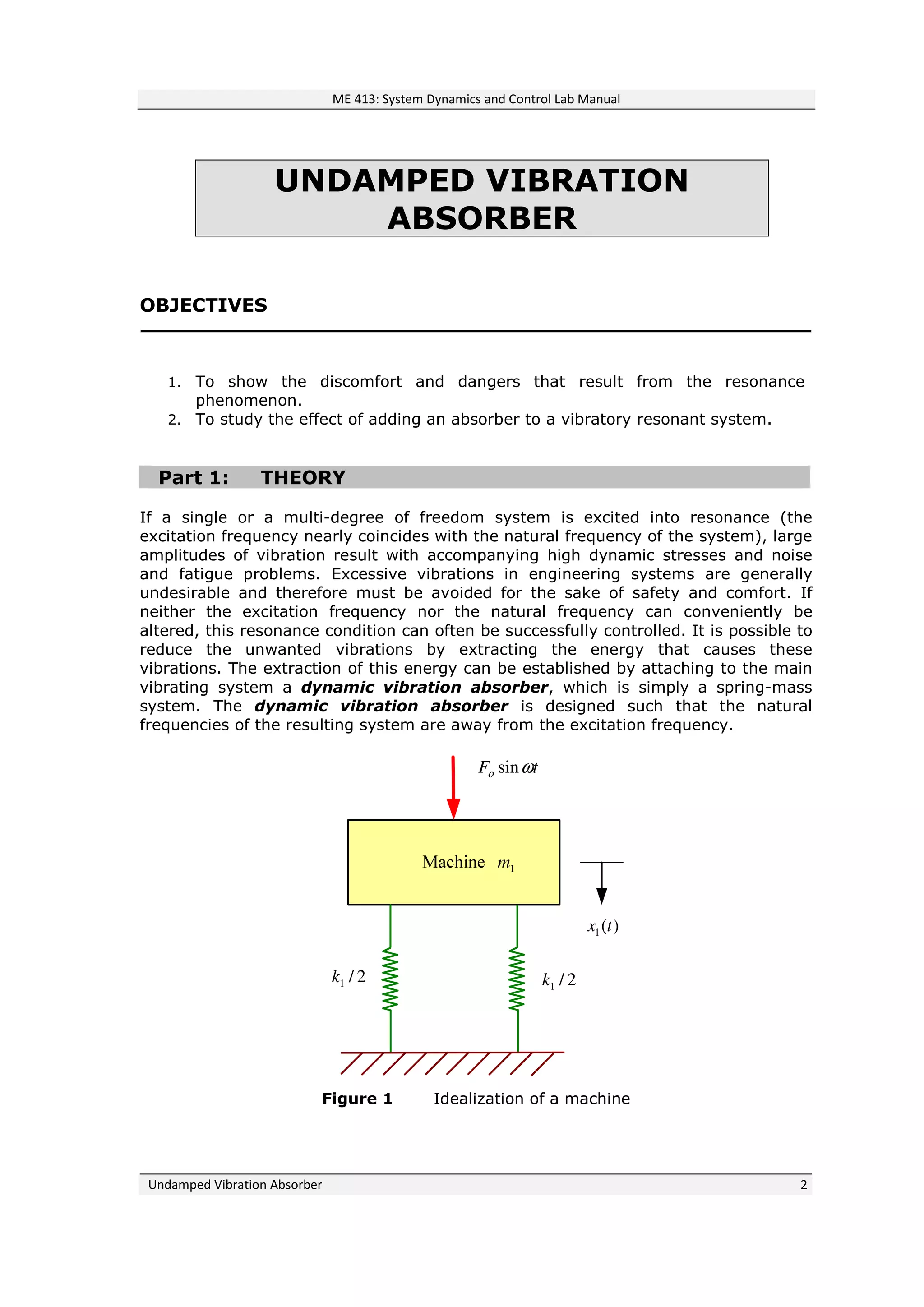
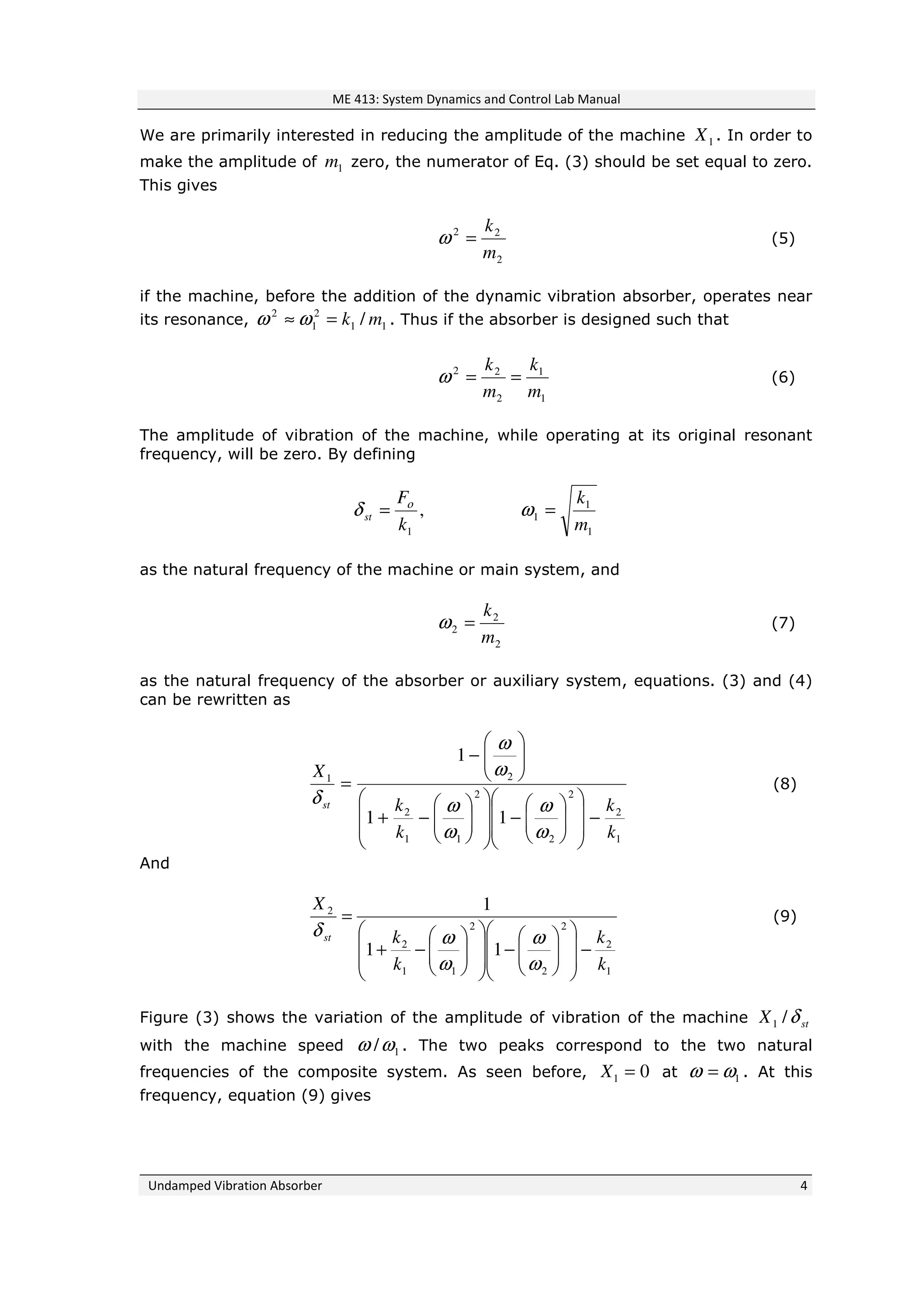
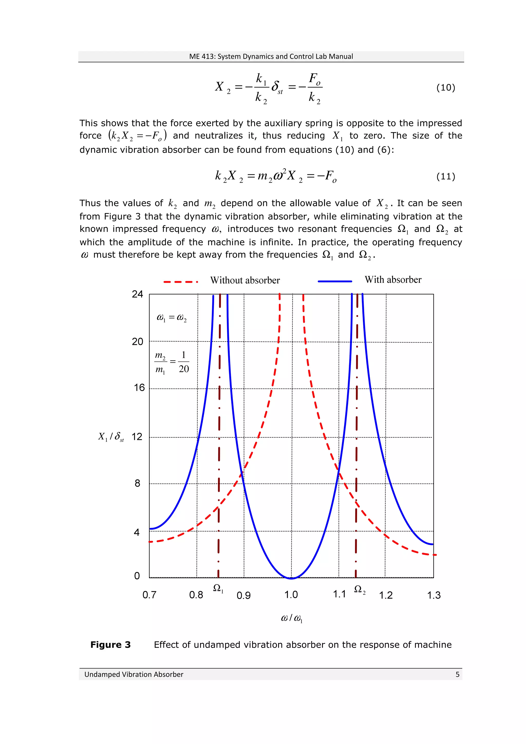
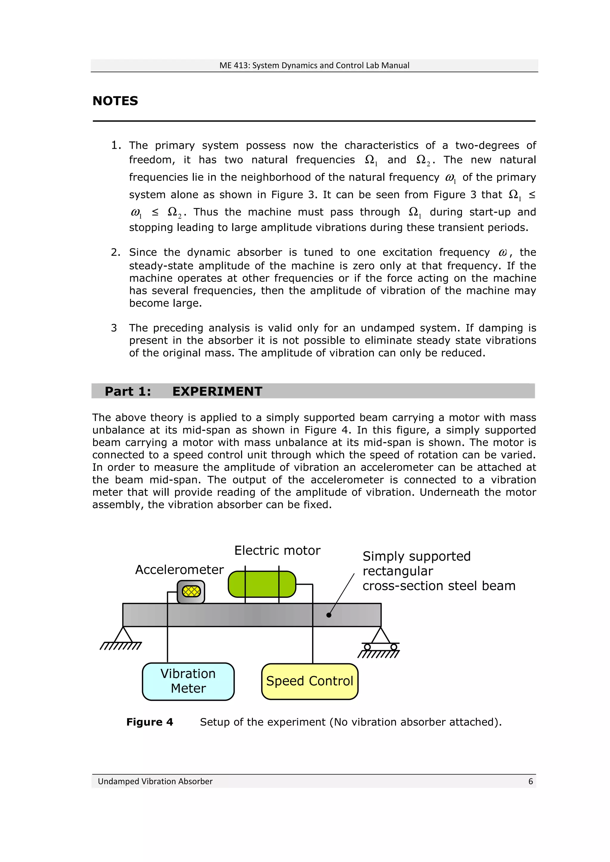
This document provides a theory and experimental procedure for demonstrating an undamped vibration absorber. The theory section explains how attaching an auxiliary mass-spring system to a vibrating object can reduce vibrations by extracting the energy that causes them. If the absorber's natural frequency matches the object's frequency, the object's amplitude can be reduced to zero. The experiment uses a beam with a motor to induce vibrations, and an absorber attached below to reduce the beam's amplitude at different motor speeds by adjusting the absorber's mass positions. The goal is to determine the absorber configuration that minimizes the beam's vibrations.
single degree of freedom systems forced vibrations KESHAV
SDOF, Forced vibration
includes following content
Forced vibrations of longitudinal and torsional systems,
Frequency Response to harmonic excitation,
excitation due to rotating and reciprocating unbalance,
base excitation, magnification factor,
Force and Motion transmissibility,
Quality Factor.
Half power bandwidth method,
Critical speed of shaft having single rotor of undamped systems.
ME010 801 Design of Transmission Elements
(Common with AU010 801)
Teaching scheme Credits: 4
2 hours lecture, 2 hour tutorial and 1 hour drawing per week
Objectives
To provide basic design skill with regard to various transmission elements like clutches, brakes, bearings and
gears.
Module I (20 Hrs)
Clutches - friction clutches- design considerations-multiple disc clutches-cone clutch- centrifugal clutch -
Brakes- Block brake- band brake- band and block brake-internal expanding shoe brake.
Module II (17 Hrs)
Design of bearings - Types - Selection of a bearing type - bearing life - Rolling contact bearings - static
and dynamic load capacity - axial and radial loads - selection of bearings - dynamic equivalent load -
lubrication and lubricants - viscosity - Journal bearings - hydrodynamic theory - design considerations -
heat balance - bearing characteristic number - hydrostatic bearings.
Module III (19 Hrs)
Gears- classification- Gear nomenclature - Tooth profiles - Materials of gears - design of spur, helical,
bevel gears and worm & worm wheel - Law of gearing - virtual or formative number of teeth- gear tooth
failures- Beam strength - Lewis equation- Buckingham’s equation for dynamic load- wear loadendurance strength of tooth- surface durability- heat dissipation - lubrication of gears - Merits and
demerits of each type of gears.
Module IV (16 Hrs)
Design of Internal Combustion Engine parts- Piston, Cylinder, Connecting rod, Flywheel
Design recommendations for Forgings- castings and welded products- rolled sections- turned parts,
screw machined products- Parts produced on milling machines. Design for manufacturing - preparation
of working drawings - working drawings for manufacture of parts with complete specifications including
manufacturing details.
Note: Any one of the following data book is permitted for reference in the final University examination:
1. Machine Design Data hand book by K. Lingaiah, Suma Publishers, Bangalore/ Tata Mc Graw Hill
2. PSG Design Data, DPV Printers, Coimbatore.
Text Books
1. C.S,Sarma, Kamlesh Purohit, Design of Machine Elements Prentice Hall of India Ltd NewDelhi
2. V.B.Bhandari, Design of Machine Elements McGraw Hill Book Company
3. M. F. Spotts, T. E. Shoup, Design of Machine Elements, Pearson Education.
Reference Books
1. J. E. Shigley, Mechanical Engineering Design, McGraw Hill Book Company.
2. Juvinall R.C & Marshek K.M., Fundamentals of Machine Component Design, John Wiley
3. Doughtie V.L., & Vallance A.V., Design of Machine Elements, McGraw Hill Book Company.
4. Siegel, Maleev & Hartman, Mechanical Design of Machines, International Book Company
This presentation gives the information about 'vibration measuring instruments' covering syllabus of Unit-5 of Theory of vibrations or mechanical vibrations for BE course under VTU, Belgaum. This presentation is prepared by Hareesha N G, Asst. Prof, Dept of Aerospace, DSCE, B'Lore-78.
This document is about power transmission system. It's aimed those interested in learning about mechanical engineering and students who are studying various programmes in engineering. This document only deals with power transmission through flat and v-belts.
Unit 4- balancing of rotating masses, Dynamics of machines of VTU Syllabus prepared by Hareesha N Gowda, Asst. Prof, Dayananda Sagar College of Engg, Blore. Please write to hareeshang@gmail.com for suggestions and criticisms.
Bending Stresses are important in the design of beams from strength point of view. The present source gives an idea on theory and problems in bending stresses.
Unit 5- balancing of reciprocating masses, Dynamics of machines of VTU Syllabus prepared by Hareesha N Gowda, Asst. Prof, Dayananda Sagar College of Engg, Blore. Please write to hareeshang@gmail.com for suggestions and criticisms.
The purpose of this project is to compare the Normal Stresses induced in the Knuckle-Joint due to application of Tensile Force of 12KN by manual calculations and using Ansys Workbench. Also, to find minimum and maximum stress and Deformation in the Joint. In this report, Stresses found analytically are compared with the stresses found by the Analysis Software.
DESIGN AND ANALYSIS OF CONNECTING ROD USING ALUMINIUM ALLOY 7068 T6, T6511 IAEME Publication
The connecting rod is the intermediate member between the piston and the Crankshaft. Its primary function is to transmit the push and pull from the piston pin to the crank pin, thus converting the reciprocating motion of the piston into rotary motion of the crank. This thesis describes designing
and Analysis of connecting rod. Currently existing connecting rod is manufactured by using Forged steel. In this drawing is drafted from the calculations.
Application of Numerical and Experimental Simulations for the Vibrating Syste...IJERD Editor
In this work,there may be some requirements of finding out the coupling loss factors of system component.It becomes difficult to exactly know the coupling loss factor by looking at the behavior of the system. For this purpose, the numerical solution developed in this work. Initially, one need to extract the displacement, velocity and energy profiles of the system which has got the components installed for which the coupling loss factor need to be determined. Then the numerical simulations can be run for different coupling loss factor of the vibrating system and the coupling loss factor can be found when the simulation results match with the experimental measurements. In this paper the experimentation is carried out i for the model a)Pre-design application of the work developed. b) Post design application of the work developed. The numerical results converge very well towards the experimental results as the coupling loss factor in simulation is varied towards the actual value. Similarly, for the second approach the experimental results converge towards the simulation results of 0.15 as the coupling loss factor of the damper that is installed on the system is varied towards 0.15.
ER Publication,
IJETR, IJMCTR,
Journals,
International Journals,
High Impact Journals,
Monthly Journal,
Good quality Journals,
Research,
Research Papers,
Research Article,
Free Journals, Open access Journals,
erpublication.org,
Engineering Journal,
Science Journals,
Engineering Research Publication
Best International Journals, High Impact Journals,
International Journal of Engineering & Technical Research
ISSN : 2321-0869 (O) 2454-4698 (P)
www.erpublication.org
In this article, we are interested in the improvement of the performances of Doubly Fed Induction Machine (DFIM) operating in motor mode by the use of the direct torque control (DTC). Firstly, we focused on the modeling of the DFIM and the study of the principle of functioning of the DTC control. Then, we implement this control on the Matlab/Simulink environment. Secondly, we present the simulation results of the proposed control. The analysis of these results shows clearly that the system based on the DFIM studied follows perfectly the set points, what allowed us to justify the efficiency of the elaborate control.
Research on the synchronous vibration of the non-integral mechanism under the...IJRES Journal
This article proposes and designs the internal structure of the electrical cabinet which can achieve
the 3-DOF (degrees-of-freedom) motion, and making it in the horizontal vibration environment with excitation
frequency of 12.5Hz.Obtaining vibrational properties of its internal structure through the Simulink simulation
results, which is to said that manipulator and low-voltage electrical appliances are not in the synchronous
conditions. But it is necessary to make it in a state of near synchronization to ensure the accuracy of the reliability
test of the variable load load with low-voltage electrical appliances. On this issue,to achieve the desired results
through the PID feedback control to further optimize.
Experimental study of the forces above and under the vibration insulators of ...eSAT Journals
Abstract This paper presents an established measuring system of the forces above and under the vibration insulators of the unit with a four-cylinder diesel engine and electric generator. Here are presented the components of the measurement system and the methodology created for measurements of bearings reactions above and under the elastic suspension elements of the unit, in a vertical direction, in which the data for the measured value is stored, processed and visualized in a MATLAB environment. The results that were obtained from the measurements of the forces above and under the four vibration insulators of the diesel generator are analyzed and graphically presented in this paper, as a function of the time at the transitional modes: starting, stopping, uploading and downloading with electrical load. The results that were obtained from measurements of the forces above and under the four vibration insulators of the diesel generator and per one working cycle of the diesel engine are presented and analyzed in this paper, as a function of the angle of rotation of the crankshaft at full load (maximum electrical load) and at idle running (without electrical load). With the thus created measurement system and methodology, scientific and applied researches can be conducted, in order to determine the quality of the vibration insulation of machine units with internal combustion engines. Keywords: Internal combustion engines, diesel generator, measuring, experimental study.
Experimental study of the forces above and under the vibration insulators of ...eSAT Publishing House
IJRET : International Journal of Research in Engineering and Technology is an international peer reviewed, online journal published by eSAT Publishing House for the enhancement of research in various disciplines of Engineering and Technology. The aim and scope of the journal is to provide an academic medium and an important reference for the advancement and dissemination of research results that support high-level learning, teaching and research in the fields of Engineering and Technology. We bring together Scientists, Academician, Field Engineers, Scholars and Students of related fields of Engineering and Technology
Sachpazis:Terzaghi Bearing Capacity Estimation in simple terms with Calculati...Dr.Costas Sachpazis
Terzaghi's soil bearing capacity theory, developed by Karl Terzaghi, is a fundamental principle in geotechnical engineering used to determine the bearing capacity of shallow foundations. This theory provides a method to calculate the ultimate bearing capacity of soil, which is the maximum load per unit area that the soil can support without undergoing shear failure. The Calculation HTML Code included.
Event Management System Vb Net Project Report.pdfKamal Acharya
In present era, the scopes of information technology growing with a very fast .We do not see any are untouched from this industry. The scope of information technology has become wider includes: Business and industry. Household Business, Communication, Education, Entertainment, Science, Medicine, Engineering, Distance Learning, Weather Forecasting. Carrier Searching and so on.
My project named “Event Management System” is software that store and maintained all events coordinated in college. It also helpful to print related reports. My project will help to record the events coordinated by faculties with their Name, Event subject, date & details in an efficient & effective ways.
In my system we have to make a system by which a user can record all events coordinated by a particular faculty. In our proposed system some more featured are added which differs it from the existing system such as security.
Vaccine management system project report documentation..pdfKamal Acharya
The Division of Vaccine and Immunization is facing increasing difficulty monitoring vaccines and other commodities distribution once they have been distributed from the national stores. With the introduction of new vaccines, more challenges have been anticipated with this additions posing serious threat to the already over strained vaccine supply chain system in Kenya.
CFD Simulation of By-pass Flow in a HRSG module by R&R Consult.pptxR&R Consult
CFD analysis is incredibly effective at solving mysteries and improving the performance of complex systems!
Here's a great example: At a large natural gas-fired power plant, where they use waste heat to generate steam and energy, they were puzzled that their boiler wasn't producing as much steam as expected.
R&R and Tetra Engineering Group Inc. were asked to solve the issue with reduced steam production.
An inspection had shown that a significant amount of hot flue gas was bypassing the boiler tubes, where the heat was supposed to be transferred.
R&R Consult conducted a CFD analysis, which revealed that 6.3% of the flue gas was bypassing the boiler tubes without transferring heat. The analysis also showed that the flue gas was instead being directed along the sides of the boiler and between the modules that were supposed to capture the heat. This was the cause of the reduced performance.
Based on our results, Tetra Engineering installed covering plates to reduce the bypass flow. This improved the boiler's performance and increased electricity production.
It is always satisfying when we can help solve complex challenges like this. Do your systems also need a check-up or optimization? Give us a call!
Work done in cooperation with James Malloy and David Moelling from Tetra Engineering.
More examples of our work https://www.r-r-consult.dk/en/cases-en/
Hybrid optimization of pumped hydro system and solar- Engr. Abdul-Azeez.pdffxintegritypublishin
Advancements in technology unveil a myriad of electrical and electronic breakthroughs geared towards efficiently harnessing limited resources to meet human energy demands. The optimization of hybrid solar PV panels and pumped hydro energy supply systems plays a pivotal role in utilizing natural resources effectively. This initiative not only benefits humanity but also fosters environmental sustainability. The study investigated the design optimization of these hybrid systems, focusing on understanding solar radiation patterns, identifying geographical influences on solar radiation, formulating a mathematical model for system optimization, and determining the optimal configuration of PV panels and pumped hydro storage. Through a comparative analysis approach and eight weeks of data collection, the study addressed key research questions related to solar radiation patterns and optimal system design. The findings highlighted regions with heightened solar radiation levels, showcasing substantial potential for power generation and emphasizing the system's efficiency. Optimizing system design significantly boosted power generation, promoted renewable energy utilization, and enhanced energy storage capacity. The study underscored the benefits of optimizing hybrid solar PV panels and pumped hydro energy supply systems for sustainable energy usage. Optimizing the design of solar PV panels and pumped hydro energy supply systems as examined across diverse climatic conditions in a developing country, not only enhances power generation but also improves the integration of renewable energy sources and boosts energy storage capacities, particularly beneficial for less economically prosperous regions. Additionally, the study provides valuable insights for advancing energy research in economically viable areas. Recommendations included conducting site-specific assessments, utilizing advanced modeling tools, implementing regular maintenance protocols, and enhancing communication among system components.
Overview of the fundamental roles in Hydropower generation and the components involved in wider Electrical Engineering.
This paper presents the design and construction of hydroelectric dams from the hydrologist’s survey of the valley before construction, all aspects and involved disciplines, fluid dynamics, structural engineering, generation and mains frequency regulation to the very transmission of power through the network in the United Kingdom.
Author: Robbie Edward Sayers
Collaborators and co editors: Charlie Sims and Connor Healey.
(C) 2024 Robbie E. Sayers
Student information management system project report ii.pdfKamal Acharya
Our project explains about the student management. This project mainly explains the various actions related to student details. This project shows some ease in adding, editing and deleting the student details. It also provides a less time consuming process for viewing, adding, editing and deleting the marks of the students.
Democratizing Fuzzing at Scale by Abhishek Aryaabh.arya
Presented at NUS: Fuzzing and Software Security Summer School 2024
This keynote talks about the democratization of fuzzing at scale, highlighting the collaboration between open source communities, academia, and industry to advance the field of fuzzing. It delves into the history of fuzzing, the development of scalable fuzzing platforms, and the empowerment of community-driven research. The talk will further discuss recent advancements leveraging AI/ML and offer insights into the future evolution of the fuzzing landscape.
Final project report on grocery store management system..pdfKamal Acharya
In today’s fast-changing business environment, it’s extremely important to be able to respond to client needs in the most effective and timely manner. If your customers wish to see your business online and have instant access to your products or services.
Online Grocery Store is an e-commerce website, which retails various grocery products. This project allows viewing various products available enables registered users to purchase desired products instantly using Paytm, UPI payment processor (Instant Pay) and also can place order by using Cash on Delivery (Pay Later) option. This project provides an easy access to Administrators and Managers to view orders placed using Pay Later and Instant Pay options.
In order to develop an e-commerce website, a number of Technologies must be studied and understood. These include multi-tiered architecture, server and client-side scripting techniques, implementation technologies, programming language (such as PHP, HTML, CSS, JavaScript) and MySQL relational databases. This is a project with the objective to develop a basic website where a consumer is provided with a shopping cart website and also to know about the technologies used to develop such a website.
This document will discuss each of the underlying technologies to create and implement an e- commerce website.
Welcome to WIPAC Monthly the magazine brought to you by the LinkedIn Group Water Industry Process Automation & Control.
In this month's edition, along with this month's industry news to celebrate the 13 years since the group was created we have articles including
A case study of the used of Advanced Process Control at the Wastewater Treatment works at Lleida in Spain
A look back on an article on smart wastewater networks in order to see how the industry has measured up in the interim around the adoption of Digital Transformation in the Water Industry.
Forklift Classes Overview by Intella PartsIntella Parts
Discover the different forklift classes and their specific applications. Learn how to choose the right forklift for your needs to ensure safety, efficiency, and compliance in your operations.
For more technical information, visit our website https://intellaparts.com
2. ME 413: System Dynamics & ControlME 413: System Dynamics & ControlME 413: System Dynamics & ControlME 413: System Dynamics & Control
Undamped ViUndamped ViUndamped ViUndamped Vibration Absorberbration Absorberbration Absorberbration Absorber
Name: __________________________________
ID #: __________________________________
Section #: __________________________________
Due Date: __________________________________
Instructor __________________________________
3. ME 413: System Dynamics and Control Lab Manual
Undamped Vibration Absorber 2
UNDAMPED VIBRATION
ABSORBER
OBJECTIVES
1. To show the discomfort and dangers that result from the resonance
phenomenon.
2. To study the effect of adding an absorber to a vibratory resonant system.
Part 1: THEORY
If a single or a multi-degree of freedom system is excited into resonance (the
excitation frequency nearly coincides with the natural frequency of the system), large
amplitudes of vibration result with accompanying high dynamic stresses and noise
and fatigue problems. Excessive vibrations in engineering systems are generally
undesirable and therefore must be avoided for the sake of safety and comfort. If
neither the excitation frequency nor the natural frequency can conveniently be
altered, this resonance condition can often be successfully controlled. It is possible to
reduce the unwanted vibrations by extracting the energy that causes these
vibrations. The extraction of this energy can be established by attaching to the main
vibrating system a dynamic vibration absorber, which is simply a spring-mass
system. The dynamic vibration absorber is designed such that the natural
frequencies of the resulting system are away from the excitation frequency.
1m
)(1 tx
2/1k2/1k
tF ωο sin
Figure 1 Idealization of a machine
4. ME 413: System Dynamics and Control Lab Manual
Undamped Vibration Absorber 3
When we attach an auxiliary mass 2m to a machine of mass 1m through a spring of
stiffness 2k , the resulting two degrees of freedom system will look as shown in
Figure 2. The equations of motion of the masses 1m and 2m are
( )
( )
1 1 1 1 2 1 2
2 2 2 2 1
sin
0
m x k x k x x F t
m x k x x
ο ω+ + − =
+ − =
(1)
By assuming a harmonic solution,
tXtx jj ωsin)( = , j=1, 2 (2)
We can obtain the steady-state amplitude of the masses 1m and 2m as we can
obtain
2
2
2
22
2
121
2
22
1
kmkmkk
Fmk
X
−−−+
−
=
))((
)(
ωω
ω ο
(3)
2
2
2
22
2
121
2
2
kmkmkk
Fk
X
−−−+
=
))(( ωω
ο
(4)
Machine 1m
)(1 tx
2/1k2/1k
tF ωο sin
)(2 tx
2m
2k
vibration absorber
Figure 2 Dynamic vibration absorber
5. ME 413: System Dynamics and Control Lab Manual
Undamped Vibration Absorber 4
We are primarily interested in reducing the amplitude of the machine 1X . In order to
make the amplitude of 1m zero, the numerator of Eq. (3) should be set equal to zero.
This gives
2
22
m
k
=ω (5)
if the machine, before the addition of the dynamic vibration absorber, operates near
its resonance, 11
2
1
2
/ mk=≈ ωω . Thus if the absorber is designed such that
1
1
2
22
m
k
m
k
==ω (6)
The amplitude of vibration of the machine, while operating at its original resonant
frequency, will be zero. By defining
,
1k
F
st
ο
δ =
1
1
1
m
k
=ω
as the natural frequency of the machine or main system, and
2
2
2
m
k
=ω (7)
as the natural frequency of the absorber or auxiliary system, equations. (3) and (4)
can be rewritten as
1
2
2
2
2
11
2
21
11
1
k
k
k
k
X
st
−
−
−+
−
=
ω
ω
ω
ω
ω
ω
δ
(8)
And
1
2
2
2
2
11
2
2
11
1
k
k
k
k
X
st
−
−
−+
=
ω
ω
ω
ωδ
(9)
Figure (3) shows the variation of the amplitude of vibration of the machine stX δ/1
with the machine speed 1/ωω . The two peaks correspond to the two natural
frequencies of the composite system. As seen before, 01 =X at 1ωω = . At this
frequency, equation (9) gives
6. ME 413: System Dynamics and Control Lab Manual
Undamped Vibration Absorber 5
1
2
2 2
st
Fk
X
k k
ο
δ= − = − (10)
This shows that the force exerted by the auxiliary spring is opposite to the impressed
force ( )οFXk −=22 and neutralizes it, thus reducing 1X to zero. The size of the
dynamic vibration absorber can be found from equations (10) and (6):
2
2 2 2 2k X m X Fοω= = − (11)
Thus the values of 2k and 2m depend on the allowable value of 2X . It can be seen
from Figure 3 that the dynamic vibration absorber, while eliminating vibration at the
known impressed frequency ,ω introduces two resonant frequencies 1Ω and 2Ω at
which the amplitude of the machine is infinite. In practice, the operating frequency
ω must therefore be kept away from the frequencies 1Ω and 2Ω .
2Ω1Ω
21 ωω =
20
1
1
2
=
m
m
stX δ/1
1/ωω
Figure 3 Effect of undamped vibration absorber on the response of machine
7. ME 413: System Dynamics and Control Lab Manual
Undamped Vibration Absorber 6
NOTES
1. The primary system possess now the characteristics of a two-degrees of
freedom, it has two natural frequencies 1Ω and 2Ω . The new natural
frequencies lie in the neighborhood of the natural frequency 1ω of the primary
system alone as shown in Figure 3. It can be seen from Figure 3 that 1Ω ≤
1ω ≤ 2Ω . Thus the machine must pass through 1Ω during start-up and
stopping leading to large amplitude vibrations during these transient periods.
2. Since the dynamic absorber is tuned to one excitation frequency ω , the
steady-state amplitude of the machine is zero only at that frequency. If the
machine operates at other frequencies or if the force acting on the machine
has several frequencies, then the amplitude of vibration of the machine may
become large.
3 The preceding analysis is valid only for an undamped system. If damping is
present in the absorber it is not possible to eliminate steady state vibrations
of the original mass. The amplitude of vibration can only be reduced.
Part 1: EXPERIMENT
The above theory is applied to a simply supported beam carrying a motor with mass
unbalance at its mid-span as shown in Figure 4. In this figure, a simply supported
beam carrying a motor with mass unbalance at its mid-span is shown. The motor is
connected to a speed control unit through which the speed of rotation can be varied.
In order to measure the amplitude of vibration an accelerometer can be attached at
the beam mid-span. The output of the accelerometer is connected to a vibration
meter that will provide reading of the amplitude of vibration. Underneath the motor
assembly, the vibration absorber can be fixed.
Figure 4 Setup of the experiment (No vibration absorber attached).
8. ME 413: System Dynamics and Control Lab Manual
Undamped Vibration Absorber 7
Apparatus
1. The absorber
Figure 5 shows the vibration absorber clamped below the motor. It comprises two
bodies of equal mass fixed equidistant from the midpoint of the horizontal cantilever.
The distance apart of the bodies varies until the system is ‘tuned’.
l
Figure 5 The vibration absorber clamped below the motor.
2. Speed Control Unit and Exciter Motor
Figure 6 shows the speed control unit that is used in this experiment. A d.c. motor is
used for all forced vibrations experiments powered by a control unit. This
combination comprises of a control box and d.c. motor, which provides high precision
speed control of the motor up to 3000 rev/min, irrespective of the normal load
fluctuations of the motor.
The front panel of the unit contains a speed control, a fully calibrated speed meter
incorporating an automatic range switching device (there being two ranges: 0 – 1500
and 1500 – 3000 rev/min), and a power socket for:
1. Mains inputs
2. d.c. motor
3. Auxiliary output (either to stroboscope or chart recorder), sometimes
marked drum supply.
9. ME 413: System Dynamics and Control Lab Manual
Undamped Vibration Absorber 8
Figure 6 Speed control unit front panel layout.
3. Vibration Meter Type 2511
The Vibration Meter Type 2511 shown in Figure 7 is a wide range instrument that is
used in conjunction with piezo-electric vibration pick-up to measure mechanical
vibration and shock in terms of acceleration, velocity and displacement. It is
completely portable and is built to a high standard of accuracy and stability making it
suitable for laboratory and field conditions. The instrument is fully calibrated in both
metric and British units and has a charge amplifier input that allows the use of long
cables between the pick-up and the meter without any reduction in sensitivity.
Figure 7 Front panel of the 2511 Type Vibration Meter.
10. ME 413: System Dynamics and Control Lab Manual
Undamped Vibration Absorber 9
Figure 8 Rear panel of the 2511 Type Vibration Meter.
4. Transducer (Accelerometer)
In general, the transducers employed in vibration analyses convert mechanical
energy into electrical energy; that is, they produce an electrical signal which is a
function of mechanical vibration. See Figure 5.
Figure 9 Accelerometers.
11. ME 413: System Dynamics and Control Lab Manual
Undamped Vibration Absorber 10
Procedure
For a given frequency, the masses of the vibration absorber are adjusted along their
cantilever leaf spring so that the energy of vibration transmits to the absorber and
the amplitude of the main (primary) system, i.e. the motor and beam, is reduced to
zero.
The aim is to determine the length l , the distance of the center of each of the
bodies from the midpoint of the cantilever so that the natural frequency of transverse
vibration of this sub-system corresponds to the running speed of the main (primary)
system, i.e. the motor and beam.
IMPORTANT
For your safety and the safety of the equipment
WHEN THE SYSTEM VIBRATES AT RESONANCE CONDITIONS
DO NOT LET IT VIBRATE FOR A LONG PERIOD OF TIME
1. No Absorber
1. Turn the upper right switch of the Vibration Meter Type 2511 on displacement,
velocity or acceleration depending on what you are intending to measure.
2. Turn the lower right switch of the Vibration Meter Type 2511 for the
appropriate range (Range I: metric units and Range II: British units). Notice
that you are reading the amplitude of the quantity to be measured as shown
in Table 1.
Table 1 Reading of the Vibration Meter Type 2511
Quantity Equation of Motion
Reading Vibration Meter Type
2511
Displacement ( ) sinx t X tω= Displacement Amplitude: X
Velocity ( ) cosx t X tω ω= Velocity Amplitude: X ω
Acceleration
2
( ) sinx t X tω ω= − Acceleration Amplitude:
2
X ω−
3. Vary the motor speed and read the vibration amplitudes from the Vibration
Meter Type 2511.
4. For each speed, record your reading (vibration amplitude) in Table 2.
12. ME 413: System Dynamics and Control Lab Manual
Undamped Vibration Absorber 11
5. Increase the speed gradually until you get the resonance phenomenon that
results in large amplitudes of excessive vibrations. From the tabulated data
plot the response curve and determine the resonant frequency of the system.
2. With Absorber
1. With the auxiliary system (vibration absorber) attached, vary the motor speed
and record the corresponding frequency and the resulting amplitude of
vibration.
2. Repeat the above (1 to 4) steps of the previous case.
3. With the aid of the experimentally defined resonant frequency, the dynamic
vibration absorber is to be designed such that the frequency of oscillations is
equal to
3
1 3
2 2
EI
f
ml
ω
π π
= = (12)
where f is natural frequency of the auxiliary system, m is the mass of each
of the two bodies, and EI is the flexural rigidity of the double cantilever
beam. The mass m is a given constant and l is to be found from the above
formula.
4. One can easily conclude, that any three parameters of equation (12) can be
fixed, in order to determine the fourth parameter. In this experiment we will
determine the position of the mass m , at which the absorber effect is
verified. Experimentally, one can vary the position of the mass m , and excite
the system at the required excitation frequency until no vibrations of the
primary system are observed, or the position of the mass l can be
determined from equation (12), adjusted accordingly and the absorbing
effect can be verified.
13. ME 413: System Dynamics and Control Lab Manual
Undamped Vibration Absorber 12
REQUIREMENTS
The report should include the following:
1. Organize your measurements of the vibration amplitudes versus the rotational
speed as shown in Table 2.
2. Plot on the same graph the velocity amplitude X ω versus the rotational
speed for the cases with and without the dynamic vibration absorber. (Use
MATLAB or Excel).
3. Plot on the same graph the displacement amplitude X versus the
rotational speed for the cases with and without the dynamic vibration
absorber. (Use MATLAB or Excel)
4. Indicate resonant frequencies and the frequency at which the primary system
(no absorber included) has zero vibration
5. Measure the length l for which the amplitude of vibration is zero when the
absorber is used. Compare this by solving Equation (12) for the length l .
Use 200 GPaE = and
31
12
I bh= .
6. Give a brief discussion of your findings.
7. Give conclusions on the effect of the vibration absorber.
14. ME 413: System Dynamics and Control Lab Manual
Undamped Vibration Absorber 13
Table 2 Readings
With no Absorber
N
(rpm)
Disp.
Ampl.
(mm)
Vel.
Ampl.
(mm/s)
Acc.
Ampl.
(mm/s2
)
With Absorber
N
(rpm)
Disp.
Ampl.
(mm)
Vel.
Ampl.
(mm/s)
Acc.
Ampl.
(mm/s2
)
15. ME 413: System Dynamics and Control Lab Manual
Undamped Vibration Absorber 14
References
[1] Experiments in Vibration Using The TM 16 Universal Vibration, TQ Ltd
[2] K. Ogata, System Dynamics, Fourth Edition, Pearson Prentice Hall, 2004.
[3] S. S. Rao, Mechanical vibrations, SI Edition, Pearson Prentice Hall, 2005.
[4] http://ta.twi.tudelft.nl/nw/users/vuik/information/tacoma_eng.html
[5] http://abel.math.harvard.edu/archive/21b_fall_03/tacoma/
[6] http://perso.wanadoo.fr/olivier.granier/meca/accueil.htm
[7] http://www.kettering.edu/~drussell/Demos/absorber/DynamicAbsorber.html
[8] http://www.mfg.mtu.edu/cyberman/machtool/machtool/vibration/absorb.html
[9] http://www.kettering.edu/~drussell/Demos/absorber/DynamicAbsorber.html
View publication statsView publication stats