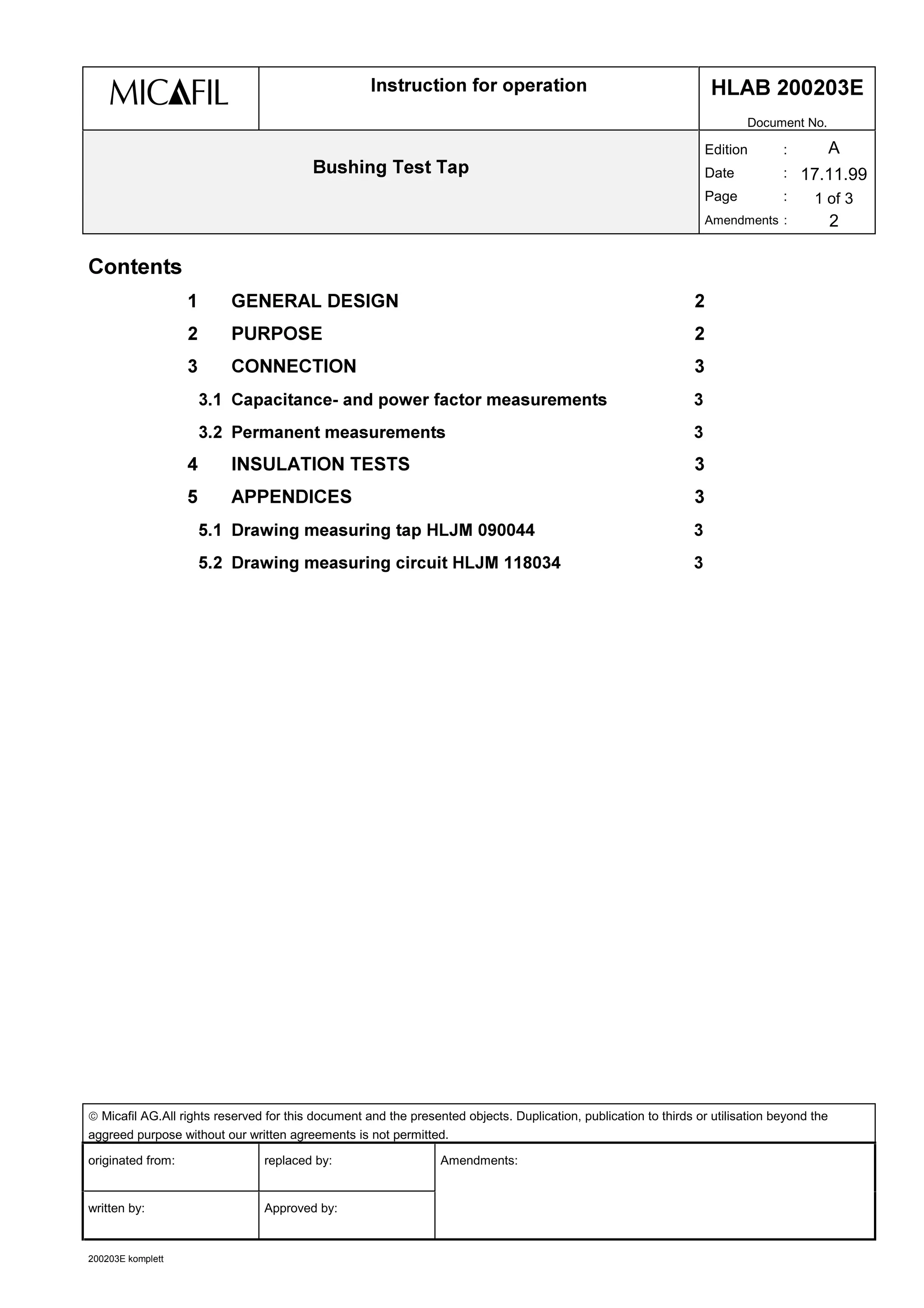
This document provides instructions for operating a bushing test tap. It discusses:
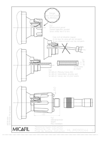
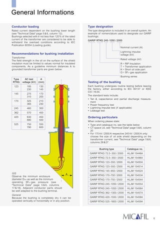
- The general design of the test tap, which allows access to a control layer insulated from the flange.
- The purposes of the test tap, which include measuring capacitance C1 and loss factor tan δ, as well as permanent voltage measurements or partial discharge monitoring at up to 1.5kV.
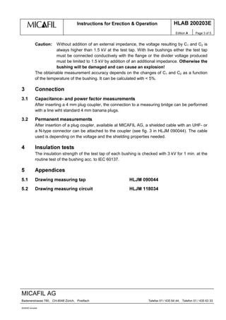
- Connection procedures for capacitance and power factor measurements or permanent measurements using a plug coupler and shielded cable.
- Insulation tests are done at 3kV for 1 minute during routine bushing testing according to IEC 60137.
![,QVWUXFWLRQV IRU (UHFWLRQ 2SHUDWLRQ +/$% (
Edition $ Page 2 of 5
MICAFIL AG
Badenerstrasse 780, CH-8048 Zürich, Postfach Telefax 01 / 435 64 44; Telefon 01 / 435 63 33
200203E komplett
*HQHUDO 'HVLJQ
The test tap is an accessory for capacitance graded bushings which makes it possible to
access a control layer insulated from the flange from the outside and thus to divide the total
capacitance of the bushing into 2 sub-capacitances C1 (high-voltage conductor-test layer)
and C2 (test layer-flange).
The test tap is designed, that a connection between the test layer and the flange is
automatically established, when the test tap is not in use. This connection can only be
opened by completely inserting a 4 mm plug coupler or by connecting a plu converter (see
figs. 2/3 in HLJM090044). For normal operation of the bushing the test tap should always be
closed with the supplied cover for protection.
3XUSRVH
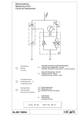
The normal purpose of the test tap is to measure the capacitance C1 and its loss factor tan δ.
The most common test circuit for this purpose is shown in the enclosed drawing
HLJM 118034.
The test tap can also be used to carry out a permanent voltage measurement or partial
discharge monitoring. The maximum permissible permanent voltage between the test layer
and the flange is 1.5 kV. Depending on the rated voltage and the capacitance of the bushing
it can be taken 5 .. 10 VA power from the test tap. There must be always connected an
impedance parallel to C2 to limit the voltage to ≤ 1.5 kV. This impedance is mostly a
capacitance Cz which must hav a minimum value
N9ED
ED
8
8 1 5,1
3/ 22
22
≤+⋅
+
=
The values of C1 and C2 can be taken from the test report for the particular bushing.
To get a specified voltage U it is necessary to use a capacitance Cz
min21 1
3
]
1
]
8
8
≥−
−
⋅
⋅=
To take reactive power from the test tap an ohmic resistor must be put in parallel to C2. the
possible power P which can be taken from the test tap is
( )
22
2
13/
ED5
8
3
]
1
+
⋅= with
1
2
1
D +=
]5
E
⋅
=
1
1
ω
However it is a requirement the U remains ≤ 1,5 kV. This can be checked with
N9ED
ED
8
8 1 5,1
3/ 22
22
≤+⋅
+
=](https://image.slidesharecdn.com/bushingtesttap-150811134327-lva1-app6892/85/Bushing-test-tap-2-320.jpg)