Downloaded 28 times


![REFERNECES
[1] http://en.wikipedia.org/wiki/Phase-locked_loop “Wikipedia the free
encyclopaedia”, accessed on January, 2007
[2] http://www.du.edu/~etuttle/electron/elect12.htm, “The phase locked loop”,
accessed on January, 2007
[3] http://perso.orange.fr/polyvalens/clemens/clemens.html, accessed on January,
2007
[4] http://www.w3.org “PI Controller” , accessed on January, 2007
[5] C. S. Chang, Zhemin Yu, “Distributed Mitigation of Voltage Sag by Optimal
Placement of Series Compensation Devices Based on Stochastic Assessment”,
IEEE transactions on Power Systems, Vol.19, No.2, May 2004, pg.788-795.
[6] Peradeniya University Annual Research Sessions (PURSE – 2006) held at
University of Peradeniya, Sri Lanka on November 30th 2006.
Topic of the Technical paper and presentation: Compensation techniques of the
Dynamic Voltage Restorer for single phase voltage sags.
[7] Second International Conference on Information and Automation 2006 (ICIA
2006)
held at Galadari Hotel, Colombo, Sri Lanka on 14-17th December 2006.
Topic of the Technical paper and presentation: Automated control technique for a
single phase Dynamic Voltage Restorer
Saturday, 24 March 2018 Marudhar Engineering College, Bikaner 18](https://image.slidesharecdn.com/keshav-180324032019/85/Dynamic-Voltage-Regulator-18-320.jpg)


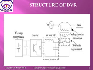
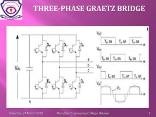
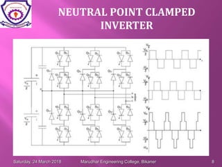
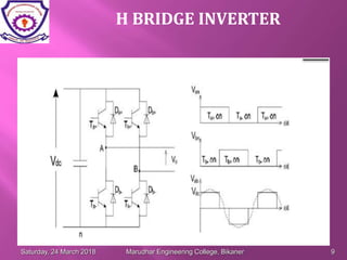
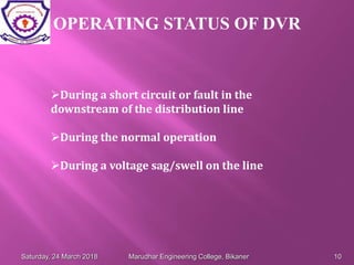
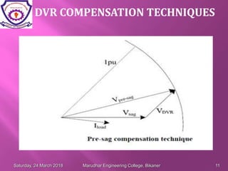
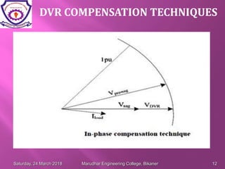
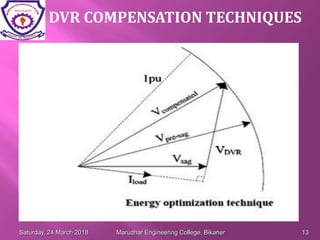
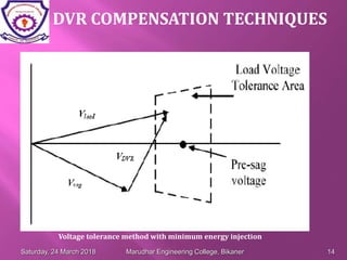
The document discusses dynamic voltage restorers (DVRs), which are power electronic devices that inject voltage into a distribution system to regulate load voltage during events like voltage sags or swells. It describes the structure and operating principles of DVRs, including various inverter topologies used. The document also covers DVR compensation techniques, voltage sag detection methods, and areas for further development like improving control strategies. The conclusion indicates that while three-phase DVR systems are common, less attention has been given to single-phase DVRs and their control, which the author aims to address.