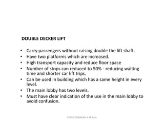
![History of Lifts
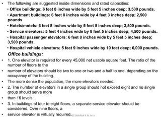
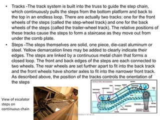
• Roman architect Vitruvius, reported that
Archimedes built his first elevator in 236
BC.[13] Elevators were mentioned as cabs on
a hemp rope and powered by hand or by
animals.
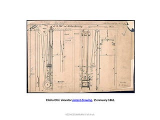
• In 1852, Elisha Otis introduced the safety elevator, which
prevented the fall of the cab if the cable broke. The design
of the Otis safety elevator is somewhat similar to one type
still used today.
• On March 23, 1857 the first Otis passenger elevator was
installed at 488 Broadway in New York City
• The Equitable Life Building completed in 1870 in New York
City was the first office building to have passenger
elevators.[20]
KEDHEESWARAN K M.Arch](https://image.slidesharecdn.com/lifandexcalator-181110154250/85/building-services-Lift-s-and-escalators-3-320.jpg)
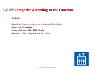
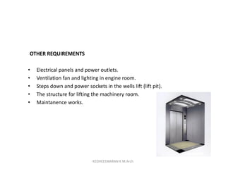

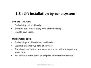


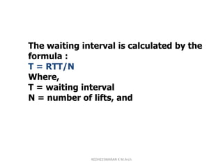


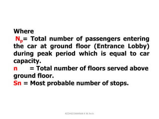
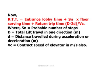
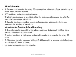
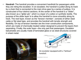
![Calculation of R.T.T.
The most probable number of floors on
which lift may have to be stopped is given
by statistical formula:
Sn = n [ 1-(n-1)/n)Np]
KEDHEESWARAN K M.Arch](https://image.slidesharecdn.com/lifandexcalator-181110154250/85/building-services-Lift-s-and-escalators-65-320.jpg)


1. The document discusses the history and development of elevators and escalators. It traces elevators back to 236 BC and discusses improvements like Elisha Otis' safety elevator in 1852. 2. It then covers various types of lifts according to function, including trade lifts, hospital lifts, high residential lifts, and others. It discusses characteristics, components, selection factors, and installation considerations for lifts. 3. The document also examines lift design considerations like population, handling capacity, interval, categories according to function, and installation by zone systems for tall buildings.