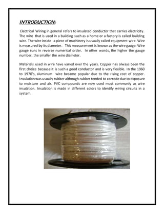
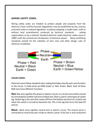
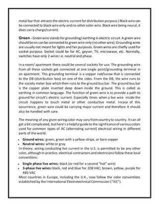
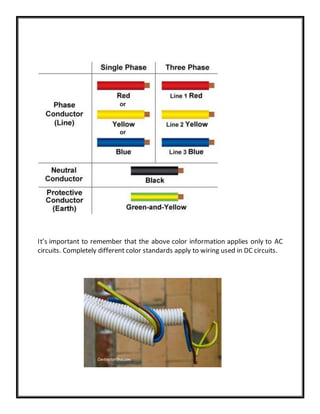
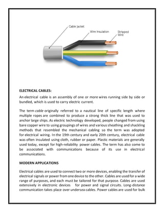
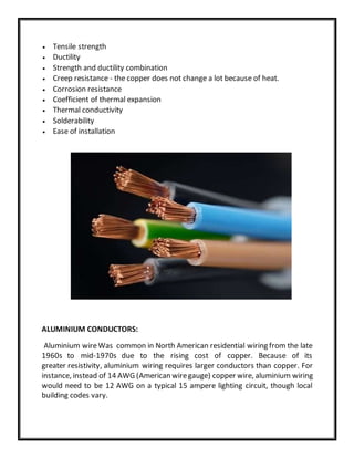
This document provides an overview of electrical wiring, including key terms, materials, safety codes, color codes, wiring methods, and cable types. It discusses how wire is measured and materials that have been used over time, such as copper and aluminum. Wiring safety codes are intended to protect people from electrical hazards. Common color codes for electrical wires include red for phase, black for neutral, and green for grounding. Wiring can be installed using either a joint box system or loop-in system. Different cable types are used for various applications such as building wiring, long-distance communication, and bulk power transmission.
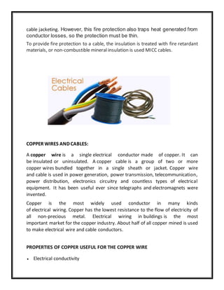
![JOB 1
AIM: To make a lamp work on a single way switch connection.
REQUIREMENTS:Onewayswitch,connecting wires,bulb[lamp],two phasesupply.
PROCEDURE:
1. Take a connecting wire/ cable.
2. Remove insulation from both ends of wire.
3. Connect one end to the one way switch ( lower end )
4. Now connect one end of wire to copper end of the switch and other end of the
wire to the one terminal of bulb.
5. Connect other terminal of bulb to a wire.
6. Insert two open ends in two phase supply.
PRECAUTIONS:
1. Join the ends very carefully.
2. Donot touch any joints and equipment when supply is switched on.
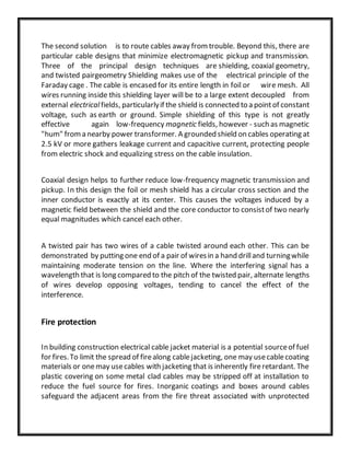
JOB 2](https://image.slidesharecdn.com/electricalwiring-190130102842/85/Electrical-wiring-16-320.jpg)
![AIM: To make connections of an extension board.
REQUIREMENTS: Two switches, Two sockets, a wooden box, mica sheet, screws,
one core wire, two core wire.[3m]
PROCEDURE:
1. Join the switches and sockets on mica sheet by screws.
2. Make the connections of wire inside the mica sheet.
3. Connect two core wire to phase and neutral .
4. Now attach mica sheet on the wooden box with the help of screws.
5. Check for the connections by inserting test pen into the socket and
simuntaneously test pen into extension board.
PRECAUTIONS:
1. Joints made must be tight.
2. Do not touch any equipment or joint while testing extension board.
JOB 4](https://image.slidesharecdn.com/electricalwiring-190130102842/85/Electrical-wiring-18-320.jpg)