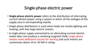
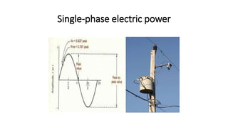
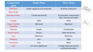
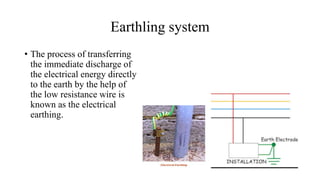
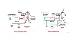
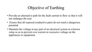
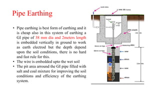
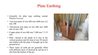
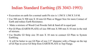
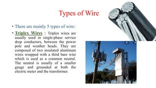
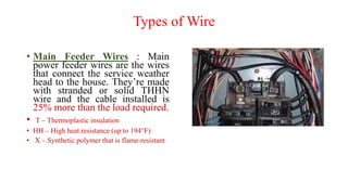
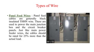
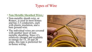
Electrical systems & Illumination
Design in Buildings
Basics of Electricity
• Electrical Charge: Electric charge is the physical property of matter that
causes it to experience a force when placed in an electromagnetic field.
There are two types of electric charges; positive and negative (commonly
carried by protons and electrons respectively).
• voltage :Voltage is defined as the amount of potential energy between two
points on a circuit. One point has more charge than another. This
difference in charge between the two points is called voltage. It is
measured in volts.
• Electric current: It is a flow of electric charge. In electric circuits this charge
is often carried by moving electrons in a wire. It can also be carried by ions
in an electrolyte. It is measured in Volts
Basics of Electricity
• Electrical resistance : The electrical resistance of an object is a
measure of its opposition to the flow of electric current.
• The SI unit of electrical resistance is the ohm (Ω)
Single-phase electric power
• Single-phase electric power refers to the distribution of alternating
current electric power using a system in which all the voltages of the
supply vary in corresponding exactly.
• Single-phase distribution is used when loads are mostly lighting and
heating, with few large electric motors.
• A single-phase supply connected to an alternating current electric
motor does not produce a revolving magnetic field; single-phase
motors need additional circuits for starting and such motors are
uncommon above 10 or 20 kW in rating.
Single-phase electric power
• The cycle repeats itself 60 times every second, which is where we get
the term 60-cycle or 60-hertz alternating current.
• Single-phase current requires the use of one transformer
Three-phase System
• A three-phase AC system consists of three-phase
• generators, transmission lines, and loads.
• The three-phase system has four wire, i.e., the three current carrying
conductors and the one neutral.
• Three-phase current requires two or three transformers.
Three-phase System
Comparison
point
Single Phase Three Phase
Definition Power supply by one conductor by three conductors
Wave Shape
Number of wire. 2 (load and neutral) 4 (generators, transmission
lines, Neutral and loads)
Voltage 230V 415V
Power Transfer
Capability
Minimum Maximum
Network Simple Complicated
Power Failure Occurs Does not Occurs
Loss Maximum Minimum
Efficiency Less High
Economical Less More
Uses For home appliances. In large industries and for
running heavy loads.
Earthling system
• The process of transferring
the immediate discharge of
the electrical energy directly
to the earth by the help of
the low resistance wire is
known as the electrical
earthing.
Objective of Earthing
• Provide an alternative path for the fault current to flow so that it will
not endanger the user
• Ensure that all exposed conductive parts do not reach a dangerous
potential
• Maintain the voltage at any part of an electrical system at a known
value so as to prevent over current or excessive voltage on the
appliances or equipment.
Importance of Earthing
• To save human life from danger of electrical shock or death by blowing a fuse i.e.
To provide an alternative path for the fault current to flow so that it will not
endanger the user
• To protect buildings, machinery & appliances under fault conditions ie. To ensure
that all exposed conductive parts do not reach a dangerous potential.
• To provide safe path to dissipate lightning and short circuit currents.
• To provide stable platform for operation of sensitive electronic equipments i.e. To
maintain the voltage at any part of an electrical system at a known value so as to
prevent over current or excessive voltage on the appliances or equipment.
• To provide protection against static electricity from friction
Earthing for lighting
Types of Electrical Earthing
A. Neutral Earthing
B. Equipment Earthing.
Neutral Earthing:
• The neutral earthing is also
called the system earthing.
• The neutral earthing is provided
in the generator, transformer,
motor etc.
Equipment Earthing.
• Such type of earthing is provided to the
electrical equipment.
• The non-current carrying part of the
equipment like their metallic frame is
connected to the earth by the help of the
conducting wire.
Construction of earthing as Per IS
• Two types of Earthing
1. Pipe Earthing
2. Plate earthing
Pipe Earthing
• Pipe earthing is best form of earthing and it
is cheap also in this system of earthing a
GI pipe of 38 mm dia and 2meters length
is embedded vertically in ground to work
as earth electrod but the depth depend
upon the soil conditions, there is no hard
and fast rule for this.
• The wire is embedded upto the wet soil
• The pit area arround the GI pipe filled with
salt and coal mixture for improving the soil
conditions and efficiency of the earthing
system.
Pipe Earthing
• In summmer season to have an effective earthing three or four bucket
of water is put through the funnel for better continuity of earthing.
Plate Earthing
• Generally for plate type earthing normal
Practice is to use
• Cast iron plate of size 600 mm x600 mm x12
mm. OR
• Galvanized iron plate of size 600 mm x600
mm x6 mm. OR
• Copper plate of size 600 mm * 600 mm * 3.15
mm
• Plate burred at the depth of 8 feet in the
vertical position and GI strip of size 50 mmx6
mm bolted with the plate is brought up to the
ground level.
• These types of earth pit are generally filled
with alternate layer of charcoal & salt up to 4
feet from the bottom of the pit.
Indian Standard Earthing (IS 3043-1993)
• Excavation on earth for a normal earth Pit size is 1.5M X 1.5M X 3.0 M.
• Use 500 mm X 500 mm X 10 mm GI Plate or Bigger Size for more Contact of
Earth and reduce Earth Resistance.
• Make a mixture of Wood Coal Powder Salt & Sand all in equal part
• Put GI Plate (EARTH PLATE) of size 500 mm X 500 mm X 10 mm in the mid
of mixture.
• Use Double GI Strip size 30 mm X 10 mm to connect GI Plate to System
Earthling.
• It will be better to use GI Pipe of size 2.5″ diameter with a Flange on the top
of GI Pipe to cover GI Strip from EARTH PLATE to Top Flange.
Indian Standard Earthing
• Maintain less than one Ohm resistance from EARTH PIT conductor to
a distance of 15 Meters around the EARTH PIT with another
conductor dip on the Earth at least 500 mm deep.
• Check Voltage between Earth Pit conductors to Neutral of Mains
Supply 220V AC 50 Hz it should be less than 2.0 Volts.
Electrical wires
• Points to be considered before choosing a wire.
1. Life of installation
2. Future extension or alterations
3. Construction of building
4. Fire hazards or other special conditions
5. Corrosive fumes
Electrical wires
6. Dampness
7. Type of wire and material used
8. Nature of load (lighting of power)
9. Safety of the system
10. Cost of wiring system
Factors affecting choise of wire
• Durability :Type of wiring selected should conform to standard
specifications, so that it is durable i.e. without being affected by the
weather conditions, fumes etc.
• Safety :The wiring must provide safety against leakage, shock
and fire hazards for the operating personnel.
• Appearance :Electrical wiring should give an aesthetic appeal
to the interiors.
• Cost:It should not be prohibitively expensive.
Factors affecting choise of wire
• Accessibility : The switches and plug points provided should be
easily accessible. There must be provision for further extension of
the wiring system, if necessary.
• Maintenance Cost : The maintenance cost should be a minimum.
• Mechanical safety : The wiring must be protected against
any mechanical damage.
Types of Wire
• There are mainly 5 types of wire:
• Triplex Wires : Triplex wires are
usually used in single-phase service
drop conductors, between the power
pole and weather heads. They are
composed of two insulated aluminum
wires wrapped with a third bare wire
which is used as a common neutral.
The neutral is usually of a smaller
gauge and grounded at both the
electric meter and the transformer.
Types of Wire
• Main Feeder Wires : Main
power feeder wires are the wires
that connect the service weather
head to the house. They’re made
with stranded or solid THHN
wire and the cable installed is
25% more than the load required.
• T – Thermoplastic insulation
• HH – High heat resistance (up to 194°F)
• X – Synthetic polymer that is flame-resistant
Types of Wire
• Panel Feed Wires : Panel feed
cables are generally black
insulated THHN wire. These are
used to power the main junction
box and the circuit breaker
panels. Just like main power
feeder wires, the cables should
be rated for 25% more than the
actual load.
Types of Wire
• Non-Metallic Sheathed Wires :
• Non-metallic sheath wire, or
Romex, is used in most homes
and has 2-3 conductors, each
with plastic insulation, and a
bare ground wire.
• The individual wires are covered
with another layer of non-
metallic sheathing. Since it’s
relatively cheaper and available
in ratings for 15, 20 and 20
amps, this type is preferred for
in-house wiring.
Types of Wire
• These are the following types of wiring are:-
1. Cleat wiring
2. Wood casting wiring
3. CTS wiring or TRS wiring or Batten wiring
4. Conduit wiring
5. Metal sheathed wiring or lead sheathed wiring
Types of wires, three phase system earthing

Types of wires, three phase system earthing

  • 1.
    Electrical systems &Illumination Design in Buildings
  • 2.
    Basics of Electricity •Electrical Charge: Electric charge is the physical property of matter that causes it to experience a force when placed in an electromagnetic field. There are two types of electric charges; positive and negative (commonly carried by protons and electrons respectively). • voltage :Voltage is defined as the amount of potential energy between two points on a circuit. One point has more charge than another. This difference in charge between the two points is called voltage. It is measured in volts. • Electric current: It is a flow of electric charge. In electric circuits this charge is often carried by moving electrons in a wire. It can also be carried by ions in an electrolyte. It is measured in Volts
  • 3.
    Basics of Electricity •Electrical resistance : The electrical resistance of an object is a measure of its opposition to the flow of electric current. • The SI unit of electrical resistance is the ohm (Ω)
  • 4.
    Single-phase electric power •Single-phase electric power refers to the distribution of alternating current electric power using a system in which all the voltages of the supply vary in corresponding exactly. • Single-phase distribution is used when loads are mostly lighting and heating, with few large electric motors. • A single-phase supply connected to an alternating current electric motor does not produce a revolving magnetic field; single-phase motors need additional circuits for starting and such motors are uncommon above 10 or 20 kW in rating.
  • 5.
  • 6.
    Single-phase electric power •The cycle repeats itself 60 times every second, which is where we get the term 60-cycle or 60-hertz alternating current. • Single-phase current requires the use of one transformer
  • 7.
    Three-phase System • Athree-phase AC system consists of three-phase • generators, transmission lines, and loads. • The three-phase system has four wire, i.e., the three current carrying conductors and the one neutral. • Three-phase current requires two or three transformers.
  • 8.
  • 9.
    Comparison point Single Phase ThreePhase Definition Power supply by one conductor by three conductors Wave Shape Number of wire. 2 (load and neutral) 4 (generators, transmission lines, Neutral and loads) Voltage 230V 415V Power Transfer Capability Minimum Maximum Network Simple Complicated Power Failure Occurs Does not Occurs Loss Maximum Minimum Efficiency Less High Economical Less More Uses For home appliances. In large industries and for running heavy loads.
  • 10.
    Earthling system • Theprocess of transferring the immediate discharge of the electrical energy directly to the earth by the help of the low resistance wire is known as the electrical earthing.
  • 12.
    Objective of Earthing •Provide an alternative path for the fault current to flow so that it will not endanger the user • Ensure that all exposed conductive parts do not reach a dangerous potential • Maintain the voltage at any part of an electrical system at a known value so as to prevent over current or excessive voltage on the appliances or equipment.
  • 13.
    Importance of Earthing •To save human life from danger of electrical shock or death by blowing a fuse i.e. To provide an alternative path for the fault current to flow so that it will not endanger the user • To protect buildings, machinery & appliances under fault conditions ie. To ensure that all exposed conductive parts do not reach a dangerous potential. • To provide safe path to dissipate lightning and short circuit currents. • To provide stable platform for operation of sensitive electronic equipments i.e. To maintain the voltage at any part of an electrical system at a known value so as to prevent over current or excessive voltage on the appliances or equipment. • To provide protection against static electricity from friction
  • 14.
  • 15.
    Types of ElectricalEarthing A. Neutral Earthing B. Equipment Earthing. Neutral Earthing: • The neutral earthing is also called the system earthing. • The neutral earthing is provided in the generator, transformer, motor etc.
  • 16.
    Equipment Earthing. • Suchtype of earthing is provided to the electrical equipment. • The non-current carrying part of the equipment like their metallic frame is connected to the earth by the help of the conducting wire.
  • 17.
    Construction of earthingas Per IS • Two types of Earthing 1. Pipe Earthing 2. Plate earthing
  • 18.
    Pipe Earthing • Pipeearthing is best form of earthing and it is cheap also in this system of earthing a GI pipe of 38 mm dia and 2meters length is embedded vertically in ground to work as earth electrod but the depth depend upon the soil conditions, there is no hard and fast rule for this. • The wire is embedded upto the wet soil • The pit area arround the GI pipe filled with salt and coal mixture for improving the soil conditions and efficiency of the earthing system.
  • 19.
    Pipe Earthing • Insummmer season to have an effective earthing three or four bucket of water is put through the funnel for better continuity of earthing.
  • 20.
    Plate Earthing • Generallyfor plate type earthing normal Practice is to use • Cast iron plate of size 600 mm x600 mm x12 mm. OR • Galvanized iron plate of size 600 mm x600 mm x6 mm. OR • Copper plate of size 600 mm * 600 mm * 3.15 mm • Plate burred at the depth of 8 feet in the vertical position and GI strip of size 50 mmx6 mm bolted with the plate is brought up to the ground level. • These types of earth pit are generally filled with alternate layer of charcoal & salt up to 4 feet from the bottom of the pit.
  • 21.
    Indian Standard Earthing(IS 3043-1993) • Excavation on earth for a normal earth Pit size is 1.5M X 1.5M X 3.0 M. • Use 500 mm X 500 mm X 10 mm GI Plate or Bigger Size for more Contact of Earth and reduce Earth Resistance. • Make a mixture of Wood Coal Powder Salt & Sand all in equal part • Put GI Plate (EARTH PLATE) of size 500 mm X 500 mm X 10 mm in the mid of mixture. • Use Double GI Strip size 30 mm X 10 mm to connect GI Plate to System Earthling. • It will be better to use GI Pipe of size 2.5″ diameter with a Flange on the top of GI Pipe to cover GI Strip from EARTH PLATE to Top Flange.
  • 22.
    Indian Standard Earthing •Maintain less than one Ohm resistance from EARTH PIT conductor to a distance of 15 Meters around the EARTH PIT with another conductor dip on the Earth at least 500 mm deep. • Check Voltage between Earth Pit conductors to Neutral of Mains Supply 220V AC 50 Hz it should be less than 2.0 Volts.
  • 23.
    Electrical wires • Pointsto be considered before choosing a wire. 1. Life of installation 2. Future extension or alterations 3. Construction of building 4. Fire hazards or other special conditions 5. Corrosive fumes
  • 24.
    Electrical wires 6. Dampness 7.Type of wire and material used 8. Nature of load (lighting of power) 9. Safety of the system 10. Cost of wiring system
  • 25.
    Factors affecting choiseof wire • Durability :Type of wiring selected should conform to standard specifications, so that it is durable i.e. without being affected by the weather conditions, fumes etc. • Safety :The wiring must provide safety against leakage, shock and fire hazards for the operating personnel. • Appearance :Electrical wiring should give an aesthetic appeal to the interiors. • Cost:It should not be prohibitively expensive.
  • 26.
    Factors affecting choiseof wire • Accessibility : The switches and plug points provided should be easily accessible. There must be provision for further extension of the wiring system, if necessary. • Maintenance Cost : The maintenance cost should be a minimum. • Mechanical safety : The wiring must be protected against any mechanical damage.
  • 27.
    Types of Wire •There are mainly 5 types of wire: • Triplex Wires : Triplex wires are usually used in single-phase service drop conductors, between the power pole and weather heads. They are composed of two insulated aluminum wires wrapped with a third bare wire which is used as a common neutral. The neutral is usually of a smaller gauge and grounded at both the electric meter and the transformer.
  • 28.
    Types of Wire •Main Feeder Wires : Main power feeder wires are the wires that connect the service weather head to the house. They’re made with stranded or solid THHN wire and the cable installed is 25% more than the load required. • T – Thermoplastic insulation • HH – High heat resistance (up to 194°F) • X – Synthetic polymer that is flame-resistant
  • 29.
    Types of Wire •Panel Feed Wires : Panel feed cables are generally black insulated THHN wire. These are used to power the main junction box and the circuit breaker panels. Just like main power feeder wires, the cables should be rated for 25% more than the actual load.
  • 30.
    Types of Wire •Non-Metallic Sheathed Wires : • Non-metallic sheath wire, or Romex, is used in most homes and has 2-3 conductors, each with plastic insulation, and a bare ground wire. • The individual wires are covered with another layer of non- metallic sheathing. Since it’s relatively cheaper and available in ratings for 15, 20 and 20 amps, this type is preferred for in-house wiring.
  • 31.
    Types of Wire •These are the following types of wiring are:- 1. Cleat wiring 2. Wood casting wiring 3. CTS wiring or TRS wiring or Batten wiring 4. Conduit wiring 5. Metal sheathed wiring or lead sheathed wiring