The document discusses electrical services including power generation, transmission, and distribution. It provides information on:
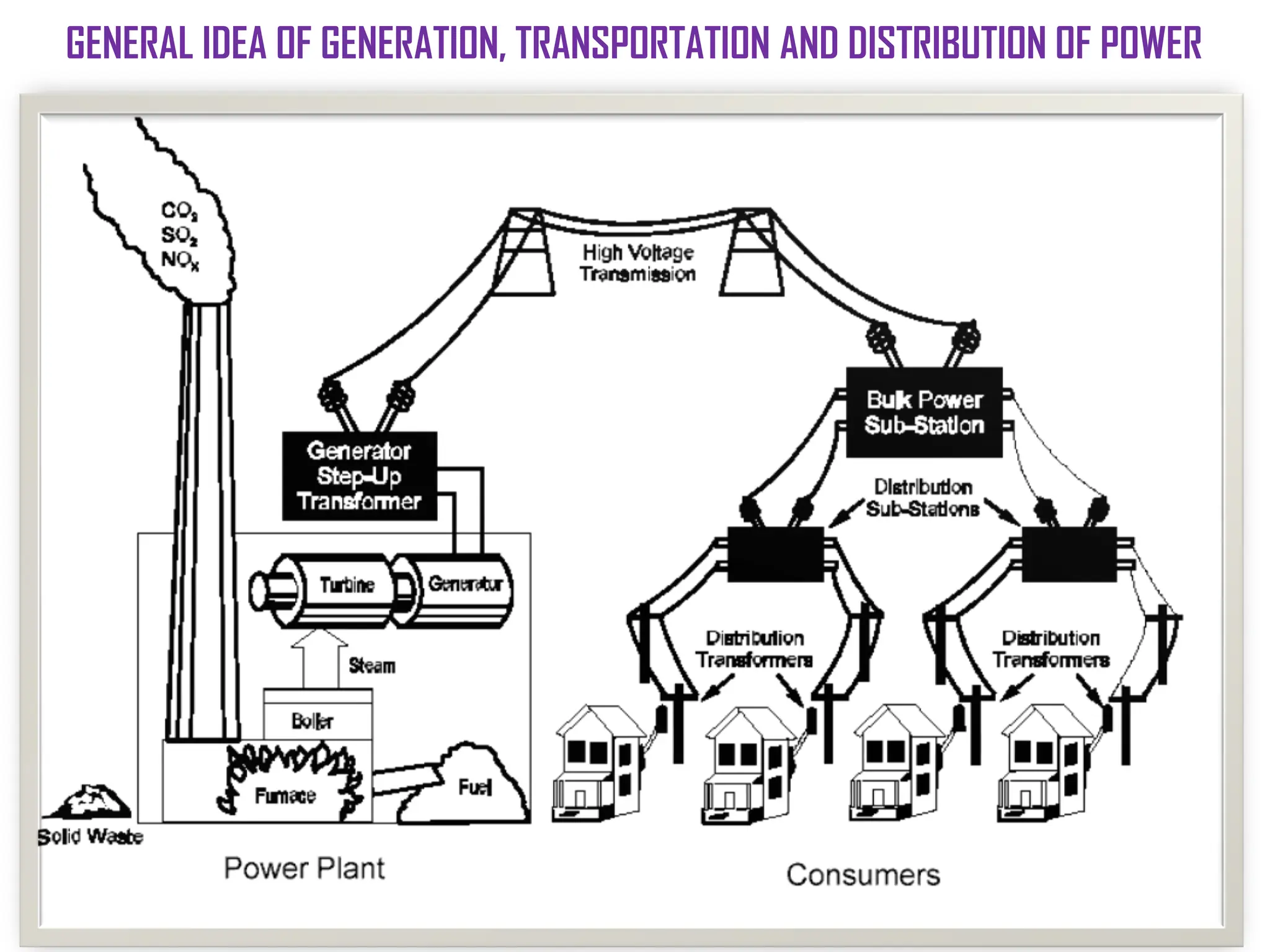
- How electricity is generated at power plants and increased in voltage for transmission through high voltage lines.
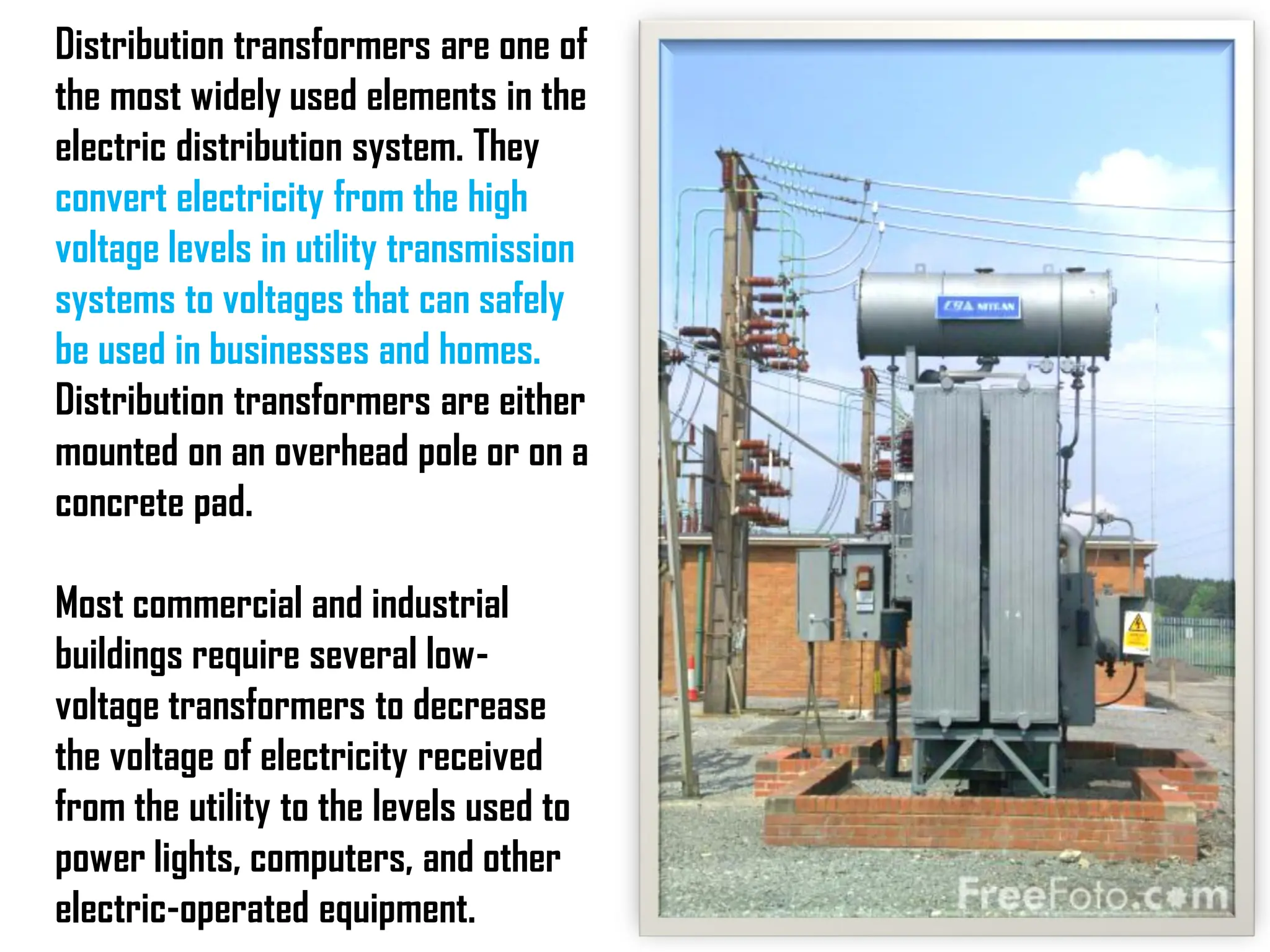
- How transmission substations reduce the voltage for further distribution and distribution substations further reduce the voltage for commercial and residential use.
- The components that link generators to end users including transformers, transmission lines, distribution lines, and substations.
![Modern power grids are extremely complex and
widespread. Surges in power lines can cause massive network
failures and permanent damage to multimillion-dollar equipment
in power generation plants.
After electricity is produced at power plants it has to get
to the customers that use the electricity. As generators spin,
they produce electricity with a voltage of about 25,000 volts [a
volt is a measurement of electromotive force in electricity, the
electric force that pushes electrons around a circuit].
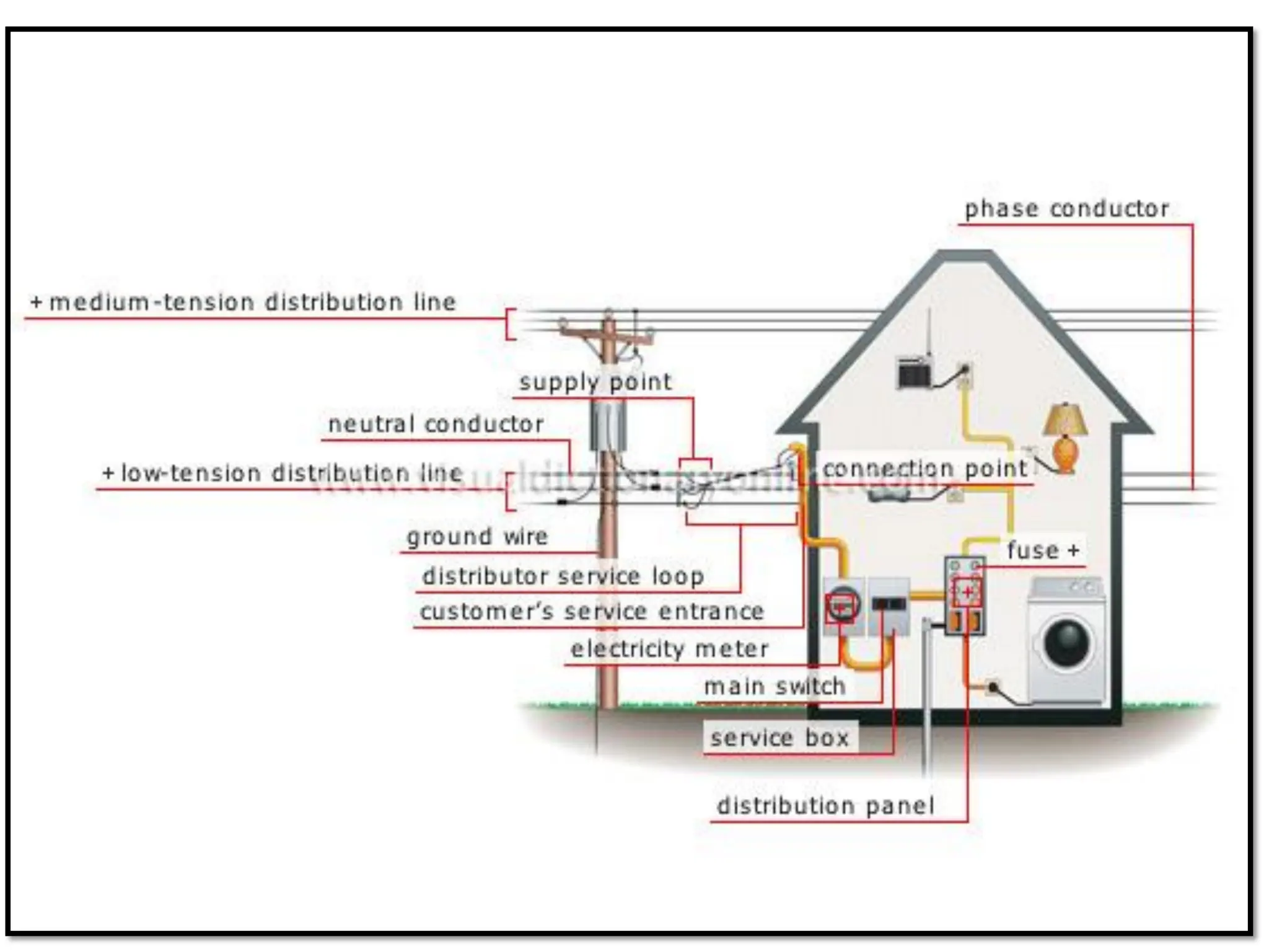
The transmission and distribution system delivers
electricity from the generating site (electric power plant) to
residential, commercial, and industrial facilities.
INTRODUCTION](https://image.slidesharecdn.com/electricalservicesunit1-240207062656-df46cabd/75/Electrical-services-WITH-WIRING-FUSES-DISTRIBUTION-SYSTEMS-3-2048.jpg)
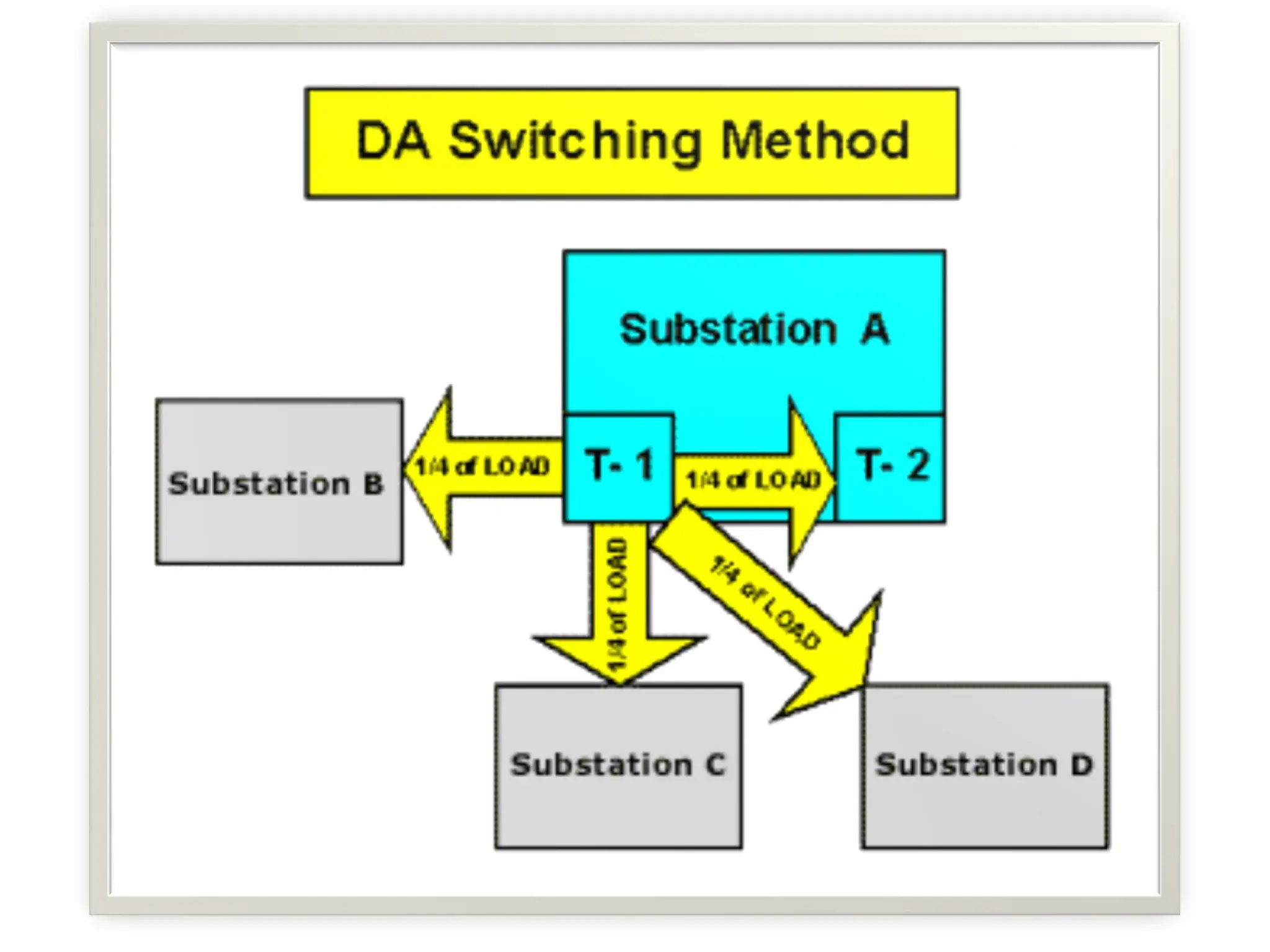
![Utility transmission and distribution systems [T&D] systems link
electric generators with end users through a network of power lines
and associated components.](https://image.slidesharecdn.com/electricalservicesunit1-240207062656-df46cabd/75/Electrical-services-WITH-WIRING-FUSES-DISTRIBUTION-SYSTEMS-5-2048.jpg)