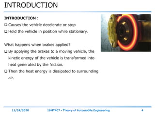
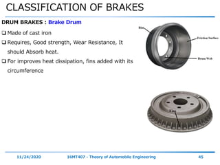
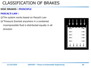
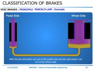
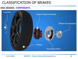
The document discusses vehicle braking systems. It begins with session objectives on understanding proper braking system selection, braking material selection for efficiency, and the role of electronics in ABS and traction control systems. It then covers topics like introduction, brake classification, ABS, and traction control systems. The introduction section defines brakes and their functions, and discusses braking principles, factors like pressure, friction, surface area, geometry. It also covers braking force calculation, weight transfer during braking, and stopping distance calculation. Drum and disc brake components and types are described. [END SUMMARY]
The document discusses vehicle steering systems. It begins with an introduction to basic steering components and principles. It then covers various topics related to steering mechanisms, including Davis and Ackerman steering mechanisms. It also discusses steering ratio, steering lock, steering gear boxes including different types, and power steering. The document provides information on key factors for proper steering such as steerability and stability.
The document describes the fabrication of a four wheel steering system for a Maruti 800 vehicle. Key points:
- The rear wheels were modified to allow for steering capability by adding a second rack and pinion steering gearbox connected to the original front gearbox via transfer rods and bevel gears.
- In rear steer mode at low speeds, the rear wheels turn in the opposite direction of the front wheels, greatly reducing the turning radius.
- Benefits of the four wheel steering system include improved vehicle handling, stability, and reduced driver fatigue over long drives due to the easier steering capability.
- The successful implementation of the system allows for increased maneuverability and stability of vehicles.
PPT on Suspension system in automobiles By Pukhraj palariyapukhraj palariya
The document discusses different types of suspension systems used in automobiles. It describes conventional suspension systems which use rigid axles connected to leaf springs. Independent suspension systems are also covered, including MacPherson strut, double wishbone, and multi-link designs which allow individual wheel movement. Air suspension uses air bags and compressors to maintain vehicle height. Hydroelastic and hydragas suspensions connect front and rear systems using fluid to better level the vehicle.
The document discusses different types of clutches used in vehicles. It describes a clutch as a mechanical device that connects and disconnects two rotating shafts to facilitate transmission of power and motion. The main types discussed are single plate clutches, multi-plate clutches, cone clutches, and centrifugal clutches. A single plate clutch uses a flywheel, pressure plate, clutch disc/plate, and release bearing. A multi-plate clutch has multiple clutch plates to transmit higher torque. A cone clutch uses a cone shape for contact rather than plates. A centrifugal clutch uses centrifugal force from rotation to engage.
This document discusses vehicle suspension systems. It begins with an introduction to suspension systems, noting their purposes of connecting the vehicle body to wheels, absorbing shocks, and maintaining road contact. It then covers various suspension system types including rigid axle and independent suspensions. Specific suspension designs are described such as double wishbone, MacPherson strut, and air suspensions. Suspension movements and the role of springs and shock absorbers are also outlined.
The document discusses various types of automobile suspension systems. It describes independent suspension systems that allow each wheel to move independently and non-independent systems where the wheels are attached to a solid axle. Common types of independent suspension include MacPherson strut suspension, wishbone suspension, and solid rear axle suspension. The document also covers suspension components like springs, shock absorbers, control arms, and sway bars. It provides advantages and disadvantages of different suspension types.
The document discusses various types of automotive braking systems. It describes the principles of hydraulic brakes, which use fluid pressure to provide equal braking force to all wheels according to Pascal's law. Drum brakes are also summarized, noting how brake shoes expand outward to contact the rotating drum and slow the wheels. Disc brakes are outlined as having pads that clamp onto a central disc attached to the wheel. Power brakes are mentioned as using engine vacuum pressure to boost braking force applied by the driver.
This document describes a project to implement a four-wheel steering system with three steering modes in a single vehicle. The system allows the vehicle to steer the front wheels normally, steer both the front and rear wheels in the same direction for improved stability at higher speeds, and steer the front and rear wheels in opposite directions to achieve a tighter turning radius at low speeds such as during parking maneuvers. The system uses gears and linkages to synchronize the steering of the front and rear wheels and allow switching between the three steering modes.
UNIT IV STEERING, BRAKES AND SUSPENSION SYSTEMS karthi keyan
Steering geometry and types of steering gear box-Power Steering, Types of Front Axle, Types of Suspension Systems, Pneumatic and Hydraulic Braking Systems, Antilock Braking System (ABS), electronic brake force distribution (EBD) and Traction Control.
The document describes two types of rear axle drives: the Hotchkiss drive and the torque tube drive. The Hotchkiss drive uses two longitudinally mounted leaf springs connected to the frame with a fixed pivot in front and swinging shackles in back. A universal joint is used at each end of the propeller shaft to accommodate changes in shaft length from spring deflection. The torque tube drive uses a tubular torque tube that encloses the propeller shaft and is bolted to the axle casing. A universal joint and ball socket joint are used to allow the propeller shaft to angle within the torque tube as the suspension moves.
This document discusses steering gear mechanisms used in vehicles. It introduces the basic principles of steering mechanisms, including that the front wheels turn to change the vehicle's direction while the back wheels remain straight. It describes two common steering mechanisms: Ackermann steering uses linkages to ensure the inside and outside wheels follow different radius circles during a turn. Davis steering is also an exact mechanism but has more sliding components, increasing wear and reducing accuracy compared to Ackermann steering. The key difference between the mechanisms is that Ackermann steering is behind the front wheels while Davis is in front, and Ackermann uses turning pairs while Davis uses sliding pairs.
An axle is a central shaft that supports rotating wheels. On vehicles, the axle can be fixed to the wheels and rotate with them, or fixed to the vehicle with the wheels rotating around it. Bearings are provided where the axle is mounted. The document discusses different types of rear axles like full floating, semi floating, and three quarter floating axles. It also discusses front axles, describing them as either dead or live axles. Finally, it lists four types of stub axles used to connect front wheels to front axles: Elliot, reversed Elliot, Lamoine, and reversed Lamoine.
This document discusses the classification and layout of automobiles. It categorizes vehicles based on factors such as load, number of wheels, fuel used, body style, transmission, drive, suspension system, engine position, and chassis type. Common passenger vehicle layouts include front-engine/front-wheel drive, front-engine/rear-wheel drive, and all-wheel drive. Components like the engine, drivetrain, and suspension are described along with their functions and materials. Methods of forced induction like turbocharging and supercharging are also introduced.
Tyres have several key functions: providing contact with the road surface, acting as the primary suspension, and allowing vehicles to brake, accelerate and steer. They are made up of plies, beads, treads and sidewalls. Radial tyres have plies that run straight across from bead to bead, providing a stable footprint. Proper tyre pressure and tread depth are important to prevent aquaplaning, where a layer of water builds up between the tyre and road surface causing loss of traction.
Torsion bars are metal bars used in automobile suspension systems that perform the function of springs. One end of the bar is fixed to the vehicle frame, while the other end is attached to components like the axle or control arm. When forces from driving cause the attached components to twist the bar, it provides resistance like a spring, absorbing shocks from the road. Torsion bars offer benefits like a soft ride, long durability, easy adjustability of vehicle height, and a compact design requiring less interior space compared to coil springs. However, they do not provide progressive spring rates and ride quality can become harsh when adjusted to maximum height. Torsion bar suspension systems are commonly used on trucks, SUVs, and military vehicles.
This document describes five main types of independent suspension systems: 1) MacPherson strut, 2) Wishbone, 3) Vertical guide, 4) Trailing link, and 5) Swinging half axles. It provides details on each system, including components, how they function, advantages and disadvantages. For example, it explains that the MacPherson strut system uses a lower wishbone and strut with shock absorber/coil spring to position the wheel. This system provides maximum engine compartment space and is commonly used in front-wheel drive cars.
The document discusses the requirements of a good steering system, including that it should be accurate, easy to handle, and require minimal effort. It also covers various aspects of wheel alignment such as camber angle, caster angle, toe-in/toe-out, and scrub radius that impact tire wear and vehicle stability. Proper wheel alignment reduces tire wear, improves gas mileage and safety, and prevents pulling to one side.
This document provides an overview of suspension systems for automobiles. It discusses the objectives of suspension systems which are to isolate the vehicle from road shocks for ride comfort and stability. It describes the main types of suspension systems including independent suspension, solid axle systems, MacPherson strut, wishbone, and trailing link. Specific suspension designs are detailed such as wishbone and MacPherson strut suspensions. Advantages and disadvantages of independent and rigid suspension systems are given. Various emerging suspension technologies are also summarized such as air, hydroelastic, and hydraulic suspensions.
The document discusses various axle systems used in vehicles. It describes the construction and function of rear axles, front axles, and stub axles. Rear axles are mounted at the rear of the vehicle and use axle shafts to transmit power from the differential to the rear wheels. Front axles provide steering action and support the front of the vehicle. Stub axles connect the wheels to the front and rear axles. The document outlines different types of rear axles including semi-floating, full-floating, and three-quarter floating designs.
The chassis consists of the engine, powertrain, brakes, steering system, and wheels mounted on a frame. The frame is the main rigid structure that forms a skeleton to hold all the major parts together. There are different types of chassis classifications including conventional, semi-forward, and full-forward control chassis based on where the engine is mounted relative to the driver's cabin. The frame can have different section types like channel, box, or tubular sections and its functions are to carry loads, support chassis components and body, and withstand various static and dynamic loads without undue deflection.
Frame and Body of Automobile
Introduction to chassis, Classification of chassis, Conventional chassis,
Semi forward chassis, Full forward chassis, Engine at the front, Engine at the rear, Engine in mid, Frame of the automobile, Function of Frame, types of frame, conventional frame, semi-integral frame, integral frame, defects in chassis, Body of the automobile, types of the body in automobile,
This presentation discusses limited slip differentials. It begins by explaining the need for limited slip differentials and how they transfer more torque to the non-slipping wheel when one powered tire slips. It then discusses the basics of how a limited slip differential works, explaining that it prevents excessive power from being allocated to the slipping wheel. The presentation goes on to describe the different principles and mechanisms by which limited slip differentials operate and distribute torque between the wheels, such as viscous couplings or clutch packs. It also outlines several common types of limited slip differentials, such as viscous, helical, torque-sensitive, and clutch-type differentials.
The document discusses the suspension system of a vehicle, describing its basic parts like control arms, ball joints, springs, and shock absorbers, and explaining how they work together to support the vehicle's weight, provide a smooth ride, and allow for steering and cornering. It also covers different types of suspension systems like independent and non-independent suspensions, as well as how to inspect and maintain key suspension components.
The document discusses the components and classification of automobiles. It describes how an automobile is a self-propelled vehicle powered by an internal combustion engine that transports passengers and goods. The key components include the power plant (engine), transmission system, auxiliaries (electric system), controls (steering and brakes), and suspension. Automobiles are classified based on their purpose, fuel type, capacity, drive, wheels/axles, suspension system, transmission, and body style. The document also discusses the different positions of the engine, including at the front, crosswise at the front, in the center, and at the back.
The suspension System of an automobile is one which separates the wheel/axle assembly from the body. The primary function of the suspension system is to isolate the vehicle structure from shocks & vibration due to irregularities of the road surface.
This document provides an overview of braking systems, including drum brakes and disc brakes. It describes the basic components and functioning of brakes, how braking converts kinetic energy to heat, and the requirements of effective braking. Drum brakes use brake shoes that expand inward or outward to create friction with the brake drum. Disc brakes use calipers and pads that clamp onto a brake disc attached to the wheel. The document compares advantages and disadvantages of drum brakes versus disc brakes.
This document discusses the steering system of vehicles. It describes the main components of a conventional linkage steering system, including the steering wheel, steering column, steering shaft, steering gearbox, pitman arm, drag link, tie rods, and knuckle arm. It also covers steering geometry concepts such as camber angle, king pin inclination, included angle, and caster angle. The steering system is designed to allow the vehicle to follow the desired path by controlling the direction of the front wheels via the hand-operated steering wheel.
This document summarizes the key components and types of manual transmission systems. It discusses the main components of a manual transmission which include the clutch, gearbox, and differential. It describes the different types of gearboxes such as constant mesh, synchromesh, and sliding mesh types. The document focuses on explaining how synchromesh gearboxes work using synchronizer rings to smoothly engage gears without grinding. In conclusion, it notes that modern synchromesh gearboxes use brass synchronizer rings to reduce wear effects in manual transmissions.
The document discusses the need for gear boxes in vehicles. It describes the various resistances that act on a moving vehicle, such as rolling resistance from friction between the tires and road, wind resistance which increases with speed, and gradient resistance from road inclines. A gear box is necessary because the engine's torque varies with speed but vehicles must be able to maintain motion over varying resistances and road conditions. By changing gears, the transmission can better match the engine's output to the demands placed on the driving wheels.
Behaviour of metals – problem for heat transfer from the automobile brakes sy...eSAT Journals
Abstract We know that, The Braking action is the use of a controlled force to reduce the speed or to stop a moving vehicle or to keep a vehicle stationary , when braking is applied, it develop friction which does the braking i.e. Kinetic energy which is converted into heat energy on the application of brake. The biggest question today is, while the driver is going to brake applied, this force is increasing by 8 times of as per horse power. For example, one vehicle has 100 hp, after the braking applied is going to reached 800 hp. Therefore, in terms of behavior of metals, some time frequent accident by means of dragging. Because, this heat is transferred through the surrounding air. The weight of the vehicle is divided on its axle, and retarding force acts on the point of road contacts towards the rear and the inertia force of gravity towards the font. Let F= retarding force, μ = coefficient of friction, W = weight of the vehicle, h = height of centre of Gravity of the vehicle from road. Therefore, F = μW (inertia force) and couple = μW × h Keywords: Braking action, horse power, inertia
Traction is the force that allows a vehicle to move forward or backward on a surface. It is the result of friction between the tires and the ground. Traction is important for vehicle safety and performance, as it affects acceleration, braking, and cornering.
The theory predicts that failure occurs when the maximum tensile stress reaches a critical value. This critical value is determined by the same factors as in shear, namely the friction angle and the cohesion of the material.
The Mohr-Coulomb failure envelope in traction is a plot of the tensile stress versus the normal stress acting on the material. The slope of the envelope still represents the friction angle, while the intercept on the tensile stress axis represents the tensile strength of the material.
factors affecting
Tire type
Surface conditions
Vehicle weight
Driving style
Road grade and slope
Temperature
tire pressure
It is obvious that vehicle weight has a linear relationship
with the energy to be dissipated (stored) and the change
in velocity required has a exponential relationship.
• Deceleration times and stopping distances vary
somewhat for all vehicles on a given road surface.
• It should then be obvious that sizing the brake system
components has critical importance with respect to the
potential vehicle velocity and the mass of the vehicle.
• Note that heavy trucks generally have greater stopping
distances as compared to typical passenger cars.
Stopping distance is the distance required to bring a vehicle to a complete stop from the moment the brakes are applied. It is the sum of the reaction distance traveled during the driver's reaction time and the braking distance. Reaction time can range from 0.3 to 1.7 seconds depending on the driver and conditions. The worst case stopping sight distance accounts for poor driving skills, low braking efficiency, and wet pavement with a perception-reaction time of 2.5 seconds. Braking performance depends on factors like vehicle weight, speed, grade, rolling resistance, aerodynamic drag, and drive line drag. Drum brakes provide better braking torque than disc brakes but are less consistent in performance.
This document summarizes a master's thesis that developed a mathematical model for predicting tyre rolling resistance. The thesis:
1) Developed a combined model for rolling resistance that accounts for vertical tyre stiffness, damping effects, and rotational aerodynamic drag.
2) Validated the model by showing it predicted a 4.8% reduction in rolling resistance coefficient for an 8.3% increase in tyre diameter, consistent with experimental data.
3) Applied the model in LeanNova's vehicle energy simulation, finding a 3.8% reduction in energy use for an electric vehicle and a 1.3% reduction in fuel use for a conventional vehicle when changing to a low rolling resistance tyre.
Validation of Hydraulic brakes for Electric VehiclesIJAEMSJORNAL
This document shows the validation of the hydraulic brakes occupied in a solar electric vehicle. The braking system evaluated consists of two components: the brake pedal with master cylinder and the wheel brake mechanism, together with the corresponding tubes or conduits and the clamping pieces. This validation is carried out through the analysis of forces, in the first part the braking force between the tire and the floor is determined; subsequently the force is calculated in the main braking system which is activated by a pedal The braking system with which it is suitable for the prototype in question is that of a Volkswagen sedan, because this brake system meets the needs of drivers in terms of efficiency.
This document discusses how tyre overload and inflation pressure affect rolling loss (resistance) and fuel consumption in automobiles. Finite element analysis was conducted on tyre models from two cars, Skoda Rapid and Ford Classic, under different load and pressure conditions. The results show that rolling loss and stress on the tyre increase with overload, leading to greater fuel consumption. Properly inflated tyres can help optimize fuel use by reducing rolling resistance. The Ford tyres performed better in the overloaded condition compared to Skoda in terms of lower stresses and fuel consumption.
Effect of Tyre Overload and Inflation Pressure on Rolling Loss (resistance) a...ijceronline
International Journal of Computational Engineering Research (IJCER) is dedicated to protecting personal information and will make every reasonable effort to handle collected information appropriately. All information collected, as well as related requests, will be handled as carefully and efficiently as possible in accordance with IJCER standards for integrity and objectivity.
The document discusses tires and the forces acting on vehicles. It provides details on different tire designs like radial and cross-ply tires. Tires transmit motive, braking, and lateral forces between the vehicle and road. These forces depend on factors like the tire construction, road conditions, and weather. The document also examines other forces like normal force, circumferential force, lateral force, braking torque, and yaw moment and how they influence vehicle motion and handling.
Analysis of Brake Biasing (Balance Bar) on BAJA (ATV) vehicleAditya Deshpande
In this report, I have done analysis of braking system for All Terrain Vehicle for BAJA competition. The report comprises thoroughly about brake biasing methods, and their uses. Here Balance bar method is discussed and analysed with mathematical formulas and subsequent conclusions are drawn.
The system was developed for VIT's Team Endurance Racing in year 2016 and successfully implemented.
I hope you find this report useful.
Do let me know your thoughts. Hit like and share this.
Aditya Deshpande
6 ijaems jul-2015-11-design of a drivetrain for sae baja racing off-road vehicleINFOGAIN PUBLICATION
This document discusses the design of a drivetrain for an off-road racing vehicle that will compete in SAE Baja competitions. It begins by outlining the importance of drivetrain design and lack of available literature on the topic. The document then evaluates the performance needs of a Baja vehicle and selects components for the powertrain including a 10 HP Briggs & Stratton engine. Calculations are shown for determining the vehicle's total tractive effort based on factors like rolling resistance, aerodynamic drag and grade resistance. Based on these calculations and the maximum adhesive force between tires and the road surface, the maximum gradient the vehicle can climb is determined to be 60%, or 30.7 degrees, without slipping.
عرض تقديمي لتصميم طريق وكيفية ابعاد الطريقssuser09e10f
This document discusses road-vehicle performance and its impact on highway engineering and design. It covers the following key points:
- Vehicle capabilities like acceleration/braking and human factors like reaction time form the basis of roadway design guidelines.
- Tractive effort and resistance are opposing forces that determine vehicle performance. The three major sources of resistance are aerodynamic, rolling, and grade.
- Aerodynamic resistance increases with speed squared and power required increases with speed cubed. Rolling resistance depends on factors like tire and surface properties. Grade resistance depends on road slope.
- Maximum tractive effort is limited by the coefficient of road adhesion and weight transfer during acceleration or braking. Braking performance is important
The document discusses the key components and principles of automotive braking systems. It explains that braking systems use friction to convert the kinetic energy of a moving vehicle into heat through the contact of brake pads or shoes with rotors or drums. The system is hydraulic, using brake fluid to transfer pressure from the brake pedal to the calipers or wheel cylinders. Drum brakes expand shoes outward to contact the inner drum surface, while disc brakes use calipers to squeeze pads against a rotor. The document also covers factors like pressure and surface area that influence braking capability.
This document discusses various types of brakes and dynamometers used in mechanical engineering. It describes shoe brakes, internally expanding shoe brakes, and how braking works when applied to rear wheels only, front wheels only, or all wheels of a vehicle. It also covers different types of dynamometers used to measure power including pony brake, rope brake, epicyclic train, belt transmission, and torsion dynamometers. Example problems are provided to calculate braking torque and distance required to stop a vehicle under different braking conditions.
This document discusses suspension systems for vehicles. It begins by defining suspension systems and their dual purposes of contributing to vehicle handling/safety while providing passenger comfort. It then describes some of the key design conflicts around suspension geometry. Specifically, it discusses how cornering forces can cause the contact patch to deform in undesirable ways. It provides examples of different suspension geometries and how they affect camber angle and contact patch deformation during turns and over bumps. The document outlines the objectives of reducing passenger discomfort, improving safety, and reducing slip during corners. It concludes by describing various properties of suspension systems that are important to consider in the design process such as spring rate, wheel rate, weight transfer, travel, damping, and more.
1) The document discusses the motion and dynamic equations for vehicles based on Newton's second law. It covers forces acting on a vehicle like rolling resistance, aerodynamic drag, and grading resistance.
2) The total driving resistance force is the sum of these forces and is equal to the tractive force required at the drive wheels.
3) The dynamic equation of vehicle motion equates the total tractive effort to the total tractive resistance force and can be used to determine acceleration.
The document discusses unmanned aerial vehicles (UAVs), including:
1) The objectives of the session are to understand the introduction, types, elements, missions, and navigation systems of UAVs.
2) UAVs consist of an air vehicle, ground control station, data link, and may have payloads like cameras. They come in various sizes and can perform missions like reconnaissance and surveillance.
3) UAV navigation systems include GPS, inertial navigation, and they may use waypoint navigation to follow a planned route.
The document discusses the benefits of exercise for mental health. Regular physical activity can help reduce anxiety and depression and improve mood and cognitive functioning. Exercise causes chemical changes in the brain that may help protect against mental illness and improve symptoms.
The document discusses alternative fuels to fossil fuels, focusing on methanol and ethanol. It provides details on:
- The production processes of methanol and ethanol, involving synthesis from other chemicals or fermentation of biomass respectively.
- The properties and modifications needed to engines to enable their use, such as increasing compression ratios, jet sizes, and pump capacities to accommodate their combustion characteristics and higher octane ratings.
- The benefits of these alternative fuels include lower emissions than gasoline and the renewable nature of ethanol.
The document discusses the vehicle body construction. It begins by introducing the objectives of the session which are to understand how vehicle parts form the body and give an aesthetic view to consumers. It then covers various topics related to vehicle body design including the importance of design, types of bodies, body construction components, body materials, and aerodynamics. The document focuses on the components that make up the vehicle body, how the body is constructed, and the purpose of key parts like doors, hood, seats, and other interior and exterior parts.
The document discusses turbochargers, including:
- A turbocharger uses the waste heat from exhaust gases to power a turbine, which spins a compressor to force more air into the engine cylinders, increasing power.
- It has a turbine section, compressor section, bearing housing, and wastegate valve. The bearing allows the turbine and compressor wheels to spin at high speeds while absorbing vibrations. The wastegate diverts some exhaust to control boost pressure.
- During acceleration, more exhaust flow spins the turbine and compressor faster, supplying more air/fuel to the engine for more power. The wastegate manages boost pressure to prevent damage from excessive pressure rises.
The document discusses catalytic converters, which are emission control devices that convert toxic gases from vehicle exhaust into less toxic pollutants. It describes the functions of catalytic converters, their construction using a ceramic core with precious metal catalysts, and how they work to oxidize carbon monoxide and hydrocarbons while also reducing oxides of nitrogen through redox reactions. The document differentiates between two-way catalytic converters, which control carbon monoxide and hydrocarbons, and three-way catalytic converters, which also control oxides of nitrogen emissions. Three-way catalytic converters are highlighted as the most effective at reducing the three main pollutants from vehicle exhaust.
The document discusses vehicle frames, including their objectives, types, construction methods, and loads. It begins by outlining the session objectives of understanding frame material selection, loads on frames, and frame construction types. It then defines frames as the main chassis component that supports other parts. The key types discussed are conventional, semi-integral, and integral frames. Materials covered include steel alloys, with details on channel, box, tubular, and I-beam cross sections. Loads on frames from acceleration, braking, impacts and more are also summarized.
The function of an Electronic ignition system is to produce the spark to ignite the air-fuel mixture in a timely manner for maintaining the effective combustion
The document discusses various electronic fuel injection systems for compression ignition (CI) engines. It begins by explaining the principles of CI engines and how they rely on high temperatures from compression to ignite fuel rather than a spark plug. It then categorizes CI engine injection systems as using either compressed air or high-pressure liquid fuel directly. Various common electronic systems are described in detail, including individual pump systems, common rail, and unit injector systems. The document focuses on explaining the working of the modern common rail system, describing its components and fuel injection process.
Implementing ELDs or Electronic Logging Devices is slowly but surely becoming the norm in fleet management. Why? Well, integrating ELDs and associated connected vehicle solutions like fleet tracking devices lets businesses and their in-house fleet managers reap several benefits. Check out the post below to learn more.
Welcome to ASP Cranes, your trusted partner for crane solutions in Raipur, Chhattisgarh! With years of experience and a commitment to excellence, we offer a comprehensive range of crane services tailored to meet your lifting and material handling needs.
At ASP Cranes, we understand the importance of reliable and efficient crane operations in various industries, from construction and manufacturing to logistics and infrastructure development. That's why we strive to deliver top-notch solutions that enhance productivity, safety, and cost-effectiveness for our clients.
Our services include:
Crane Rental: Whether you need a crawler crane for heavy lifting or a hydraulic crane for versatile operations, we have a diverse fleet of well-maintained cranes available for rent. Our rental options are flexible and can be customized to suit your project requirements.
Crane Sales: Looking to invest in a crane for your business? We offer a wide selection of new and used cranes from leading manufacturers, ensuring you find the perfect equipment to match your needs and budget.
Crane Maintenance and Repair: To ensure optimal performance and safety, regular maintenance and timely repairs are essential for cranes. Our team of skilled technicians provides comprehensive maintenance and repair services to keep your equipment running smoothly and minimize downtime.
Crane Operator Training: Proper training is crucial for safe and efficient crane operation. We offer specialized training programs conducted by certified instructors to equip operators with the skills and knowledge they need to handle cranes effectively.
Custom Solutions: We understand that every project is unique, which is why we offer custom crane solutions tailored to your specific requirements. Whether you need modifications, attachments, or specialized equipment, we can design and implement solutions that meet your needs.
At ASP Cranes, customer satisfaction is our top priority. We are dedicated to delivering reliable, cost-effective, and innovative crane solutions that exceed expectations. Contact us today to learn more about our services and how we can support your project in Raipur, Chhattisgarh, and beyond. Let ASP Cranes be your trusted partner for all your crane needs!
The Octavia range embodies the design trend of the Škoda brand: a fusion of
aesthetics, safety and practicality. Whether you see the car as a whole or step
closer and explore its unique features, the Octavia range radiates with the
harmony of functionality and emotion
Ever been troubled by the blinking sign and didn’t know what to do?
Here’s a handy guide to dashboard symbols so that you’ll never be confused again!
Save them for later and save the trouble!
Fleet management these days is next to impossible without connected vehicle solutions. Why? Well, fleet trackers and accompanying connected vehicle management solutions tend to offer quite a few hard-to-ignore benefits to fleet managers and businesses alike. Let’s check them out!
Digital Fleet Management - Why Your Business Need It?
Braking system
1. SRI KRISHNA COLLEGE OF ENGINEERING AND TECHNOLOGY
DEPARTMENT OF MECHATRONICS ENGINEERING
Session: Vehicle Braking System
11/24/2020 16MT407 - Theory of Automobile Engineering 1
MODULE 1
2. SESSION OBJECTIVES
11/24/2020 16MT407 - Theory of Automobile Engineering 2
On the completion of this session, the students might
be able to understand,
Proper selection of Braking system for your vehicle.
Good chosen of braking material for better braking
efficiency.
Role of electronics in Anti lock Braking system &
Traction control system.
3. Topics
Introduction
Classification of Brakes
Ant locking braking system
Traction Control System
11/24/2020 16MT407 - Theory of Automobile Engineering 3
4. INTRODUCTION
11/24/2020 16MT407 - Theory of Automobile Engineering 4
INTRODUCTION :
Causes the vehicle decelerate or stop
Hold the vehicle in position while stationary.
What happens when brakes applied?
By applying the brakes to a moving vehicle, the
kinetic energy of the vehicle is transformed into
heat generated by the friction.
Then the heat energy is dissipated to surrounding
air.
5. INTRODUCTION
11/24/2020 16MT407 - Theory of Automobile Engineering 5
Function of brakes : Purpose
Stop the moving vehicle in minimum possible
time.
Controls the speed, in turning & Crowded
places.
Holds the vehicle in stationary position,
without the presence of drive, after it has
been brought to stop.
6. INTRODUCTION
11/24/2020 16MT407 - Theory of Automobile Engineering 6
Principle of Brake Operation:
Generally Kinetic energy provided by the engine,
keeps its accelerate from standstill to a desired speed.
While applying brake, the energy of motion or Kinetic
energy is converted into heat energy generated by the
friction.
Kinetic energy of the vehicle during braking is,
𝐾 𝐸 =
1
2
𝑚 𝑢2
− 𝑣2
=
𝑊 𝑢2 − 𝑉2
2𝑔
∴ 𝑊 = 𝑚𝑔 𝑜𝑟 𝑚 =
𝑤
𝑔
w = Weight of the vehicles N = mg
m = Mass of the vehicle
u = Initial velocity of the vehicle m/s
V = Final Velocity of the vehicle m/s
g = acceleration due to Gravity = 9.81 m/s2
4 time KE = 4 times Brake Power
7. INTRODUCTION
11/24/2020 16MT407 - Theory of Automobile Engineering 7
Principle of Brake Operation: Frictional Force?
Opposes the vehicle motion
Consume power & Produce heat.
It occurs b/n Tyre & Road surface when the wheels
are locked by brakes.
To stop vehicle, it mainly rely on co-efficient of friction
b/n the contacting surfaces.
The amount of energy absorbed by the brakes
depends up-on
Pressure exerted on brakes
Co-efficient of friction of brake material
Brake surface area
Brake geometry.
8. INTRODUCTION
11/24/2020 16MT407 - Theory of Automobile Engineering 8
Factors Governing Braking: Pressure exerted on the braking surface
When the pressure applied to two
frictional surfaces, then they grip each
other harder and resist any movement
between them.
9. INTRODUCTION
11/24/2020 16MT407 - Theory of Automobile Engineering 9
Factors Governing Braking: Coefficient of friction b/n braking surface
On the same surface, for moving different
material required different force.
Each material has different frictional
characteristics or Coefficient of friction (μ).
If “μ” is too high – Brakes may be grab or
cause wheel to slide.
If “μ” is too low – too much pressure is
required on brake pedal to stop the
vehicle.
𝜇 =
𝐹
𝑅 𝑁
F – Tangential braking force or frictional force acting at the contact surface block & Wheel
RN – Normal Reaction
10. INTRODUCTION
11/24/2020 16MT407 - Theory of Automobile Engineering 10
Factors Governing Braking: Frictional Contact Surface
The bigger brakes stops a vehicle more quickly than
the smaller brakes used on the same vehicle.
Four wheel brakes stop a vehicle faster than a two
wheel brakes on same vehicle.
11. INTRODUCTION
11/24/2020 16MT407 - Theory of Automobile Engineering 11
Factors Governing Braking: Brake Geometry (Heat dissipation Capability)
During braking, friction cause heat generation on Pad
& Disc.
It should be properly dissipated by air. (Absorb by air)
Mass & Potential speed of the vehicle determine the
size of braking mechanism and the friction surface
area of the pad or shoe.
No proper heat dissipation - leads to brake fade during
hard or continuous braking.
What will be happen?
Lining pad or shoe become glazed
Disc & Drum becomes hardened
Now the μ reduced, leads to excessive pressure must
be applied to produce desired braking effect.
12. INTRODUCTION
11/24/2020 16MT407 - Theory of Automobile Engineering 12
Braking Force: FB
It is the force of resistance applied to stop the vehicle
or reduce the speed..
It depends on weight of a vehicle & rate of
deceleration which it is stopped.
Neglecting the following thing FB Calculated.
Air & gradient resistance
𝐹𝐵 =
𝑊. 𝑎
𝑔
𝑎 =
𝑔 . 𝐹𝐵
𝑊
W – Weight of the Vehicle
a – Rate of Deceleration
g – Acceleration due to gravity = 9.81 m/s2
Sum of Braking forces of all wheel equal to weight of the vehicle.
13. INTRODUCTION
11/24/2020 16MT407 - Theory of Automobile Engineering 13
Braking Force: FB
The limiting value of the braking force depends upon
the adhesion of wheel on the road surface.
The ratio of adhesion to the weight of the vehicle is
called the Coefficient of friction.
𝜇 =
𝐹𝐵
𝑊
𝑜𝑟 𝜇 =
𝑎
𝑔
14. INTRODUCTION
11/24/2020 16MT407 - Theory of Automobile Engineering 14
Maximum Retardation Point
Brakes applied – Wheels will either roll or skid.
Depends upon the relative value of Friction b/n
braking surface and friction b/n the tyre & road.
Jamming of braking surface, increase the friction &
cause wheel skid & more tyre wear.
The maximum retardation is reached means, wheel
lock condition during braking.
At this point friction/n Braking surface should equal to
the friction b/n Tyre & Road contact surface.
In case the friction b/n braking surface is more than
the friction b/n tyre & road, then the brake will lock &
the tyre will start skidding.
15. INTRODUCTION
11/24/2020 16MT407 - Theory of Automobile Engineering 15
Weight Transfer During Braking:
Effective braking force occurs on the
Ground
During Braking vehicle weight & Kinetic
energy of the vehicle act through its center
of gravity.
When applying braking to moving vehicle,
It experience pitching.
This tendency of the vehicle is known as
“Brake dip”
Height of Center of gravity of vehicle
above ground level, in relation to the
wheel base & suspension characteristics.
16. INTRODUCTION
11/24/2020 16MT407 - Theory of Automobile Engineering 16
Weight Transfer During Braking:
When applying brake, results in increase
weight on front wheel & decrease weight
on rear wheel.
Therefore, front brakes absorbs more
kinetic energy than the rear brakes.
Maximum amount of weight transfer
𝑊𝑇 =
𝜇 ℎ 𝑊
𝑏
When deceleration of vehicle is considered
𝑊𝑇 =
𝜇 ℎ 𝑎 𝑊
𝑏. 𝑔
WT – Weight transferred.
μ – Coefficient of friction
h – Height of center of gravity
from the ground level.
W – Gross weight of the vehicle
b – Wheel Base
a – deceleration of the vehicle
g – Acceleration due to gravity
17. INTRODUCTION
11/24/2020 16MT407 - Theory of Automobile Engineering 17
Weight Transfer During Braking:
During braking, weight is added to the
static weight on the front wheels and
subtracted from the static weight on the
rear wheels.
The front wheel static weight is normally
55% of the vehicle weight.
The front brakes are designed to absorb
extra braking effort by selecting suitable
braking system.
Because, front wheel locks ahead of rear &
cause the vehicle to go straight & not to
spin.
18. INTRODUCTION
11/24/2020 16MT407 - Theory of Automobile Engineering 18
Stopping Distance:
Distance required to stop a
vehicle during application of the
brake
By considered a 100% Brake
efficiency, the stopping distance
may calculated.
𝑆 = 𝑢. 𝑡 −
1
2
𝑎. 𝑡2
𝑉2 − 𝑈2 = −2𝑎𝑠
V = 0 (at end of stop)
𝑆 = 𝑢2/2𝑎
s = Distance moved by the vehicle in m
u = Initial Velocity of the vehicle in m/s
v = Final velocity of the vehicle in m/s
t = Stopping time in s
a = Deceleration of the vehicle in m/s2
19. INTRODUCTION
11/24/2020 16MT407 - Theory of Automobile Engineering 19
Braking Efficiency:
Ratio of braking force produced to the weight of
the vehicle.
ȠB =
𝐹 𝐵
𝑊
× 100
Generally less than 100% because of
insufficient road adhesion & Ineffective braking
system.
Braking efficiency equal to Coefficient of friction.
If ȠB = 100% means, μ = 1
Total braking force produced at wheel = equal
to the vehicle weight.
100% brake efficiency lead injury to passenger
It generally vary from 50 to 80%
20. CLASSIFICATION OF BRAKES
11/24/2020 16MT407 - Theory of Automobile Engineering 20
Classification of Brakes: According to the purpose of the brakes
Service Brakes/Foot Brakes :
Operated by foot pedal
Used while in vehicle moving to stop it.
21. CLASSIFICATION OF BRAKES
11/24/2020 16MT407 - Theory of Automobile Engineering 21
Classification of Brakes: According to the purpose of the brakes
Hand Brake or Parking Brake :
Operated by Brake lever or Pedal
Used to hold the vehicle in position
while stationary
Helps in parking, Prevent vehicle
rolling @ Different road gradient/Fast
blowing wind.
Act as Emergency brake, while service
brakes fail or prove ineffective.
22. CLASSIFICATION OF BRAKES
11/24/2020 16MT407 - Theory of Automobile Engineering 22
Classification of Brakes: According to the construction of brake
Drum Brakes Disc Brakes
23. CLASSIFICATION OF BRAKES
11/24/2020 16MT407 - Theory of Automobile Engineering 23
Classification of Brakes: According to the Method of operation
Mechanical brakes
Hydraulic Brakes
Vacuum Brakes
Air Brakes
Electric Brakes
24. CLASSIFICATION OF BRAKES
11/24/2020 16MT407 - Theory of Automobile Engineering 24
DRUM BRAKES : Components
Brake Drum : Acts as a braking surface
on wheel side
Wheel Hub : The part which Wheel &
Brake drum is attached
25. CLASSIFICATION OF BRAKES
11/24/2020 16MT407 - Theory of Automobile Engineering 25
DRUM BRAKES : Components
Back Plate : Holds all the brake
components together
Brake Shoe : This will be pushed against
the inner surface of the drum
26. CLASSIFICATION OF BRAKES
11/24/2020 16MT407 - Theory of Automobile Engineering 26
DRUM BRAKES : Components
Brake Lining :
Provides friction b/n Brake shoe &
Inner surface of drum.
Causes to slow down the wheel
Hold Down Spring : Holds the Brake
shoe towards the Back plate
27. CLASSIFICATION OF BRAKES
11/24/2020 16MT407 - Theory of Automobile Engineering 27
DRUM BRAKES : Components
Retaining Spring : Retaining the brake
shoe to its Resting position
Wheel Cylinder : Hydraulic Part which
pushes the brake shoe
28. CLASSIFICATION OF BRAKES
11/24/2020 16MT407 - Theory of Automobile Engineering 28
DRUM BRAKES : Components
Self Adjuster Mechanism :
Modern drum brakes uses self adjuster
mechanism
Which means when the lining wear's
out, the system aligning the brake shoe
to keep the clearance b/n drum surface
& Brake lining
29. CLASSIFICATION OF BRAKES
11/24/2020 16MT407 - Theory of Automobile Engineering 29
DRUM BRAKES : Working
To operate the brake, the brake pedal is
pressed,
Brake shoes are pushed outwards,
So the lining is forced against the
drum,
The force comes from hydraulic wheel
cylinder or from the mechanical linkage
of the parking brake.
When the brake pedal is released, it
causes the brake shoes to return to
their original position, through the
action of the brake springs.
30. CLASSIFICATION OF BRAKES
11/24/2020 16MT407 - Theory of Automobile Engineering 30
DRUM BRAKES : Leading & Trailing Shoe
Shoe which extends in the same direction as
the rotation of the brake drum is known as
leading shoe.
Shoe which extends in opposite direction is
known as trailing shoe.
Leading shoe pushed up against the inside of
the drum, and pulled along by its rotation,
causing it to expand out wards.
Now brake shoe push harder against the drum
by applying even stronger braking force
Known as self-servo action or self energization
action
31. CLASSIFICATION OF BRAKES
11/24/2020 16MT407 - Theory of Automobile Engineering 31
DRUM BRAKES : Leading & Trailing Shoe
Trailing shoe pushed by the brake drum &
apply weaker braking force.
During trailing shoe pressed against the drum,
the friction caused by the drum rotation
subjects the shoe to forces which are centering
on the anchoring pins.
Those forces press the shoe inside.
Thus weakening the pressure on drum.
Now drum rotation de-energizes the trailing
shoe by forcing it inside.
In this way the drum speed reduced & Stopped
32. CLASSIFICATION OF BRAKES
11/24/2020 16MT407 - Theory of Automobile Engineering 32
DRUM BRAKES : Types
Leading & Trailing shoe Type :
Pivoted at bottom by anchor
Opened by Wheel cylinder at
Top.
One leading & Trailing shoe
provide constant braking force at
all time to stop vehicle.
Used in Small rear wheel drive
cars & Front wheel drive cars
33. CLASSIFICATION OF BRAKES
11/24/2020 16MT407 - Theory of Automobile Engineering 33
DRUM BRAKES : Types
Two Leading Shoe : Single acting type
Unidirectional wheel cylinders are
mounted in top & bottom of the brake
drum.
Both shoe can have self servo action
during vehicle forwarding
High degree of braking force is generated.
But it will reduced during vehicle
reversed.
Because now both the shoe experience
trailing
Used in front brakes, before the use of
disc brakes
34. CLASSIFICATION OF BRAKES
11/24/2020 16MT407 - Theory of Automobile Engineering 34
DRUM BRAKES : Types
Two Leading Shoe : Double acting type
Bidirectional wheel cylinders are
mounted on the top & bottom of the
brake shoes
Provide high degree of braking force @
forward & Reverse direction of Vehicle.
35. CLASSIFICATION OF BRAKES
11/24/2020 16MT407 - Theory of Automobile Engineering 35
DRUM BRAKES : Types
Duo Servo Type:
Similar to Leading & Trailing shoe type
Here brake shoes are not connected to backing
plate,
Rather they are connected each other by a shoe
adjuster
Advantages is both shoe act as a leading shoe.
Disadvantage, does not provide constant braking
force
36. CLASSIFICATION OF BRAKES
11/24/2020 16MT407 - Theory of Automobile Engineering 36
DRUM BRAKES : Brake Shoes
Made of two parts of pressed steel
Shoe rim & Shoe web
Shoe rim curved profile closely match with drum inner surface
Brake lining is attached to the rim Surface
It has series of bent areas on the edges, where the shoe rest against the
backing plate
Shoe web welded to the rim for
reinforcement to rim
The other part of the brake drum like anchor,
return spring, parking brake attachment, and
adjusting mechanism are attached to the
shoe web
Al – Shoe - good Heat dissipation, less weight
37. CLASSIFICATION OF BRAKES
11/24/2020 16MT407 - Theory of Automobile Engineering 37
DRUM BRAKES : Brake Lining (Bonding Attachment)
Made up of Friction material.
Two methods followed to attached with brake shoe.
Bonded lining is attached to shoe by high temperature
adhesive.
Procedure
First cleaning the break shoes
Lining surface roughened by sanding
The adhesive then applied to both liner & Shoe
Then placed into the high temperature oven (150oC
to 200oC
After curing the brake shoe is removed & allowed to
cool
Bonded lining is preferable
38. CLASSIFICATION OF BRAKES
11/24/2020 16MT407 - Theory of Automobile Engineering 38
DRUM BRAKES : Brake Lining (Riveting Attachment)
Attached to the Brake shoe by a series of Brass or
Aluminum rivets.
The rivets are pass through countersunk hole on lining
The rivets are flattened inside the shoe rim to hold the
lining tightly in place
39. CLASSIFICATION OF BRAKES
11/24/2020 16MT407 - Theory of Automobile Engineering 39
DRUM BRAKES : Brake Lining Material
Function :
Designed to produce heat from friction.
As it rubs against the rotating drum surface.
Also known as friction material.
Not to cause excessive wear to drum & Disc surface.
Able to operate at high temperatures without failure.
Made by Organic or metallic material.
40. CLASSIFICATION OF BRAKES
11/24/2020 16MT407 - Theory of Automobile Engineering 40
DRUM BRAKES : Organic Lining
Moulded Type :
Made of mixed compound asbestos, filler material, Powdered resin.
Asbestos – Silicate mineral called as rock forming minerals
Form from Serpentinite/Amphibole rocks
Filler material - Improves coefficient of friction & Gives good
bonding b/n asbestos & resin
To reinforce the brake lining.
Generally Barium sulfate (barytes) used as filler material.
Resin – Mixtures of organic compounds.
BLR 140 - melamine resin add with Brake lining to improve
thermal & mechanical properties of friction material
Melamine formaldehyde – organic compound (Thermosetting
plastic)
Asbestos
Serpentinite
Rocks
41. CLASSIFICATION OF BRAKES
11/24/2020 16MT407 - Theory of Automobile Engineering 41
DRUM BRAKES : Organic Lining
Moulded Type :
The mixture organic compound is Moulded in dies to
form into shape & is placed under heat & pressure until
hard
To get a state like Board
After it will cut into individual segments & attached with
Brake shoe
42. CLASSIFICATION OF BRAKES
11/24/2020 16MT407 - Theory of Automobile Engineering 42
DRUM BRAKES : Organic Lining
Woven Type :
Form from strands of Asbestos & Threads of Other
material
And impregnated (Soak) with rubber compound
To form organic lining for brake shoe.
43. CLASSIFICATION OF BRAKES
11/24/2020 16MT407 - Theory of Automobile Engineering 43
DRUM BRAKES : Metallic Lining
Sintering Method :
Process of compacting & Forming of solid mass of material by heat or pressure,
without melting it to the point of liquefaction.
Made of sintered metal has a composition of fine powdered Copper or iron,
Graphite and some amount of inorganic fillers and friction modifier
Inorganic Fillers – Silicon Carbide,Clacium carbonare, Dolomite, etc
Graphite (Crystalline Carbon), Carbon – Friction modifier
Finally lubricating oil is added for avoid segregation of different materials.
Required form of Lining is formed by some special process like heat treatment,
etc.
Frictional qualities is more constant than organic lining
It can be used in Police cars, Fire brigade vehicle, Sport cars
44. CLASSIFICATION OF BRAKES
11/24/2020 16MT407 - Theory of Automobile Engineering 44
DRUM BRAKES : Backing Plate
It is the base unit, where all the component is
attached,
It is fixed with rear axle or steering Knuckle.
The anchor pin is a steel pin welded or riveted solidly
to the backing plate or threaded into steering
Knuckle through the backing plate
It has various projection, where it holds the position
of Brake shoe & Drum.
It also contains holes and bosses for attaching wheel
cylinder, shoe hold-down spring, and parking brake
lever
45. CLASSIFICATION OF BRAKES
11/24/2020 16MT407 - Theory of Automobile Engineering 45
DRUM BRAKES : Brake Drum
Made of cast iron
Requires, Good strength, Wear Resistance, It
should Absorb heat.
For improves heat dissipation, fins added with its
circumference
46. CLASSIFICATION OF BRAKES
11/24/2020 16MT407 - Theory of Automobile Engineering 46
DISC BRAKES : PRINCIPLE
PASCAL’S LAW :
The system works based on Pascal’s Law
“Pressure Exerted anywhere in a contained
incompressible fluid is distributed equally in all
direction
50. CLASSIFICATION OF BRAKES
11/24/2020 16MT407 - Theory of Automobile Engineering 50
DISC BRAKES : COMPONENT
Disc Rotor :
Part of the disc brake
Squeeze by Brake pads
During braking, heat will generate
because of friction,
That decelerate the wheel
Stud holes helps to dissipate heat
from disc by allowing more air
into it.
Optimum cooling performance is
achieved.
52. CLASSIFICATION OF BRAKES
11/24/2020 16MT407 - Theory of Automobile Engineering 52
DISC BRAKES : COMPONENT
Housing Part :
Also called as Caliper
Mounted on steering Knuckle
Through Banjo Fitting The fluid
enters into the housing
Causes the piston to come out
with great force
To squeeze the pads against the
Rotating Disc
Comes in two types
Floating Caliper design
Fixed caliper Design
53. CLASSIFICATION OF BRAKES
11/24/2020 16MT407 - Theory of Automobile Engineering 53
DISC BRAKES : COMPONENT
Housing Part : Floating Caliper Type
Either comes with one piston or two
piston
During outer pad squeeze the disk,
the caliper can slide along vehicle
frame.
In general floating type single piston
is used on light cars.
54. CLASSIFICATION OF BRAKES
11/24/2020 16MT407 - Theory of Automobile Engineering 54
DISC BRAKES : COMPONENT
Housing Part : Fixed Caliper Type
Caliper solidly fixed to the steering
Knuckle.
It uses a pair of piston.
Located on both side of caliper
providing equal force each pad.
It’s also incorporate one or two
piston on each side (depends on
vehicle)
The inboard piston applies pressure
to the inner pad
Outboard piston applies pressure to
the outer pad
55. CLASSIFICATION OF BRAKES
11/24/2020 16MT407 - Theory of Automobile Engineering 55
DISC BRAKES : COMPONENT
Brake Pad :
Consists of a block of friction material attached to
a stamped steel backing plate.
The brake pad material is bonded to the backing
plate with a high temperature adhesive.
A slit is provided on the face of the pad to indicate
the allowable limit of the pad wear.
It also provide a path for brake dust and gas to
escape .
56. CLASSIFICATION OF BRAKES
11/24/2020 16MT407 - Theory of Automobile Engineering 56
DISC BRAKES : COMPONENT
Brake Pad wear indicator :
Some times attached to the one of the pads.
Simple steel plate
Helps the drive to notice about pad replaceable
time
Via a screeching Noise.
If he not notice it properly, leads to irreparable
damage to disc.
57. CLASSIFICATION OF BRAKES
11/24/2020 16MT407 - Theory of Automobile Engineering 57
DISC BRAKES : COMPONENT
Pad to Disc Clearance Adjustment :
Similar to self adjuster mechanism in drum brake.
Automatic adjustment of the pad to disc clearance
is done whenever the brake is operated
A deformable seal is placed inside the machined
groove in the housing.
60. CLASSIFICATION OF BRAKES
11/24/2020 16MT407 - Theory of Automobile Engineering 60
Brake Fade :
Brake drums and discs are forced to absorb
a significant amount of heat during braking..
It describes heat generation is faster rate
than a capable of heat dissipation to
atmospheric air.
Happen during repeated hard stops,
Overheating
Leads to Ineffective braking or even brake
failure.
Two causes for brake fade
Mechanical fade
Lining Fade
61. CLASSIFICATION OF BRAKES
11/24/2020 16MT407 - Theory of Automobile Engineering 61
Brake Fade :
Mechanical Fade:
Due to brake drum over heats & expand
away from the brake lining.
Results increased brake pedal force during
travel.
Lining Fade:
Affects both drum & Disc brake.
Affects when the friction material overheats
to the point where the co-efficient of friction
drops off.
In this moment Friction is reduced and
brake ability to convert added heat is
reduced
62. CLASSIFICATION OF BRAKES
11/24/2020 16MT407 - Theory of Automobile Engineering 62
Disc Brake vs. Drum Brake :
DISC BRAKE Drum Brake
Non – energized, Non servo Brakes Self energizing , Servo brakes
Brake pad pressure is directly proportional to
brake pedal pressure
Not directly proportional
More stable Less stable
Brake disc generally stays cleaner
Drum collects all the contaminants due to
centrifugal force
Remains cooler under repeated severe
braking
Heat increase under repeated severe braking
Clamping action of disc brake pad causes no
distortion of the disc
Spreading action of drum brake shoes cause
the drum to elongate into elliptical or oval
shape
Brake pad can easily replaced Not be easily replaced
More cost Less cost
High pedal pressure is required No high pedal pressure required
Difficult to install parking brake Easy to install parking brake
63. CLASSIFICATION OF BRAKES
11/24/2020 16MT407 - Theory of Automobile Engineering 63
Hydraulic Braking System:
Brakes which are operated by means of
hydraulic pressure known as Hydraulic Brakes
Works on the principle called “Pascal’s Law”
All modern automobile brake systems use a
hydraulic system to transmit the forces from
the brake pedal to brake shoe or Brake pad
Main Components :
Brake Pedal
Master Cylinder
Drum Brakes – PCV & Wheel Cylinder
Disc Brakes
64. CLASSIFICATION OF BRAKES
11/24/2020 16MT407 - Theory of Automobile Engineering 64
Hydraulic Braking System: Master Cylinder
Major components of Hydraulic braking system.
Converts the pressure applied to the brakes into
hydraulic pressure.
Maintains the constant volume of the fluid in the brake
lines, since it has a reservoir.
Reservoir cap equipped with float sensor about the fluid
level in the tank
Master Cylinder
Single Master
Cylinder
Tandem Master
cylinder
65. CLASSIFICATION OF BRAKES
11/24/2020 16MT407 - Theory of Automobile Engineering 65
Hydraulic Braking System: Master Cylinder
Single Master Cylinder : Construction
Consists two portion, Namely Cylinder &
Reservoir.
In reservoir Filer cap contains air vent, so
fluid can expand & Contract and still at
atmospheric pressure.
Main cylinder has piston, Primary cup &
Secondary rubber cups, Return Spring,
Outlet check valve & a rubber seat.
Rubber boot covers the push rod end of
the cylinder, to prevent dirt into the
cylinder.
66. CLASSIFICATION OF BRAKES
11/24/2020 16MT407 - Theory of Automobile Engineering 66
Hydraulic Braking System: Master Cylinder
Single Master Cylinder : Working
i. When brake pedal is pressed?
Piston inside the cylinder forces the
fluid into the brake line.
Fluid pressure built up in the brake
system.
The fluid pressure acts at the piston in
the wheel cylinder or caliper.
The outside movement of piston
causes brake pad to come into contact
with brake shoe & disc
There by brakes applying
67. CLASSIFICATION OF BRAKES
11/24/2020 16MT407 - Theory of Automobile Engineering 67
Hydraulic Braking System: Master Cylinder
Single Master Cylinder : Working
i. When brake pedal is Released?
Piston return spring move the piston
very rapidly.
This cannot compensate by fluid
movement.
So partial vacuum creates inside the
cylinder.
Now fluid from intake port moves via
hole in the piston & fill the vacuum in
the cylinder.
In contrast, fluid pressure in the line
open the outlet check valve.
68. CLASSIFICATION OF BRAKES
11/24/2020 16MT407 - Theory of Automobile Engineering 68
Hydraulic Braking System: Master Cylinder
Tandem Master Cylinder :
Construction
Tandem means – inline
Master cylinder contains two
piston in it’s inline to each other
with in a single cylinder.
Primary piston contains two
rubber cups.
Secondary piston contains three
rubber cups.
Secondary cups on secondary
piston slightly different.
69. CLASSIFICATION OF BRAKES
11/24/2020 16MT407 - Theory of Automobile Engineering 69
Hydraulic Braking System: Master Cylinder
Tandem Master Cylinder :
Working
i. When brake pedal is
pressed?
Primary piston operation is
same as single master
cylinder.
Secondary piston operates
by pressure built up in the
primary section
Here the hydraulic
pressure delivered to two
independent brake lines
70. CLASSIFICATION OF BRAKES
11/24/2020 16MT407 - Theory of Automobile Engineering 70
Hydraulic Braking System: Master Cylinder
Tandem Master Cylinder :
Working
i. When brake pedal is
released?
Primary piston returns to
the retaining ring at the
end of the cylinder.
Primary & Secondary
spring length & strength
determines the secondary
piston position during
returning.
71. CLASSIFICATION OF BRAKES
11/24/2020 16MT407 - Theory of Automobile Engineering 71
Hydraulic Braking System: Master Cylinder
Tandem Master Cylinder :
Working
i. When brake pedal is
released?
The piston stop bolt
ensure the secondary
piston return & its position
after brake release.
72. CLASSIFICATION OF BRAKES
11/24/2020 16MT407 - Theory of Automobile Engineering 72
Hydraulic Braking System: Master Cylinder
Tandem Master Cylinder :
Advantage:
If any leakage on any one
piston side also ensure the
brake pressure on non failure
side.
Front wheel drive cars use a
diagonal split system.
One piston supply pressure for
front right brake & rear left
brake
Similarly other piston supply
pressure in opposite manner.
73. CLASSIFICATION OF BRAKES
11/24/2020 16MT407 - Theory of Automobile Engineering 73
Hydraulic Braking System: Master Cylinder
Tandem Master Cylinder :
Advantage:
In diagonal split system ensure
the 50% of the braking power
on one line, even failure in the
system.
74. CLASSIFICATION OF BRAKES
11/24/2020 16MT407 - Theory of Automobile Engineering 74
Hydraulic Braking System: Proportional control valve (PCV)
During braking, the weight of the
vehicle transfer to front portion of
the vehicle.
Increase load on front portion,
makes the front brakes less prone
to locking.
Meanwhile, rear wheel side load is
reduced, which increases the
possibility to lock the rear wheels.
It causes the rear wheel to skid &
the vehicle is spin.
The PCV is provided to reduce & maintain the rear brake pressure & maintain
with its limit.
75. CLASSIFICATION OF BRAKES
11/24/2020 16MT407 - Theory of Automobile Engineering 75
Hydraulic Braking System: Proportional control valve (PCV)
Construction :
Input port receive brake fluid from
master cylinder.
A plunger actuated valve body held
open by spring force.
76. CLASSIFICATION OF BRAKES
11/24/2020 16MT407 - Theory of Automobile Engineering 76
Hydraulic Braking System: Proportional control valve (PCV)
Working :
When apply brake pedal, the brake
fluid pressure is transmitted to the
rear brakes via PCV
77. CLASSIFICATION OF BRAKES
11/24/2020 16MT407 - Theory of Automobile Engineering 77
Hydraulic Braking System: Proportional control valve (PCV)
Working :
When pressure on rear brake line
increase.
It over come the spring force inside
the valve.
& make it move downward.
Now the plunger is contact with the
lip seal.
Closing off the brake line.
In this moment equal pressure on
Master’s & Rear wheel brake’s
No pressure is transmitted to the
rear wheel
78. CLASSIFICATION OF BRAKES
11/24/2020 16MT407 - Theory of Automobile Engineering 78
Hydraulic Braking System: Proportional control valve (PCV)
Working :
When pressure is increased in
master side.
Plunger is pushed up against the
spring
Open valve to rear brake line.
Now pressure is transmitted to rear
line’s.
This cycle is continued & prevent
pressure surges on rear side
Also prevent wheel lock
For maintain the stability of the
vehicle.
79. CLASSIFICATION OF BRAKES
11/24/2020 16MT407 - Theory of Automobile Engineering 79
Hydraulic Braking System: Wheel Cylinder
Construction :
Cylinder Body made of cast iron or
Aluminum
It is mounted on backing plate, inside the
brake drum.
Cylinder body contains two holes
Inlet port
Bleeder valve
Inlet port : Give hydraulic pressure to
extend the cylinder piston for apply brakes
Bleeder Valve : Helps to remove air from
the system.
80. CLASSIFICATION OF BRAKES
11/24/2020 16MT407 - Theory of Automobile Engineering 80
Hydraulic Braking System: Wheel Cylinder
Construction :
From the expanded view,
It has two pistons with push rod
Piston cups
Piston cup expanders,
Piston expanders
Retain Spring
Dust Boot
81. CLASSIFICATION OF BRAKES
11/24/2020 16MT407 - Theory of Automobile Engineering 81
Hydraulic Braking System: Wheel Cylinder
Working :
When the brakes are applied, pressure is
transferred to the wheel cylinder.
The fluid pressure behind the piston cup,
expands the piston with the help of
expander
Now the push rod on the piston pushes the
brake pad against the drum inner surface
To stop it’s rotation motion.
When brakes released, the piston retracts
with the help of return spring.
Now brake is released.
82. CLASSIFICATION OF BRAKES
11/24/2020 16MT407 - Theory of Automobile Engineering 82
Pneumatic Braking system: Air Brakes
Working :
In larger vehicle, even a hydraulic brakes
with vacuum booster not give effective
braking.
It requires high power braking
Air brakes resolves in heavy vehicles such
as, Trucks, Highway vehicle, etc.
The air pressure is required about 900 Kpa.
83. CLASSIFICATION OF BRAKES
11/24/2020 16MT407 - Theory of Automobile Engineering 83
Pneumatic Braking system: Air Brakes
Construction :
It consists of a Air compressor unit,
Air reservoir tank, brake valve, series
of brake chambers, unloader valve,
pressure gauge and a safety valve.
Compressor is driven by engine.
It stores the air at reservoir
Brake valve is operated by foot pedal.
It is further connected to the brake
chamber
Each brake shoe contains separate
brake chamber
It has cam mechanism to apply brake
84. CLASSIFICATION OF BRAKES
11/24/2020 16MT407 - Theory of Automobile Engineering 84
Pneumatic Braking system: Air Brakes
Working : Hand Brake on
85. CLASSIFICATION OF BRAKES
11/24/2020 16MT407 - Theory of Automobile Engineering 85
Pneumatic Braking system: Air Brakes
Working : Hand Brake Release
86. CLASSIFICATION OF BRAKES
11/24/2020 16MT407 - Theory of Automobile Engineering 86
Pneumatic Braking system: Air Brakes
Working : Pedal Brake Applied – Service brakes on
87. CLASSIFICATION OF BRAKES
11/24/2020 16MT407 - Theory of Automobile Engineering 87
Pneumatic Braking system: Air Brakes
Working : Pedal Brake Release – Service brakes off
88. CLASSIFICATION OF BRAKES
11/24/2020 16MT407 - Theory of Automobile Engineering 88
Antilock Brake system
Prevents of the wheels of a vehicle from locking, when the brakes are applied.
Maintain ability to steer the vehicle.
Locking of front & Rear wheels of a vehicle is extremely dangerous.
89. CLASSIFICATION OF BRAKES
11/24/2020 16MT407 - Theory of Automobile Engineering 89
Antilock Brake system
Hard brakes applied while Vehicle’s moves on slippery road surface
Tends to front wheel locks.
Now driver loss his control of direction and vehicle still move in a current
direction.
Impact happens - It hit obstacle.
If Rear Wheel locks – vehicle
starts to spin
Now the stability of the vehicle
is affected.
ABS Intelligently works on
such a way to prevent wheel
lock at panic situation.
90. CLASSIFICATION OF BRAKES
11/24/2020 16MT407 - Theory of Automobile Engineering 90
Antilock Brake system
Amount of Tyre slip is known as slip factor.
ABS works on this principle to control the brake pressure.
Always maintain the Ideal slip factor.
It can be derived from Vehicle speed & Wheel speed.
𝑆𝑙𝑖𝑝 𝑓𝑎𝑐𝑡𝑜𝑟 =
𝑉𝑒ℎ𝑖𝑐𝑙𝑒 𝑆𝑝𝑒𝑒𝑑 − 𝑊ℎ𝑒𝑒𝑙 𝑠𝑝𝑒𝑒𝑑
𝑉𝑒ℎ𝑖𝑐𝑙𝑒 𝑆𝑝𝑒𝑒𝑑
Automatically controls the brake to keep the wheels in rotating condition.
Helps the inefficient drive to apply brake safely, during hard situation.
Driver get Steerability control of vehicle.
Braking force limiting the performance characteristics of the vehicle.
But ABS does not enhance it.
It ensure that brakes operate with maximum efficiency to stop the vehicle at
minimum distance.
91. CLASSIFICATION OF BRAKES
11/24/2020 16MT407 - Theory of Automobile Engineering 91
Antilock Brake system : Working
Speed Sensor : Provides wheel lock up
information to ECU unit.
Modulator : Controls the brake fluid
pressure to each wheel.
Electronic Control Unit :
Controls the complete system
operation.
Receives the signal from the wheel
sensor & controls the modulator.
92. CLASSIFICATION OF BRAKES
11/24/2020 16MT407 - Theory of Automobile Engineering 92
Antilock Brake system : Working
At panic situation, the wheel sensors
detects any sudden changes in wheel
speed.
ECU – constantly monitor the vehicles
speed and compares signals received
from four wheel speed sensor.
Calculate the slip ratio of each wheel
Instruct the modulator to provide
optimum brake pressure
Resulting in, wheel speed recovers to a
level which locking does not occur.
93. CLASSIFICATION OF BRAKES
11/24/2020 16MT407 - Theory of Automobile Engineering 93
Antilock Brake system : Working
Then ABS ECU – give signal to
modulator to reapply brake by
increasing the fluid pressure.
Now the wheel speed drops to a level
which the locking can occur.
This cycle continuous until the vehicle
stop with a minimum distance
94. CLASSIFICATION OF BRAKES
11/24/2020 16MT407 - Theory of Automobile Engineering 94
Traction Control System : Tractive effort
Traction is a force used to generate
motion between a body and a
tangential surface using dry friction.
Accelerating of a vehicle is limited by
two factors
Power of the engine
Traction force b/n tyre & road
surface
What happen if traction loss in
vehicle?
Increase the risk of skidding
Loss of control
Collision
95. CLASSIFICATION OF BRAKES
11/24/2020 16MT407 - Theory of Automobile Engineering 95
Traction Control System : Tractive effort
What factors derive traction loss to a vehicle?
Ice or snow roads
Standing water on road
Mud near farm entrance, Construction sites,
Truck crossings,
Wet leaves on roads
Broken or uneven road surface
Sand or gravel found in rural areas, while
approaching curves
Accelerating & braking too hard
Steering too much or Quickly steered
Enter curve with too much speed
These factors leads to vehicle skid
96. CLASSIFICATION OF BRAKES
11/24/2020 16MT407 - Theory of Automobile Engineering 96
Traction Control System : Need
Thus it necessary to have traction control in order to maintain the vehicle
motion in adverse conditions like slippery or in climbing hills.
97. CLASSIFICATION OF BRAKES
11/24/2020 16MT407 - Theory of Automobile Engineering 97
Traction Control System vs. ABS :
TCS ABS
In TCS apply brakes when the wheels
try to spin and loose traction
An ABS releases the brakes, when
wheel go into locking
It increases the traction force &
provides acceleration to the vehicle
Provides good steering, while braking
in slippery surfaces
It is active vehicle safety feature designed to help the vehicle make effective
use of all the traction available on the road. When accelerating in slippery
condition.
98. CLASSIFICATION OF BRAKES
11/24/2020 16MT407 - Theory of Automobile Engineering 98
Traction Control System : Working
Compares the rotational speed of the
drive wheels of the vehicle with the help
of speed sensors of ABS.
If any wheel encounter slippery surface
means, rotate with exceptionally high
speed.
Then it considered as spinning wheel
TCS immediately sends the signal to
apply brakes to cut of the power
delivered to the vehicle.
Therefore opposite wheel on that same
axle produce more torque to drive the
vehicle.
99. CLASSIFICATION OF BRAKES
11/24/2020 16MT407 - Theory of Automobile Engineering 99
Traction Control System : Other ways
Brake force apply to one or more wheel
Reduction or suppression of spark sequence to one or more cylinders.
Reduction of fuel supply to one or more cylinders.
Closing the throttle, if the vehicle is fitted with drive by wire
In turbocharged vehicles, a boost control solenoid is actuated to reduce the
boost power, thereby to reduce the engine power for wheels.