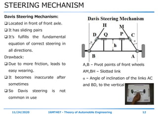
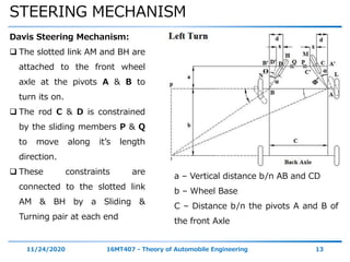
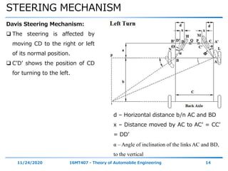
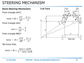
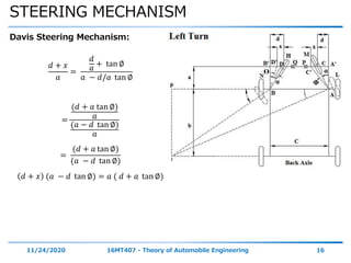
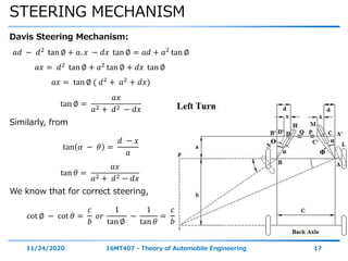
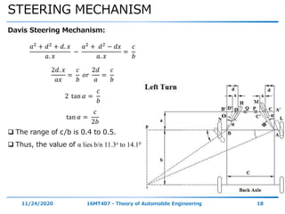
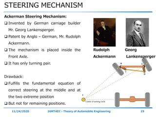
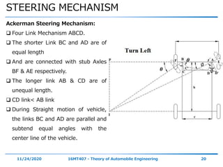
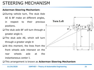
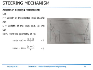
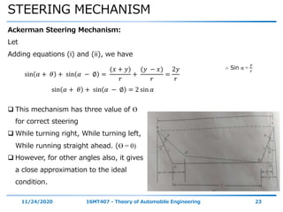
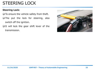
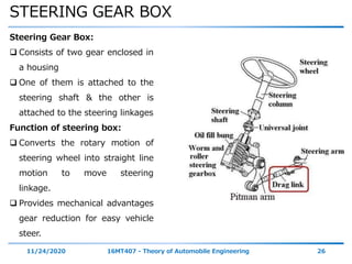
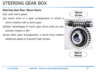
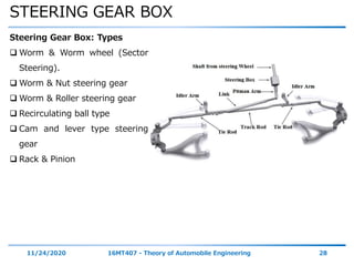
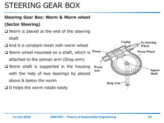
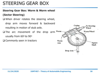
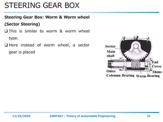
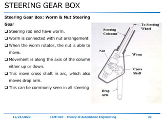
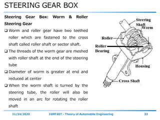
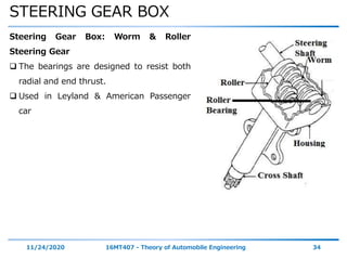
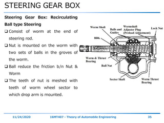
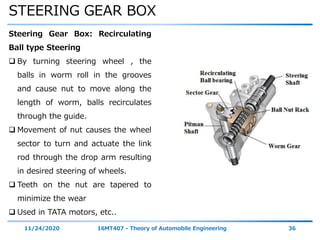
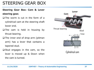
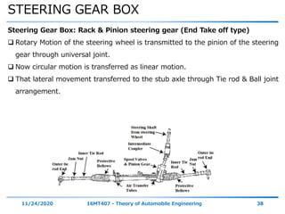
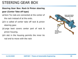
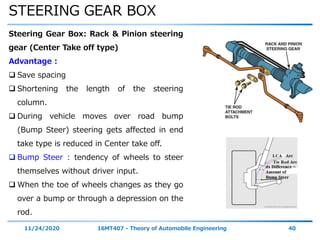
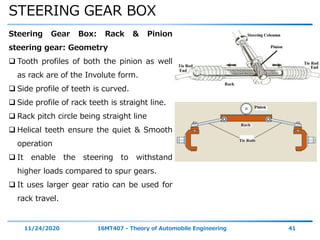
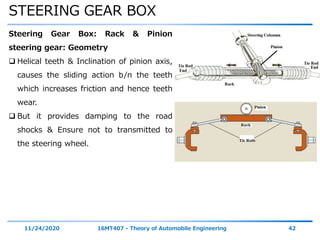
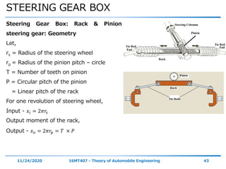
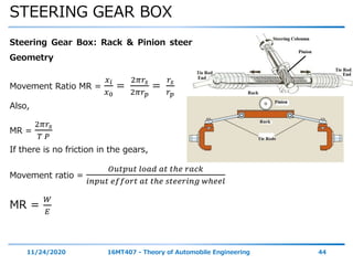
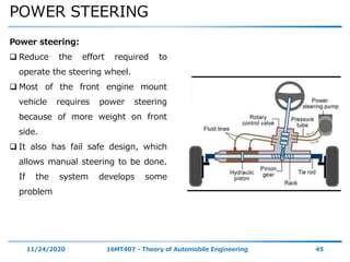
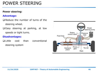
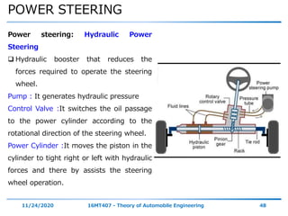
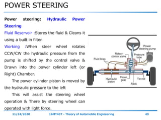
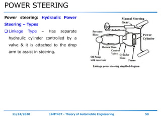
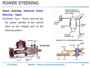
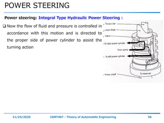
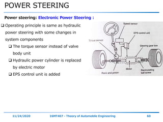
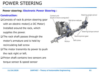
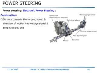
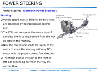
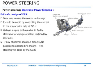
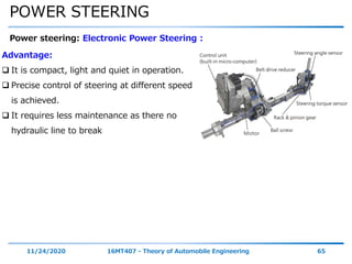
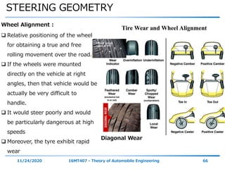
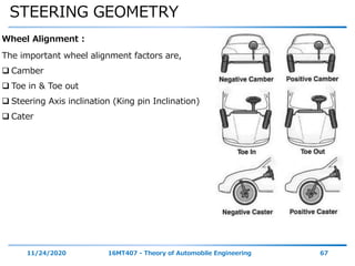
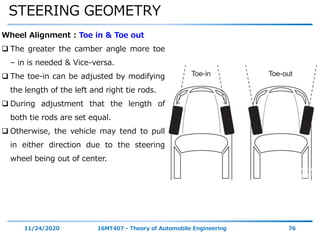
The document discusses vehicle steering systems. It begins with an introduction to basic steering components and principles. It then covers various topics related to steering mechanisms, including Davis and Ackerman steering mechanisms. It also discusses steering ratio, steering lock, steering gear boxes including different types, and power steering. The document provides information on key factors for proper steering such as steerability and stability.
This document discusses steering mechanisms for vehicles. It describes the condition for true rolling as having an instantaneous center where the front wheel axes meet the rear axis when turning. This requires the inner wheel to turn through a greater angle than the outer wheel. The main types of steering mechanisms are the Ackerman and Davis systems. The Ackerman mechanism is most widely used due to its simplicity and ability to achieve true rolling through an instantaneous center point between the wheel axes. It has turning pairs behind the wheels while the Davis mechanism has sliding pairs in front of the wheels and is more prone to wear.
2b9fc module iii steering system_ part-ii (2)Tanvi Gautam
The document discusses steering systems and components. It describes steering linkages used in vehicles with rigid axle front suspensions and independent front suspensions. It also discusses different types of steering gears like rack and pinion gears, and how power steering systems and electronic power steering systems work. It provides details on Davis steering mechanism and Ackerman steering mechanism.
The document provides an overview of automobiles and automobile power plants. It discusses the classification of automobiles based on use, capacity, make, fuel used, body style, wheels, drive, and transmission. The major components of an automobile including the frame, suspension, power plant, transmission system, electrical system, and control systems are described. Different automobile layouts such as front-engine rear-wheel drive, rear-engine rear-wheel drive, and front-engine front-wheel drive are summarized. Safety features in cars like seat belts, air bags, anti-lock brakes, and electronic stability control are highlighted. Different types of automobile power plants including internal combustion engines, electrical vehicles, fuel cells, and hybrid systems are
The document provides an overview of automotive transmission systems, including their main components and functions. It discusses the purpose of the transmission to transmit power from the engine to the driving wheels through a system of gears that allows for different speed and torque ratios. The key components covered are the clutch, gearbox, driveshaft, differential, and axle. Manual, automated manual, automatic, continuously variable, and dual-clutch transmissions are also summarized.
The document discusses various types of automobile suspension systems. It describes independent suspension systems that allow each wheel to move independently and non-independent systems where the wheels are attached to a solid axle. Common types of independent suspension include MacPherson strut suspension, wishbone suspension, and solid rear axle suspension. The document also covers suspension components like springs, shock absorbers, control arms, and sway bars. It provides advantages and disadvantages of different suspension types.
This document discusses vehicle suspension systems. It begins with an introduction to suspension systems, noting their purposes of connecting the vehicle body to wheels, absorbing shocks, and maintaining road contact. It then covers various suspension system types including rigid axle and independent suspensions. Specific suspension designs are described such as double wishbone, MacPherson strut, and air suspensions. Suspension movements and the role of springs and shock absorbers are also outlined.
Understeering and oversteering effects occur when taking a turn as the centrifugal force produces a side thrust on the vehicle. To sustain this force, the plane of the wheels must form an angle relative to the direction of motion. This angle is known as the slip or creep angle, which ranges from 8 to 10 degrees. It is the angle between the direction of motion and the center plane of the tire. The force produced due to the side thrust is called the cornering force. Understeering occurs when the front slip angle is greater than the rear, causing the vehicle to steer into the turn. Oversteering happens when the rear slip angle is larger, making the vehicle steer away from the turn.
This document provides an overview of steering systems for vehicles. It discusses the basic requirements and functions of a steering system, which include controlling the direction of vehicle wheels, providing stability while driving straight, and minimizing tire wear. It then describes the principles of Ackermann steering geometry and the conditions for proper steering. Finally, it outlines different types of steering mechanisms, focusing on rack and pinion steering gears, which convert the rotational motion of the steering wheel to linear motion at the wheels.
An axle is a central shaft that supports rotating wheels. On vehicles, the axle can be fixed to the wheels and rotate with them, or fixed to the vehicle with the wheels rotating around it. Bearings are provided where the axle is mounted. The document discusses different types of rear axles like full floating, semi floating, and three quarter floating axles. It also discusses front axles, describing them as either dead or live axles. Finally, it lists four types of stub axles used to connect front wheels to front axles: Elliot, reversed Elliot, Lamoine, and reversed Lamoine.
The document discusses vehicle frames, including their objectives, types, construction methods, and loads. It begins by outlining the session objectives of understanding frame material selection, loads on frames, and frame construction types. It then defines frames as the main chassis component that supports other parts. The key types discussed are conventional, semi-integral, and integral frames. Materials covered include steel alloys, with details on channel, box, tubular, and I-beam cross sections. Loads on frames from acceleration, braking, impacts and more are also summarized.
The document is a PowerPoint presentation on automobile engineering given by Assistant Professor Mahesh Kumar. It covers topics such as the basic concepts of automobile engineering, classifications of automobiles, transmission systems including clutches, gear ratios, driveshafts and differentials, and other systems like steering, brakes and suspension. The presentation provides an overview of key terms and components in automobile engineering.
The document discusses various components and types of steering gears used in automobiles. It describes common steering mechanisms like rack and pinion gears that convert rotational motion of the steering wheel into linear motion to turn the wheels. Power steering systems are also summarized, including hydraulic and electric power steering that apply pressure or torque to assist the driver in turning the wheels.
The document discusses various types of automotive braking systems. It describes the principles of hydraulic brakes, which use fluid pressure to provide equal braking force to all wheels according to Pascal's law. Drum brakes are also summarized, noting how brake shoes expand outward to contact the rotating drum and slow the wheels. Disc brakes are outlined as having pads that clamp onto a central disc attached to the wheel. Power brakes are mentioned as using engine vacuum pressure to boost braking force applied by the driver.
The document summarizes different types of car seats and mechanisms in vehicles. It discusses:
1. The types of car seats including rear facing, portable, forward facing, mobile, and convertible seats.
2. The evolution of driver seat design from the 19th century to modern times.
3. The construction and working of door lock, power lock, and manual window regulating mechanisms. This includes how locks and windows are operated through various components like actuators, racks, gears, and linkages.
4. The construction and working of seat adjusting mechanisms which allow the driver's seat to slide forward and back on fixed rails.
The document summarizes the key components of an automobile's electrical system. It discusses how the system originally only included ignition but grew to include batteries, generators/alternators, starters, lights, and accessories. It then focuses on the battery system, describing how lead-acid batteries provide high surge currents needed for starter motors. The ignition system uses a coil, points, capacitor and distributor to generate and distribute the spark. Modern systems replaced magnetos with battery-operated coils and use alternators instead of generators to charge the battery and power electrical components.
Study of transmission system of automobileNikhil Chavda
The document summarizes the transmission system of an automobile. It defines the transmission system as the mechanism that transmits power from the engine to the driving wheels. It has three main components - the clutch, gearbox, and propeller shaft. The transmission allows the engine to be disconnected from the wheels, connected smoothly, and drives the wheels at different speeds. It enables torque multiplication for starting and leverage variation between the engine and wheels. The document discusses different types of transmission systems including mechanical, hydraulic, electrical and automatic systems. It also explains the power flow in sliding mesh and constant mesh gearboxes.
The document discusses various components that connect the transmission to the drive wheels, including the propeller shaft, universal joints, constant velocity joints, and slip joints. It provides details on the construction and function of each component. The propeller shaft transmits power from the transmission to the rear differential. Universal joints and constant velocity joints allow the shaft to transmit power through varying angles, while slip joints allow adjustments to the shaft length during vehicle movement.
This document discusses steering gear mechanisms used in vehicles. It introduces the basic principles of steering mechanisms, including that the front wheels turn to change the vehicle's direction while the back wheels remain straight. It describes two common steering mechanisms: Ackermann steering uses linkages to ensure the inside and outside wheels follow different radius circles during a turn. Davis steering is also an exact mechanism but has more sliding components, increasing wear and reducing accuracy compared to Ackermann steering. The key difference between the mechanisms is that Ackermann steering is behind the front wheels while Davis is in front, and Ackermann uses turning pairs while Davis uses sliding pairs.
This document provides an overview of different braking systems used in vehicles. It discusses mechanical, air/pneumatic, hydraulic, drum, disk, vacuum, and magnetic braking systems. Mechanical brakes use linkages to transfer brake force, while air/pneumatic, hydraulic, and vacuum brakes use air, brake fluid, or vacuum pressure respectively to transmit brake force over longer distances or with higher force. Drum brakes use pads that press outward against a rotating drum, while disk brakes use calipers to squeeze pads against a disk. Magnetic brakes generate braking through magnetic fields without friction.
The document provides information about braking systems. It discusses the main functions of braking systems which are to stop the vehicle safely and control the vehicle when descending hills. It describes the two main types of braking system layouts - front/rear hydraulic split and diagonal split. It explains the components of braking systems including the brake pedal, master cylinder, brake lines, and discusses different types of braking systems such as mechanical, hydraulic, pneumatic, and discusses components like brake linings. It provides diagrams to illustrate hydraulic and mechanical braking systems.
Drive shafts come in one-piece and two-piece designs, with two-piece used for longer wheelbases and including a center support bearing. Universal joints attach drive shafts to the transmission slip yoke end and rear axle flange end. Constant velocity joints in front-wheel drive vehicles and independent rear suspension vehicles allow for angular velocity differences between the drive shaft and the driven parts. Transfer cases are used on 4-wheel drive vehicles to connect both drive shafts together and can include part-time locking hubs to engage the front wheels through vacuum or electrically-powered solenoids.
The document discusses the requirements of a good steering system, including that it should be accurate, easy to handle, and require minimal effort. It also covers various aspects of wheel alignment such as camber angle, caster angle, toe-in/toe-out, and scrub radius that impact tire wear and vehicle stability. Proper wheel alignment reduces tire wear, improves gas mileage and safety, and prevents pulling to one side.
This document discusses a 4 wheel steering system. It provides an introduction and overview of the system, describing the different types including mechanical, hydraulic, and electro-hydraulic systems. It explains the working principles, functions, advantages, and applications of 4 wheel steering. In conclusion, it states that 4 wheel steering provides advantages over 2 wheel steering but the system is also more complex and expensive.
This document provides information on various types of transfer cases and differentials used in 4WD and AWD vehicles. It discusses how transfer cases are used to distribute torque to the front and rear axles. Integral transfer gears and part-time 4WD systems are described. Limited slip and locking differentials are also summarized, which help provide traction when one wheel loses grip.
The propeller shaft transmits power from the gearbox to the rear differential. It includes U-joints and a slip joint to adjust for length changes over bumps. There are two main types of propeller shaft: the torque tube type, which fully encloses the shaft in a hollow tube connected to the rear axle housing, and the Hotchkiss type, which absorbs torque through the rear leaf spring using a shaft with universal joints and a sliding joint. Propeller shafts must be dynamically balanced, made of hardened steel to withstand torque loads, and designed to avoid resonance at high speeds.
This document discusses the history and components of automobile steering systems. It describes how early steering systems worked by pulling horse reins to turn buggy wheels. Later, systems were developed using linkages to connect the steering wheel to front wheels. Modern systems use power steering assisted by hydraulic or electric motors. Key components include the steering wheel, column, gear, rack and pinion, and linkages connecting to front knuckles to enable turning. Power steering greatly reduces steering effort for drivers.
The document discusses various axle systems used in vehicles. It describes the construction and function of rear axles, front axles, and stub axles. Rear axles are mounted at the rear of the vehicle and use axle shafts to transmit power from the differential to the rear wheels. Front axles provide steering action and support the front of the vehicle. Stub axles connect the wheels to the front and rear axles. The document outlines different types of rear axles including semi-floating, full-floating, and three-quarter floating designs.
The document discusses vehicle braking systems. It begins with session objectives on understanding proper braking system selection, braking material selection for efficiency, and the role of electronics in ABS and traction control systems. It then covers topics like introduction, brake classification, ABS, and traction control systems. The introduction section defines brakes and their functions, and discusses braking principles, factors like pressure, friction, surface area, geometry. It also covers braking force calculation, weight transfer during braking, and stopping distance calculation. Drum and disc brake components and types are described. [END SUMMARY]
This document describes a project report on a four wheel steering system submitted by four students to fulfill the requirements of a bachelor's degree in mechanical engineering. It includes an introduction to four wheel steering systems, the principles and concepts of how such a system works including rack and pinion arrangements and bevel gear transmissions to steer the rear wheels. It also provides background on steering geometry, ratios and turning radii and reviews literature on four wheel steering system modes for different speeds.
Design, Analysis and Simulation of Double Wishbone Suspension System for Form...IRJET Journal
This document describes the design, analysis, and simulation of a double wishbone suspension system for a formula student racing vehicle. The authors first discuss the basic parameters and requirements for the suspension system. They then describe the detailed design of the knuckle, wishbones, and helical coil spring. Finite element analysis is conducted on these components using ANSYS to analyze stresses and deformations. Finally, dynamic simulation of the full suspension system is performed using ADAMS software to analyze how kinematic parameters like camber angle and roll steer change with wheel travel. The results of the simulation match the designed parameters and help validate the suspension system design.
Design and Development of Linkage based Four Wheel Steering Mechanism for Veh...IRJET Journal
1) The document describes the design and development of a four wheel steering mechanism for vehicles to improve maneuverability.
2) A linkage-based design is proposed to connect the rear wheels to the steering column to enable turning of the rear wheels. This reduces the vehicle's turning radius.
3) Test results showed the turning radius was reduced from 4.4 meters to 2.8 meters using the four wheel steering system compared to conventional two wheel steering.
IRJET - A Review on Design and Assembly of Go- Kart Steering SystemIRJET Journal
This document provides a review of go-kart steering system design and assembly. It discusses the requirements of an effective steering system, including accuracy, minimal effort, and directional stability. The most common steering system used is the rack and pinion system, which is described in detail. Ackermann steering geometry is also covered, which ensures the inner and outer wheels trace circles of different radii during a turn to avoid skidding. Finite element analysis can be used to analyze steering components and determine stresses, loads, and deformations to evaluate safety. The goal of the paper is to provide an overview of go-kart steering mechanisms and considerations for design and optimization.
The document describes the fabrication of a four wheel steering system for a Maruti 800 vehicle. Key points:
- The rear wheels were modified to allow for steering capability by adding a second rack and pinion steering gearbox connected to the original front gearbox via transfer rods and bevel gears.
- In rear steer mode at low speeds, the rear wheels turn in the opposite direction of the front wheels, greatly reducing the turning radius.
- Benefits of the four wheel steering system include improved vehicle handling, stability, and reduced driver fatigue over long drives due to the easier steering capability.
- The successful implementation of the system allows for increased maneuverability and stability of vehicles.
This project report describes a 90 degree steering mechanism. It discusses the working of the mechanism which uses 4 DC motors, with two motors coupled to the front wheels and two to the rear wheels. Additional motors are connected via chain drives to rotate the wheels 90 degrees, allowing the vehicle to park perpendicular to the street. The report lists the various parts used including the chassis board, L-clamps, DC motors, fiber wheels, mild steel frame, nuts, bolts and more. It provides the specifications and purpose of each part. The mechanism is aimed to make parallel parking easier.
The document discusses the need for gear boxes in vehicles. It describes the various resistances that act on a moving vehicle, such as rolling resistance from friction between the tires and road, wind resistance which increases with speed, and gradient resistance from road inclines. A gear box is necessary because the engine's torque varies with speed but vehicles must be able to maintain motion over varying resistances and road conditions. By changing gears, the transmission can better match the engine's output to the demands placed on the driving wheels.
Design and Optimization of Double Wishbone Suspension System for ATVsIRJET Journal
This document discusses the design and optimization of a double wishbone suspension system for all-terrain vehicles (ATVs). It aims to minimize weight and cost while improving performance. CAD software was used to model the geometry, which was then simulated in ADAMS and analyzed in ANSYS for stress and deformation. The optimized design improved suspension parameters like camber angle, caster angle, king pin inclination and scrub radius. It also reduced roll steer compared to the original design. The optimized double wishbone suspension is suitable for installing on ATVs as well as other vehicles.
The document discusses various aspects of steering systems, including:
1. The primary and secondary functions of steering systems which allow the driver to control vehicle direction and provide stability and feedback.
2. Common causes of stiff steering like insufficient lubrication or incorrect tire pressure and alignment.
3. Requirements of a good steering system including accuracy, ease of handling, and minimal effort.
4. Types of front axles including live and dead axles and their characteristics.
This document discusses steering, braking, and suspension systems for vehicles. It covers topics like steering geometry, types of steering gear boxes, power steering, types of front axles, suspension systems, braking systems, anti-lock braking systems, and traction control systems. The document provides details on steering geometry components like camber, caster, kingpin inclination, toe-in/toe-out, and their purposes. It also describes common steering gear boxes like worm and wheel, worm and sector, rack and pinion, and their operating mechanisms.
The document provides an answer key for a mechanical engineering exam on automobile engineering. It includes multiple choice questions on topics like axle failures, universal joints, overdrive systems, and steering principles. It also includes longer answer questions on components like clutches, gearboxes, differentials, and rear axle designs. The last section defines important steering geometry terms that describe the angular relationship between suspension parts and how it affects vehicle handling.
IRJET- Design and Fabrication of an All-Terrain VehicleIRJET Journal
1. Students at IES College of Engineering designed and fabricated an all-terrain vehicle from a two-wheeler.
2. The design considerations included transforming the two-wheeler into a four-wheeler while maintaining stability at slower speeds. An independent suspension system was used for the front wheels and a mono-shock suspension for the rear.
3. Tests of the vehicle showed that the design satisfied the requirements for off-road use. The vehicle was able to propagate over almost all terrains as intended.
International Journal of Computational Engineering Research(IJCER) is an intentional online Journal in English monthly publishing journal. This Journal publish original research work that contributes significantly to further the scientific knowledge in engineering and Technology.
Baja project 2010 report by bangalore institue of techKapil Singh
This document provides a summary of the final design report for Team Stratos' mini-Baja vehicle that will compete in Baja SAEASIA 2010. The team divided responsibilities for major subsystems and used CAD modeling, FEA analysis, and dynamics simulations to optimize the design. Key aspects of the vehicle design include a roll cage frame made of steel that was analyzed for impact, torsion, and rollover testing. A double wishbone suspension and disc brakes were chosen. Ergonomic features like an adjustable seat and tilt steering were included for safety. Performance estimates indicate a 0-60 time of 7 seconds and a braking distance of 2.89 meters.
Geometrical Analysis and Design of Tension-Actuated Ackermann Steering System...Scientific Review SR
The tension-actuated steering system is a vehicular steering design that comprises a motorized gear system, pulleys, inelastic string, main steering bar, and a strain gauge. This development is aimed to produce a steering design that could enhance the efficiency of steering systems in quad-wheeled (i.e. four-wheeled) robots. In this work, the steering system of conventional passenger vehicles and existing quad-wheeled robots are reviewed and their technical deficiencies are improved based on cost, power and production factors. Thus, the tension-actuated steering system is proposed as a solution for mechanizing steering functions in quad-wheeled robots. It is expected that this work will stimulate interest and enthusiasm.
Single Speed Transmission for Electric VehiclesSameer Shah
This document summarizes Sameer Shah's seminar report on designing a single speed transmission for electric vehicles. The report describes the design process for a helical gear transmission with a gear ratio of 12.25:1 to meet the torque requirements of an electric vehicle. Structural simulation was performed on the gears to validate they could withstand the expected loads. The gears would be manufactured using hobbing or shaping and finished through grinding or honing. Lubrication would be provided by Omega 690 gear oil for its low temperature fluidity and high temperature strength.
IRJET- Design & Manufacturing of Double Wishbone Suspension and Wheel Ass...IRJET Journal
This document describes the design and manufacturing of a double wishbone suspension system and wheel assembly for a formula-style electric vehicle. It discusses the objectives to withstand high-speed cornering over bumps. The methodology includes designing the components in CATIA and SolidWorks, analyzing them in ANSYS and simulating the suspension system in MSC ADAMS. The key components designed are the wishbones, upright, hub, and spring. Materials are selected based on objectives like strength and weight. Static analysis of the wheel assembly and simulation of the suspension kinematics are presented. The manufacturing process of the wishbones by cutting, grinding, fitting and welding is also outlined.
The document discusses unmanned aerial vehicles (UAVs), including:
1) The objectives of the session are to understand the introduction, types, elements, missions, and navigation systems of UAVs.
2) UAVs consist of an air vehicle, ground control station, data link, and may have payloads like cameras. They come in various sizes and can perform missions like reconnaissance and surveillance.
3) UAV navigation systems include GPS, inertial navigation, and they may use waypoint navigation to follow a planned route.
The document discusses the benefits of exercise for mental health. Regular physical activity can help reduce anxiety and depression and improve mood and cognitive functioning. Exercise causes chemical changes in the brain that may help protect against mental illness and improve symptoms.
The document discusses alternative fuels to fossil fuels, focusing on methanol and ethanol. It provides details on:
- The production processes of methanol and ethanol, involving synthesis from other chemicals or fermentation of biomass respectively.
- The properties and modifications needed to engines to enable their use, such as increasing compression ratios, jet sizes, and pump capacities to accommodate their combustion characteristics and higher octane ratings.
- The benefits of these alternative fuels include lower emissions than gasoline and the renewable nature of ethanol.
The document discusses the vehicle body construction. It begins by introducing the objectives of the session which are to understand how vehicle parts form the body and give an aesthetic view to consumers. It then covers various topics related to vehicle body design including the importance of design, types of bodies, body construction components, body materials, and aerodynamics. The document focuses on the components that make up the vehicle body, how the body is constructed, and the purpose of key parts like doors, hood, seats, and other interior and exterior parts.
The document discusses turbochargers, including:
- A turbocharger uses the waste heat from exhaust gases to power a turbine, which spins a compressor to force more air into the engine cylinders, increasing power.
- It has a turbine section, compressor section, bearing housing, and wastegate valve. The bearing allows the turbine and compressor wheels to spin at high speeds while absorbing vibrations. The wastegate diverts some exhaust to control boost pressure.
- During acceleration, more exhaust flow spins the turbine and compressor faster, supplying more air/fuel to the engine for more power. The wastegate manages boost pressure to prevent damage from excessive pressure rises.
The document discusses catalytic converters, which are emission control devices that convert toxic gases from vehicle exhaust into less toxic pollutants. It describes the functions of catalytic converters, their construction using a ceramic core with precious metal catalysts, and how they work to oxidize carbon monoxide and hydrocarbons while also reducing oxides of nitrogen through redox reactions. The document differentiates between two-way catalytic converters, which control carbon monoxide and hydrocarbons, and three-way catalytic converters, which also control oxides of nitrogen emissions. Three-way catalytic converters are highlighted as the most effective at reducing the three main pollutants from vehicle exhaust.
The function of an Electronic ignition system is to produce the spark to ignite the air-fuel mixture in a timely manner for maintaining the effective combustion
The document discusses various electronic fuel injection systems for compression ignition (CI) engines. It begins by explaining the principles of CI engines and how they rely on high temperatures from compression to ignite fuel rather than a spark plug. It then categorizes CI engine injection systems as using either compressed air or high-pressure liquid fuel directly. Various common electronic systems are described in detail, including individual pump systems, common rail, and unit injector systems. The document focuses on explaining the working of the modern common rail system, describing its components and fuel injection process.
Welcome to ASP Cranes, your trusted partner for crane solutions in Raipur, Chhattisgarh! With years of experience and a commitment to excellence, we offer a comprehensive range of crane services tailored to meet your lifting and material handling needs.
At ASP Cranes, we understand the importance of reliable and efficient crane operations in various industries, from construction and manufacturing to logistics and infrastructure development. That's why we strive to deliver top-notch solutions that enhance productivity, safety, and cost-effectiveness for our clients.
Our services include:
Crane Rental: Whether you need a crawler crane for heavy lifting or a hydraulic crane for versatile operations, we have a diverse fleet of well-maintained cranes available for rent. Our rental options are flexible and can be customized to suit your project requirements.
Crane Sales: Looking to invest in a crane for your business? We offer a wide selection of new and used cranes from leading manufacturers, ensuring you find the perfect equipment to match your needs and budget.
Crane Maintenance and Repair: To ensure optimal performance and safety, regular maintenance and timely repairs are essential for cranes. Our team of skilled technicians provides comprehensive maintenance and repair services to keep your equipment running smoothly and minimize downtime.
Crane Operator Training: Proper training is crucial for safe and efficient crane operation. We offer specialized training programs conducted by certified instructors to equip operators with the skills and knowledge they need to handle cranes effectively.
Custom Solutions: We understand that every project is unique, which is why we offer custom crane solutions tailored to your specific requirements. Whether you need modifications, attachments, or specialized equipment, we can design and implement solutions that meet your needs.
At ASP Cranes, customer satisfaction is our top priority. We are dedicated to delivering reliable, cost-effective, and innovative crane solutions that exceed expectations. Contact us today to learn more about our services and how we can support your project in Raipur, Chhattisgarh, and beyond. Let ASP Cranes be your trusted partner for all your crane needs!
Ever been troubled by the blinking sign and didn’t know what to do?
Here’s a handy guide to dashboard symbols so that you’ll never be confused again!
Save them for later and save the trouble!
Expanding Access to Affordable At-Home EV Charging by Vanessa WarheitForth
Vanessa Warheit, Co-Founder of EV Charging for All, gave this presentation at the Forth Addressing The Challenges of Charging at Multi-Family Housing webinar on June 11, 2024.
Understanding Catalytic Converter Theft:
What is a Catalytic Converter?: Learn about the function of catalytic converters in vehicles and why they are targeted by thieves.
Why are They Stolen?: Discover the valuable metals inside catalytic converters (such as platinum, palladium, and rhodium) that make them attractive to criminals.
Steps to Prevent Catalytic Converter Theft:
Parking Strategies: Tips on where and how to park your vehicle to reduce the risk of theft, such as parking in well-lit areas or secure garages.
Protective Devices: Overview of various anti-theft devices available, including catalytic converter locks, shields, and alarms.
Etching and Marking: The benefits of etching your vehicle’s VIN on the catalytic converter or using a catalytic converter marking kit to make it traceable and less appealing to thieves.
Surveillance and Monitoring: Recommendations for using security cameras and motion-sensor lights to deter thieves.
Statistics and Insights:
Theft Rates by Borough: Analysis of data to determine which borough in NYC experiences the highest rate of catalytic converter thefts.
Recent Trends: Current trends and patterns in catalytic converter thefts to help you stay aware of emerging hotspots and tactics used by thieves.
Benefits of This Presentation:
Awareness: Increase your awareness about catalytic converter theft and its impact on vehicle owners.
Practical Tips: Gain actionable insights and tips to effectively prevent catalytic converter theft.
Local Insights: Understand the specific risks in different NYC boroughs, helping you take targeted preventive measures.
This presentation aims to equip you with the knowledge and tools needed to protect your vehicle from catalytic converter theft, ensuring you are prepared and proactive in safeguarding your property.
What Could Be Behind Your Mercedes Sprinter's Power Loss on Uphill RoadsSprinter Gurus
Unlock the secrets behind your Mercedes Sprinter's uphill power loss with our comprehensive presentation. From fuel filter blockages to turbocharger troubles, we uncover the culprits and empower you to reclaim your vehicle's peak performance. Conquer every ascent with confidence and ensure a thrilling journey every time.
Implementing ELDs or Electronic Logging Devices is slowly but surely becoming the norm in fleet management. Why? Well, integrating ELDs and associated connected vehicle solutions like fleet tracking devices lets businesses and their in-house fleet managers reap several benefits. Check out the post below to learn more.
EV Charging at MFH Properties by Whitaker JamiesonForth
Whitaker Jamieson, Senior Specialist at Forth, gave this presentation at the Forth Addressing The Challenges of Charging at Multi-Family Housing webinar on June 11, 2024.
1. SRI KRISHNA COLLEGE OF ENGINEERING AND TECHNOLOGY
DEPARTMENT OF MECHATRONICS ENGINEERING
Session: Vehicle Steering System
11/24/2020 16MT407 - Theory of Automobile Engineering 1
MODULE 1
2. SESSION OBJECTIVES
11/24/2020 16MT407 - Theory of Automobile Engineering 2
On the completion of this session, the students might
be able to understand,
Proper selection of steering mechanism for vehicle
Good chosen of steering gear box for easy steering
Important of wheel alignment factors for good
Steerability & stability of vehicle.
3. Topics
Introduction
Steering Mechanism
Steering Ratio
Steering Lock
Steering Gear Box
Power Steering
Steering Geometry
11/24/2020 16MT407 - Theory of Automobile Engineering 3
4. Introduction
11/24/2020 16MT407 - Theory of Automobile Engineering 4
Simple steering system:
Change the direction of motion of a
vehicle.
Simply converted the Rotary motion
of steering wheel into angular turn
of front wheels.
The motion of steering shaft is
transferred to the steering gear
box.
Gear box convert the rotary motion
into lateral motion
And it will transferred it to steering
linkage. Components of steering system
5. Introduction
11/24/2020 16MT407 - Theory of Automobile Engineering 5
Simple steering system:
The left & Right linkages are
connected to the steering knuckle
on the left & right wheels
respectively.
Each knuckle is pivoted on the
suspension’s upper & lower arms
and rotate about the axis.
This cause the wheel to move left
or right, allowing the direction of
the vehicle to be changed.
Components of steering system
6. Introduction
11/24/2020 16MT407 - Theory of Automobile Engineering 6
Important terms used in Steering:
Steerability:
Measure of the vehicle’s
responsiveness to the steering
operation of the driver.
Stability:
Dynamic Meaning of vehicle
Capability of a vehicle to restore
original motion by itself without
intervention of driver.
When there is some external
disturbance during steady driving.
7. Introduction
11/24/2020 16MT407 - Theory of Automobile Engineering 7
Principle of Correct Steering:
When the vehicle take a turn,
the front wheel along with the
respective axles turn about
the respected pivot points
The rear wheel remains
straight and do not turn.
The steering is done by means
of front wheels.
8. Introduction
11/24/2020 16MT407 - Theory of Automobile Engineering 8
Principle of Correct Steering:
For avoid skidding, the two
front wheels must turn about
the same instantaneous center
I,
Which lies on the axis of the
back wheels
If “I” for two front wheels do
not coincide with the “I” of the
rear wheels, skidding of the
front wheel takes place
This will leads to more wear &
tear of the tyres
9. Introduction
11/24/2020 16MT407 - Theory of Automobile Engineering 9
Principle of Correct Steering:
Let,
a = Wheel Track
B = Wheel Base
C = Distance b/n the pivot
points of wheel
From Triangle IBP,
cot 𝜃 =
𝐵𝑃
𝐼𝑃
From Triangle IAP,
cot ∅ =
𝐴𝑃
𝐼𝑃
=
𝐴𝐵 + 𝐵𝑃
𝐼𝑃
=
𝐴𝐵
𝐼𝑃
+
𝐵𝑃
𝐼𝑃
=
𝑐
𝑏
+ cot 𝜃
B A
C D
10. Introduction
11/24/2020 16MT407 - Theory of Automobile Engineering 10
Principle of Correct Steering:
cot ∅ − cot 𝜃 =
𝑐
𝑏
This is the fundamental equation
of correct steering, If this
condition is satisfied, then there
will be no skidding of the wheels,
when the wheel take a turn.
B A
C D
11. STEERING MECHANISM
11/24/2020 16MT407 - Theory of Automobile Engineering 11
Steering Mechanism:
Good turning means, all the
four wheels must rotate about
the common “I”.
In order to achieve this two
types of mechanism is
followed by automakers.
Davis Steering Mechanism
Ackerman Steering
Mechanism
12. STEERING MECHANISM
11/24/2020 16MT407 - Theory of Automobile Engineering 12
Davis Steering Mechanism:
Located in front of front axle.
It has sliding pairs
It’s fulfills the fundamental
equation of correct steering in
all directions.
Drawback:
Due to more friction, leads to
easy wearing.
It becomes inaccurate after
sometimes
So Davis steering is not
common in use
A,B – Pivot points of front wheels
AM,BH – Slotted link
α – Angle of inclination of the links AC
and BD, to the vertical
α α
13. STEERING MECHANISM
11/24/2020 16MT407 - Theory of Automobile Engineering 13
Davis Steering Mechanism:
The slotted link AM and BH are
attached to the front wheel
axle at the pivots A & B to
turn its on.
The rod C & D is constrained
by the sliding members P & Q
to move along it’s length
direction.
These constraints are
connected to the slotted link
AM & BH by a Sliding &
Turning pair at each end
α
αϴ
Φ
a – Vertical distance b/n AB and CD
b – Wheel Base
C – Distance b/n the pivots A and B of
the front Axle
14. STEERING MECHANISM
11/24/2020 16MT407 - Theory of Automobile Engineering 14
Davis Steering Mechanism:
The steering is affected by
moving CD to the right or left
of its normal position.
C’D’ shows the position of CD
for turning to the left.
α
αϴ
Φ
d – Horizontal distance b/n AC and BD
x – Distance moved by AC to AC’ = CC’
= DD’
α – Angle of inclination of the links AC and BD,
to the vertical
15. STEERING MECHANISM
11/24/2020 16MT407 - Theory of Automobile Engineering 15
Davis Steering Mechanism:
From triangle AA’C’,
tan(𝛼 + ∅) =
𝐴′ 𝐶′
𝐴𝐴′
=
𝑑 + 𝑥
𝑎
From triangle AA’C
tan 𝛼 =
𝐴′
𝐶
𝐴𝐴′
=
𝑑
𝑎
From triangle BB’D’
tan 𝛼 − 𝜃 =
𝐵′
𝐷′
𝐵𝐵′
=
𝑑 − 𝑥
𝑎
We know that,
tan 𝛼 + ∅ =
tan 𝛼 + tan ∅
1 − tan 𝛼 . tan ∅
α
αϴ
Φ
16. STEERING MECHANISM
11/24/2020 16MT407 - Theory of Automobile Engineering 16
Davis Steering Mechanism:
𝑑 + 𝑥
𝑎
=
𝑑
𝑎
+ tan ∅
𝑎 − 𝑑/𝑎 tan ∅
=
(𝑑 + 𝑎 tan ∅)
𝑎
(𝑎 − 𝑑 tan ∅)
𝑎
=
(𝑑 + 𝑎 tan ∅)
(𝑎 − 𝑑 tan ∅)
𝑑 + 𝑥 (𝑎 − 𝑑 tan ∅) = 𝑎 ( 𝑑 + 𝑎 tan ∅)
α
αϴ
Φ
17. STEERING MECHANISM
11/24/2020 16MT407 - Theory of Automobile Engineering 17
Davis Steering Mechanism:
𝑎𝑑 − 𝑑2
tan ∅ + 𝑎. 𝑥 − 𝑑𝑥 tan ∅ = 𝑎𝑑 + 𝑎2
tan ∅
𝑎𝑥 = 𝑑2 tan ∅ + 𝑎2 tan ∅ + 𝑑𝑥 tan ∅
𝑎𝑥 = tan ∅ ( 𝑑2
+ 𝑎2
+ 𝑑𝑥)
tan ∅ =
𝑎𝑥
𝑎2 + 𝑑2 − 𝑑𝑥
Similarly, from
tan 𝛼 − 𝜃 =
𝑑 − 𝑥
𝑎
tan 𝜃 =
𝑎𝑥
𝑎2 + 𝑑2 − 𝑑𝑥
We know that for correct steering,
cot ∅ − cot 𝜃 =
𝑐
𝑏
𝑜𝑟
1
tan ∅
−
1
tan 𝜃
=
𝑐
𝑏
α
αϴ
Φ
18. STEERING MECHANISM
11/24/2020 16MT407 - Theory of Automobile Engineering 18
Davis Steering Mechanism:
𝑎2 + 𝑑2 + 𝑑. 𝑥
𝑎. 𝑥
−
𝑎2 + 𝑑2 − 𝑑𝑥
𝑎. 𝑥
=
𝑐
𝑏
2𝑑. 𝑥
𝑎𝑥
=
𝑐
𝑏
𝑜𝑟
2𝑑
𝑎
=
𝑐
𝑏
2 tan 𝛼 =
𝑐
𝑏
tan 𝛼 =
𝑐
2𝑏
The range of c/b is 0.4 to 0.5.
Thus, the value of α lies b/n 11.3o to 14.10
α
αϴ
Φ
19. STEERING MECHANISM
11/24/2020 16MT407 - Theory of Automobile Engineering 19
Ackerman Steering Mechanism:
Invented by German carriage builder
Mr. Georg Lankensperger.
Patent by Anglo – German, Mr. Rudolph
Ackermann.
The mechanism is placed inside the
Front Axle.
It has only turning pair.
Drawback:
Fulfills the fundamental equation of
correct steering at the middle and at
the two extreme position
But not for remaining positions.
Georg
Lankensperger
Rudolph
Ackermann
20. STEERING MECHANISM
11/24/2020 16MT407 - Theory of Automobile Engineering 20
Ackerman Steering Mechanism:
Four Link Mechanism ABCD.
The shorter Link BC and AD are of
equal length
And are connected with stub Axles
BF & AE respectively.
The longer link AB & CD are of
unequal length.
CD link< AB link
During Straight motion of vehicle,
the links BC and AD are parallel and
subtend equal angles with the
center line of the vehicle.
𝜽
𝜽
∅
∅
21. STEERING MECHANISM
11/24/2020 16MT407 - Theory of Automobile Engineering 21
Ackerman Steering Mechanism:
During vehicle turn, The stub Axle
AE & BF make an different angles,
in respect to their previous
positions.
The stub axle BF will turn through a
greater angle ϴ,
The stub axle AE, which will turn
through a greater angle Ф
At this moment, the lines from the
front wheels axle intersect on the
rear wheels axle at the
instantaneous center I.
𝜽
𝜽
∅
∅
This arrangement is known as Ackerman Steering Mechanism
22. STEERING MECHANISM
11/24/2020 16MT407 - Theory of Automobile Engineering 22
Ackerman Steering Mechanism:
Let
r = Length of the shorter links BC and
AD
L = Length of the track rod, i.e link
CD
Now, from the geometry of fig,
sin ∝ + 𝜃 =
(𝑥 + 𝑦)
𝑟
sin 𝛼 − ∅ =
(𝑦 − 𝑥)
𝑟
- i
- ii
23. STEERING MECHANISM
11/24/2020 16MT407 - Theory of Automobile Engineering 23
Ackerman Steering Mechanism:
Let
Adding equations (i) and (ii), we have
sin 𝛼 + 𝜃 + sin 𝛼 − ∅ =
(𝑥 + 𝑦)
𝑟
+
(𝑦 − 𝑥)
𝑟
=
2𝑦
𝑟
sin 𝛼 + 𝜃 + sin 𝛼 − ∅ = 2 sin 𝛼
∴ Sin α =
𝑦
𝑟
This mechanism has three value of ϴ
for correct steering
While turning right, While turning left,
While running straight ahead. (ϴ = 0)
However, for other angles also, it gives
a close approximation to the ideal
condition.
24. STEERING RATIO
11/24/2020 16MT407 - Theory of Automobile Engineering 24
Steering Gear Ratio:
Ratio of angle turned by the steering wheel to the corresponding angles of
stub axle (Steering Knuckle or front wheels)
Now a days, for cars steering gear ratio 12:1, for heavy vehicles 35:1,
Larger steering gear ratio will reduce the amount of steering effort required
But the steering wheel needs to be turned through a larger angle.
It says steering will not very responsive.
On the other hand smaller steering ratio will improve the steering response.
But increasing the steering effort
25. STEERING LOCK
11/24/2020 16MT407 - Theory of Automobile Engineering 25
Steering Lock:
To ensure the vehicle safety from theft.
The put the lock for steering, also
switch off the ignition.
It will lock the gear shift lever of the
transmission.
26. STEERING GEAR BOX
11/24/2020 16MT407 - Theory of Automobile Engineering 26
Steering Gear Box:
Consists of two gear enclosed in
a housing
One of them is attached to the
steering shaft & the other is
attached to the steering linkages
Function of steering box:
Converts the rotary motion of
steering wheel into straight line
motion to move steering
linkage.
Provides mechanical advantages
gear reduction for easy vehicle
steer.
27. STEERING GEAR BOX
11/24/2020 16MT407 - Theory of Automobile Engineering 27
Steering Gear Box: Worm Gears
It used worm gears
A worm drive is a gear arrangement in which a
worm meshes with a worm gear
Major advantages of worm gear drive units are can
transfer motion in 90o
Like other gear arrangement, a worm drive reduce
rotational speed or transmit high torque.
Worm
Screw
Worm
Wheel
28. STEERING GEAR BOX
11/24/2020 16MT407 - Theory of Automobile Engineering 28
Steering Gear Box: Types
Worm & Worm wheel (Sector
Steering).
Worm & Nut steering gear
Worm & Roller steering gear
Recirculating ball type
Cam and lever type steering
gear
Rack & Pinion
29. STEERING GEAR BOX
11/24/2020 16MT407 - Theory of Automobile Engineering 29
Steering Gear Box: Worm & Worm wheel
(Sector Steering)
Worm is placed at the end of the steering
shaft
And it is constant mesh with worm wheel
Worm wheel mounted on a shaft, which is
attached to the pitman arm (Drop arm)
Worm shaft is supported in the housing
with the help of two bearings by placed
above & below the worm
It helps the worm rotate easily
30. STEERING GEAR BOX
11/24/2020 16MT407 - Theory of Automobile Engineering 30
Steering Gear Box: Worm & Worm wheel
(Sector Steering)
When driver rotates the steering wheel,
drop arm moves forward & backward
resulting in motion of stub axle.
The arc movement of the drop arm
usually from 60o to 90o
Commonly seen in tractors
31. STEERING GEAR BOX
11/24/2020 16MT407 - Theory of Automobile Engineering 31
Steering Gear Box: Worm & Worm wheel
(Sector Steering)
This is similar to worm & worm wheel
type.
Here instead of worm wheel, a sector
gear is placed
32. STEERING GEAR BOX
11/24/2020 16MT407 - Theory of Automobile Engineering 32
Steering Gear Box: Worm & Nut Steering
Gear
Steering rod end have worm.
Worm is connected with nut arrangement
When the worm rotates, the nut is able to
move.
Movement is along the axis of the column
either up or down.
This move cross shaft in arc, which also
moves drop arm.
This can be commonly seen in all steering
33. STEERING GEAR BOX
11/24/2020 16MT407 - Theory of Automobile Engineering 33
Steering Gear Box: Worm & Roller
Steering Gear
Worm and roller gear have two teethed
roller which are fastened to the cross
shaft called roller shaft or sector shaft.
The threads of the worm gear are meshed
with roller shaft at the end of the steering
tube
Diameter of worm is greater at end and
reduced at center
When the worm shaft is turned by the
steering tube, the roller will also be
moved in an arc for rotating the roller
shaft
34. STEERING GEAR BOX
11/24/2020 16MT407 - Theory of Automobile Engineering 34
Steering Gear Box: Worm & Roller
Steering Gear
The bearings are designed to resist both
radial and end thrust.
Used in Leyland & American Passenger
car
35. STEERING GEAR BOX
11/24/2020 16MT407 - Theory of Automobile Engineering 35
Steering Gear Box: Recirculating
Ball type Steering
Consist of worm at the end of
steering rod.
Nut is mounted on the worm with
two sets of balls in the groves of
the worm.
Ball reduce the friction b/n Nut &
Worm
The teeth of nut is meshed with
teeth of worm wheel sector to
which drop arm is mounted.
36. STEERING GEAR BOX
11/24/2020 16MT407 - Theory of Automobile Engineering 36
Steering Gear Box: Recirculating
Ball type Steering
By turning steering wheel , the
balls in worm roll in the grooves
and cause nut to move along the
length of worm, balls recirculates
through the guide.
Movement of nut causes the wheel
sector to turn and actuate the link
rod through the drop arm resulting
in desired steering of wheels.
Teeth on the nut are tapered to
minimize the wear
Used in TATA motors, etc..
37. STEERING GEAR BOX
11/24/2020 16MT407 - Theory of Automobile Engineering 37
Steering Gear Box: Cam & Lever
steering gear.
The worm is cut in the form of a
cylindrical cam at the steering shaft
lower end.
The cam is held in housing by
thrust bearing.
The inner end of drop arm (pitman
arm) has a lever that contains a
tapered stud.
Stud engages in the cam, so the
lever is moved up & Down when
the cam is turned.
Lever
Cam
Thrust bearing
Stud
38. STEERING GEAR BOX
11/24/2020 16MT407 - Theory of Automobile Engineering 38
Steering Gear Box: Rack & Pinion steering gear (End Take off type)
Rotary Motion of the steering wheel is transmitted to the pinion of the steering
gear through universal joint.
Now circular motion is transferred as linear motion.
That lateral movement transferred to the stub axle through Tie rod & Ball joint
arrangement.
39. STEERING GEAR BOX
11/24/2020 16MT407 - Theory of Automobile Engineering 39
Steering Gear Box: Rack & Pinion steering
gear (Center Take off type)
Here Tie rods are connected at the center of
the rack instead of at the ends.
It is called of center take off rack & pinion
steering gear.
Large boot covers center part of rack &
pinion housing.
A slot in the housing permits the inner tie
rod end to move with the rack
40. STEERING GEAR BOX
11/24/2020 16MT407 - Theory of Automobile Engineering 40
Steering Gear Box: Rack & Pinion steering
gear (Center Take off type)
Advantage :
Save spacing
Shortening the length of the steering
column.
During vehicle moves over road bump
(Bump Steer) steering gets affected in end
take type is reduced in Center take off.
Bump Steer : tendency of wheels to steer
themselves without driver input.
When the toe of wheels changes as they go
over a bump or through a depression on the
rod.
41. STEERING GEAR BOX
11/24/2020 16MT407 - Theory of Automobile Engineering 41
Steering Gear Box: Rack & Pinion
steering gear: Geometry
Tooth profiles of both the pinion as well
as rack are of the Involute form.
Side profile of teeth is curved.
Side profile of rack teeth is straight line.
Rack pitch circle being straight line
Helical teeth ensure the quiet & Smooth
operation
It enable the steering to withstand
higher loads compared to spur gears.
It uses larger gear ratio can be used for
rack travel.
42. STEERING GEAR BOX
11/24/2020 16MT407 - Theory of Automobile Engineering 42
Steering Gear Box: Rack & Pinion
steering gear: Geometry
Helical teeth & Inclination of pinion axis,
causes the sliding action b/n the teeth
which increases friction and hence teeth
wear.
But it provides damping to the road
shocks & Ensure not to transmitted to
the steering wheel.
43. STEERING GEAR BOX
11/24/2020 16MT407 - Theory of Automobile Engineering 43
Steering Gear Box: Rack & Pinion
steering gear: Geometry
Let,
rs = Radius of the steering wheel
rp = Radius of the pinion pitch – circle
T = Number of teeth on pinion
P = Circular pitch of the pinion
= Linear pitch of the rack
For one revolution of steering wheel,
Input - 𝑥𝑖 = 2𝜋𝑟𝑠
Output moment of the rack,
Output - 𝑥 𝑜 = 2𝜋𝑟𝑝 = 𝑇 × 𝑃
44. STEERING GEAR BOX
11/24/2020 16MT407 - Theory of Automobile Engineering 44
Steering Gear Box: Rack & Pinion steering gear:
Geometry
Movement Ratio MR =
𝑥 𝑖
𝑥0
=
2𝜋𝑟𝑠
2𝜋𝑟 𝑝
=
𝑟𝑠
𝑟 𝑝
Also,
MR =
2𝜋𝑟𝑠
𝑇 𝑃
If there is no friction in the gears,
Movement ratio =
𝑂𝑢𝑡𝑝𝑢𝑡 𝑙𝑜𝑎𝑑 𝑎𝑡 𝑡ℎ𝑒 𝑟𝑎𝑐𝑘
𝑖𝑛𝑝𝑢𝑡 𝑒𝑓𝑓𝑜𝑟𝑡 𝑎𝑡 𝑡ℎ𝑒 𝑠𝑡𝑒𝑒𝑟𝑖𝑛𝑔 𝑤ℎ𝑒𝑒𝑙
MR =
𝑊
𝐸
45. POWER STEERING
11/24/2020 16MT407 - Theory of Automobile Engineering 45
Power steering:
Reduce the effort required to
operate the steering wheel.
Most of the front engine mount
vehicle requires power steering
because of more weight on front
side.
It also has fail safe design, which
allows manual steering to be done.
If the system develops some
problem
46. POWER STEERING
11/24/2020 16MT407 - Theory of Automobile Engineering 46
Power steering:
Advantage:
Reduce the number of turns of the
steering wheel.
Easy steering at parking, at low
speeds or tight turns.
Disadvantages:
Little cost than conventional
steering system
47. POWER STEERING
11/24/2020 16MT407 - Theory of Automobile Engineering 47
Power steering: Types
Hydraulic Power steering
Electrical assisted, Electronic power
steering system.
48. POWER STEERING
11/24/2020 16MT407 - Theory of Automobile Engineering 48
Power steering: Hydraulic Power
Steering
Hydraulic booster that reduces the
forces required to operate the steering
wheel.
Pump : It generates hydraulic pressure
Control Valve :It switches the oil passage
to the power cylinder according to the
rotational direction of the steering wheel.
Power Cylinder :It moves the piston in the
cylinder to tight right or left with hydraulic
forces and there by assists the steering
wheel operation.
49. POWER STEERING
11/24/2020 16MT407 - Theory of Automobile Engineering 49
Power steering: Hydraulic Power
Steering
Fluid Reservoir :Stores the fluid & Cleans it
using a built in filter.
Working :When steer wheel rotates
CCW/CW the hydraulic pressure from the
pump is shifted by the control valve &
Drawn into the power cylinder left (or
Right) Chamber.
The power cylinder piston is moved by
the hydraulic pressure to the left
This will assist the steering wheel
operation & There by steering wheel can
operated with light force.
50. POWER STEERING
11/24/2020 16MT407 - Theory of Automobile Engineering 50
Power steering: Hydraulic Power
Steering – Types
Linkage Type – Has separate
hydraulic cylinder controlled by a
valve & it is attached to the drop
arm to assist in steering.
51. POWER STEERING
11/24/2020 16MT407 - Theory of Automobile Engineering 51
Power steering: Hydraulic Power
Steering – Types
Integral Type – Power steering has
the power cylinder & the control
valve as the integral part of the
steering system.
52. POWER STEERING
11/24/2020 16MT407 - Theory of Automobile Engineering 52
Power steering: Linkage Hydraulic Power
Steering :
It includes Fluid Reservoir, and pump, a control
valve (Spool Type), a power cylinder,
Connecting Fluid lines and the necessary
steering Linkage.
Hydraulic pump is drive by Engine mechanical
means
Pressure relief valve with the pump controls the
pressure in the system as per the load
The control Valve is operated by the movement
of the steering wheel and supplies the fluid to
the power cylinder by switching the oil passage
according to the rotation of the cylinder
Valve in Central (Neutral)
Position
i.)Steering wheel is not operated condition
53. POWER STEERING
11/24/2020 16MT407 - Theory of Automobile Engineering 53
Power steering: Linkage Hydraulic Power Steering :
During Steering wheel is
operated
ii.) Steering wheel is operated condition:
Steering wheel rotates in CW direction.
The fluid passage is open by Spool valve &
Filled the Chamber B.
This will assist the steering action in Right
turn
Similar operation is reversed for steering
Wheel CCW for Left turn .
If no force on steering wheel means, spring
force make the spool valve in neutral
position.
Now the vehicle in Straight ahead position.
54. POWER STEERING
11/24/2020 16MT407 - Theory of Automobile Engineering 54
Power steering: Integral Type Hydraulic Power Steering :
It includes fluid reservoir & Pump
Pump is connected to the power cylinder with
flexible hydraulic lines through control valves
Here the control valve is an integral part of a
gear box.
Control valve is rotary spool type & is located
above gear box.
Control valve simple in construction & Compact
size
It consists of Input shaft, Torsion bar and a
valve.
All of these are mounted in co-axial manner.
55. POWER STEERING
11/24/2020 16MT407 - Theory of Automobile Engineering 55
Power steering: Integral Type Hydraulic Power Steering :
Valve consists the below two section.
Steering wheel & input shaft
Pinion shaft & valve
Input shaft & the pinion shaft are each
connected to an opposing end of the torsion bar.
Valve is mounted over the input shaft and is
connected with pinion shaft through a pin.
During steering wheel rotation, the torsion bar
twist & cause the input shaft and valve to rotate
with steering wheel.
Relative position of the valve & the input shaft is
changed in response to twisting
56. POWER STEERING
11/24/2020 16MT407 - Theory of Automobile Engineering 56
Power steering: Integral Type Hydraulic Power Steering :
Now the flow of fluid and pressure is controlled in
accordance with this motion and is directed to
the proper side of power cylinder to assist the
turning action
57. POWER STEERING
11/24/2020 16MT407 - Theory of Automobile Engineering 57
Power steering: Integral Type Hydraulic Power Steering :
i.) When the steering wheel is not operated
condition:
No force applied on steering wheel
Input shaft in neutral position and fluid from the
pump returns to the reservoir through the rotary
valve
No flow of oil to either side of cylinder, but each
side kept the equal pressure of oil.so it doesn’t
move.
Now the fluid act as a cushion to absorb the
shocks, so they are not transferred to the
steering wheel.
58. POWER STEERING
11/24/2020 16MT407 - Theory of Automobile Engineering 58
Power steering: Integral Type Hydraulic Power Steering :
ii.) When the steering wheel is operated:
When steering wheel is turned counter-clock
wise, the input shaft will also turn in same
direction.
The torsion bar is twisted & creates a gap b/n
the input shaft and the valve.
Now fluid enters into chamber A & increase the
pressure on cylinder piston, forcing it to move.
This provides assistance for steering wheel
operation
At the same time, chamber B valves opens,
causes the fluid to move into reservoir through
the valve.
59. POWER STEERING
11/24/2020 16MT407 - Theory of Automobile Engineering 59
Power steering: Integral Type Hydraulic Power Steering :
ii.) When the steering wheel is operated:
When the turning effort is removed from the
steering wheel, the torsion bar untwists,
returning the valve to a straight ahead position.
Now oil pressure is equal on both sides of the
power cylinder.
No power assist is present on steering.
Now vehicle move on straight ahead, due to the
steering geometry and wheel alignment.
For right turn (Steering wheel – CW direction) –
same process occur in reverse manner.
60. POWER STEERING
11/24/2020 16MT407 - Theory of Automobile Engineering 60
Power steering: Electronic Power Steering :
Operating principle is same as hydraulic
power steering with some changes in
system components
The torque sensor instead of valve
body unit
Hydraulic power cylinder is replaced
by electric motor
EPS control unit is added
61. POWER STEERING
11/24/2020 16MT407 - Theory of Automobile Engineering 61
Power steering: Electronic Power Steering :
Construction:
Consists of rack & pinion steering gear
with an electric motor(i.e DC Motor)
Installed around the rack, which
supplies the power.
The rack shaft passes through the
motor’s armature and is held by
recirculating ball screw
The motor transmits its power to push
the rack right or left.
Pinion shaft contains two sensors are
torque sensor & speed sensor
62. POWER STEERING
11/24/2020 16MT407 - Theory of Automobile Engineering 62
Power steering: Electronic Power Steering :
Construction:
Sensors converts the torque, speed &
direction of motion into voltage signal &
send it to EPS unit
63. POWER STEERING
11/24/2020 16MT407 - Theory of Automobile Engineering 63
Power steering: Electronic Power Steering :
Working:
Vehicle speed input & Steering sensors input
are processed by microprocessor control
unit.
The ECU unit compares the sensor input &
calculate the force requirement from the look
up table in the memory.
Now the control unit sends the signal to the
motor to assist the steering action by DC -
motor with the proper current flow direction.
The motor pushes the rack to the right or
left side depending on which the way the
current flow.
64. POWER STEERING
11/24/2020 16MT407 - Theory of Automobile Engineering 64
Power steering: Electronic Power Steering :
Fail safe design of EPS:
Over load causes the motor to damage.
It could be avoid by controlling the current
to the motor with help of ECU.
Voltage surges problem due to faulty
alternator or charge problem rectified by
ECU unit.
If any abnormal situation detects /No
possible to operate EPS means – The
steering will done by manually
65. POWER STEERING
11/24/2020 16MT407 - Theory of Automobile Engineering 65
Power steering: Electronic Power Steering :
Advantage:
It is compact, light and quiet in operation.
Precise control of steering at different speed
is achieved.
It requires less maintenance as there no
hydraulic line to break
66. STEERING GEOMETRY
11/24/2020 16MT407 - Theory of Automobile Engineering 66
Wheel Alignment :
Relative positioning of the wheel
for obtaining a true and free
rolling movement over the road.
If the wheels were mounted
directly on the vehicle at right
angles, then that vehicle would be
actually be very difficult to
handle.
It would steer poorly and would
be particularly dangerous at high
speeds
Moreover, the tyre exhibit rapid
wear
Diagonal Wear
67. STEERING GEOMETRY
11/24/2020 16MT407 - Theory of Automobile Engineering 67
Wheel Alignment :
The important wheel alignment factors are,
Camber
Toe in & Toe out
Steering Axis inclination (King pin Inclination)
Cater
68. STEERING GEOMETRY
11/24/2020 16MT407 - Theory of Automobile Engineering 68
Wheel Alignment : Camber
The camber is an inward or outward tilting of the
wheels at the top from the vertical axis
If the wheel tilt outwards at the top, the camber is
positive.
If the wheel tilt inwards means, the camber is
negative.
The camber is measured in degrees.
Positive camber is reduce the steering effort
69. STEERING GEOMETRY
11/24/2020 16MT407 - Theory of Automobile Engineering 69
Wheel Alignment : Camber
Race cars/Rally cars have negative camber on
Tarmac road & No camber on Gravel.
Negative camber ensure the tyre has full
contact with road during cornering.
As the car turns on corners, the body rolls, as
the body rolls, the suspension compresses the
tyre roll.
This action makes the negative camber into
zero camber.
Zero camber during body roll, ensure the
maximum tyre contact patch with road.
Tarmac road
Gravel Road
70. STEERING GEOMETRY
11/24/2020 16MT407 - Theory of Automobile Engineering 70
Wheel Alignment : Camber
On the gravel road grip is reduced.
So traction is main priority for car.
This achieved by Zero camber.
Because gravel road are normally undulating
and rough.
The car use large suspension to keep the tyre
contact with road surface.
Tarmac road
Gravel Road
71. STEERING GEOMETRY
11/24/2020 16MT407 - Theory of Automobile Engineering 71
Wheel Alignment : Camber
Vehicle weight cause the wheels
to tile inwards, here the camber
is used to compensate the tilting.
The positive camber is used to
compensate this type of tilting.
During vehicle motion on corner
the positive camber changes as
zero camber.
Zero camber gives maximum
tyre life
Here the tyre treads contact with
road equally on both side of the
tyre.
72. STEERING GEOMETRY
11/24/2020 16MT407 - Theory of Automobile Engineering 72
Wheel Alignment : Camber
offset (Scrub Radius)
The distance b/n the wheel
centerline and steering axis
centerline at the point where
they intersect at the road surface
called as camber offset.
The smaller the offset is the
lower the effort required to steer
the vehicle
Excessive camber causes the
uneven tyre wear and loss of
traction
73. STEERING GEOMETRY
11/24/2020 16MT407 - Theory of Automobile Engineering 73
Wheel Alignment : Camber
offset (Scrub Radius)
So modern vehicle designed with
wider tyres and power steering
Most vehicle have only small
degree of camber angle (1o to
3o)
74. STEERING GEOMETRY
11/24/2020 16MT407 - Theory of Automobile Engineering 74
Wheel Alignment : Toe in & Toe out
Toe is angle of tyre pointing inwards or
outwards.
It should be visualize by Birds
perspective.
Positive Toe is – Toe in = Front of the
tyre is facing each other (inwards)
Preferred in Rear wheel drive.
Tyre straightness with body roll
Negative Toe is - Toe Out = Front of the
tyre is facing outwards
Preferred in Front wheel drive
Created moment straightness the
tyre
75. STEERING GEOMETRY
11/24/2020 16MT407 - Theory of Automobile Engineering 75
Wheel Alignment : Toe in & Toe out
The purpose of Toe – in is to ensure
parallel rolling of wheels, steering
stability, and to prevent both side of
slipping and excessive wear of tyre.
It is set for stand still condition of
vehicle.
During vehicle motion, the front portion
of wheel comes straight ahead position
because of road resistance.
This will ensure the parallel Rolling.
Toe in & Camber are properly combine
means to ensure the rolling of the wheel
in straight line
76. STEERING GEOMETRY
11/24/2020 16MT407 - Theory of Automobile Engineering 76
Wheel Alignment : Toe in & Toe out
The greater the camber angle more toe
– in is needed & Vice-versa.
The toe-in can be adjusted by modifying
the length of the left and right tie rods.
During adjustment that the length of
both tie rods are set equal.
Otherwise, the vehicle may tend to pull
in either direction due to the steering
wheel being out of center.
77. STEERING GEOMETRY
11/24/2020 16MT407 - Theory of Automobile Engineering 77
Wheel Alignment : Steering Axis Inclination
The steering axis inclination is the angle b/n the
steering axis and the vertical axis.
Helps the vehicle wheels straight ahead position
after the turn has been made.
Also called as Kingpin inclination.
Because in older vehicle, the stub axle is fixed
with front axle with the help of Kingpin
considered as Steering axis.
78. STEERING GEOMETRY
11/24/2020 16MT407 - Theory of Automobile Engineering 78
Wheel Alignment : Steering Axis Inclination
When the steering wheel is turned, the front of
the vehicle is lifted up by a small amount.
When the driver releases the steering wheel,
the weight of the vehicle actually tries keep the
wheel straight ahead position.
This is because of force generated by the
steering axis inclination, to move the wheels
back, is known as steering-aligning torque.
Helps to reduce the excessive camber.
By reducing the Camber offset, can reducing
the force required by the steering wheel.
Allowable angle limit – 6o to 8o.
79. STEERING GEOMETRY
11/24/2020 16MT407 - Theory of Automobile Engineering 79
Wheel Alignment : Caster Angle
It is an angle viewed from the side of the car.
It’s lie b/n steering axis & Vertical axis.
Direction control angle can be either positive or
negative.
Positive caster angle – Steering axis is tilted
backward.
Negative cater angle – steering axis is tilted
forward.
80. STEERING GEOMETRY
11/24/2020 16MT407 - Theory of Automobile Engineering 80
Wheel Alignment : Caster Angle
This will provide the degree of self – centering
for the steering.
This makes the car easier to drive & improves
the directional stability.
The excessive caster angle will make the
steering heavier & less responsive.
+ve caster – 3o to 6o.
- ve caster – 1o-2o.
81. STEERING GEOMETRY
11/24/2020 16MT407 - Theory of Automobile Engineering 81
Effects of incorrect wheel alignment :
Problem Effect on Vehicle
Incorrect camber
setting
Uneven tire wear
Vehicle pulls to the side of the most positive or least negative
camber
Incorrect Toe - in
Excessive tire wear
Unstable steering
Uneven Toe - in Vehicles tends to pull to one side
Incorrect steering axis
inclination
Instability of vehicle
Poor steering
Vehicle pull to the side of lesser inclination
Hard steering
Too much cater
Hard steering
Excessive road shock
Wheel shimmy - Wobbles
82. STEERING GEOMETRY
11/24/2020 16MT407 - Theory of Automobile Engineering 82
Effects of incorrect wheel alignment :
Problem Effect on Vehicle
Insufficient caster Instability at high speed
Unequal caster Vehicle pulls to the side of the most caster