Downloaded 42 times

![By resolving forces as same as above we the the values of RA, RB and a
as follows:
RA =
mg cos α × x
L − µh
and RB = mg cos α −
mg cos α × x
L − µh
a =
µ.g cos α × x
L − µh
± g. sin α.+ve when vehicle moving up the plane and
-ve when the vehicle moving down the plane. When α = 0, a =
µgx
L − µh
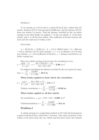
4.3 The brakes are applied to all the four wheels
Figure 5: Motion of the vehicle up the inclined plane and the brakes are
applied to all the four wheels
FA = Brakingforceprovidedbythefrontwheels = µ.RA, FB = µRB
By resolving forces parallel and perpendicular to the plane as above we
get the value of RA and RB :-
RA =
m.g cos α(µ.h + x)
L
and RB = m.g cos α[
L − µh − x
L
]
The retardation ”a” is given by equation, a = g(µ cos α ± sin α), +ve
when vehicle is moving up the plane and -ve when vehicle moving down the
plane. When α = 0 ie; when vehicle moving on plane surface the retardation
a = µg
7](https://image.slidesharecdn.com/brake-170510061602/85/Brakes-and-dynamometers-9-320.jpg)

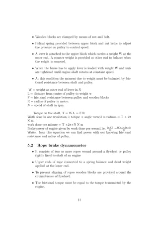
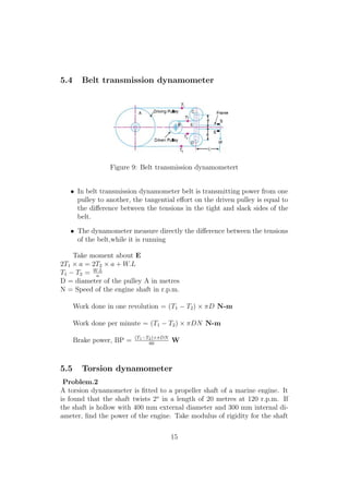
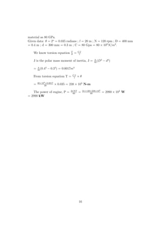

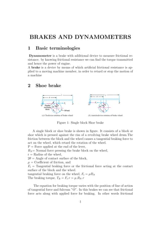
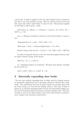
This document discusses various types of brakes and dynamometers used in mechanical engineering. It describes shoe brakes, internally expanding shoe brakes, and how braking works when applied to rear wheels only, front wheels only, or all wheels of a vehicle. It also covers different types of dynamometers used to measure power including pony brake, rope brake, epicyclic train, belt transmission, and torsion dynamometers. Example problems are provided to calculate braking torque and distance required to stop a vehicle under different braking conditions.


