The document discusses the Blended Wing Body (BWB) aircraft, which integrates wings and fuselage to enhance lift and fuel efficiency, potentially accommodating up to 800 passengers. It outlines the historical context, design advantages, and disadvantages of BWB compared to conventional aircraft, emphasizing its aerodynamic benefits and challenges related to structural integrity and passenger safety. The future scope suggests BWB could address rising air traffic demands with innovative thrust mechanisms and reduced environmental impact.


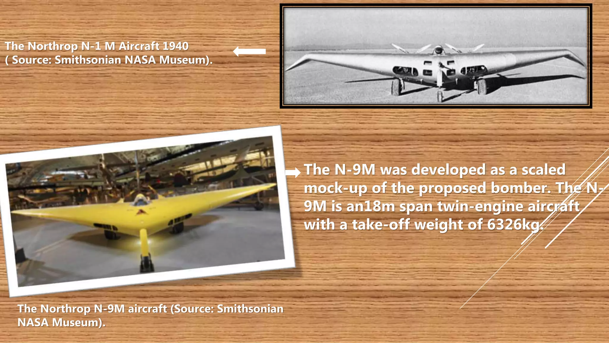
![Northrop N1M “Jeep”, by Northrop Corporation, USA
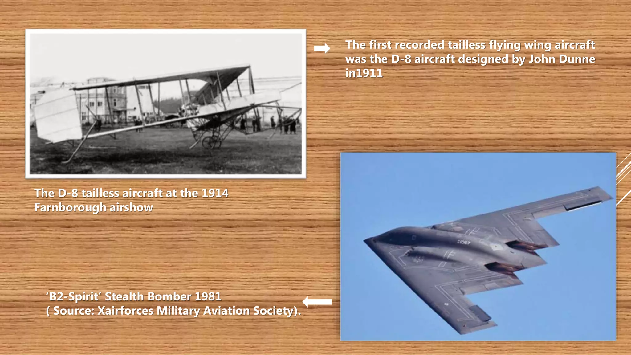
The concept of Blended Wing
body was introduced almost
27 years ago.
The idea was to build a new type of
aircraft that would allow the aircraft
to carry more passengers.
[1]](https://image.slidesharecdn.com/blendedwingbody1-161122055539/75/Blended-Wing-Body-BWB-Future-Of-Aviation-5-2048.jpg)


![The wake of a Boeing 767
disrupts the top
of a cumulus cloud and clearly
shows the
counter-rotating trailing
vortices.[2]](https://image.slidesharecdn.com/blendedwingbody1-161122055539/75/Blended-Wing-Body-BWB-Future-Of-Aviation-14-2048.jpg)


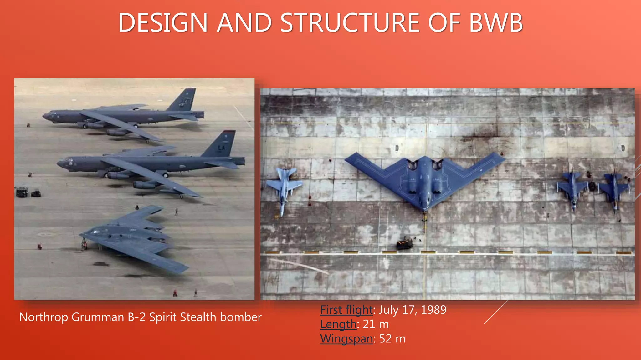
![DESIGN AND STRUCTURE OF BWB
[3]
[4]
[5]](https://image.slidesharecdn.com/blendedwingbody1-161122055539/75/Blended-Wing-Body-BWB-Future-Of-Aviation-23-2048.jpg)
![VELA 2 baseline
concept[6]](https://image.slidesharecdn.com/blendedwingbody1-161122055539/75/Blended-Wing-Body-BWB-Future-Of-Aviation-24-2048.jpg)
![DESIGN AND STRUCTURE OF BWB
Cambridge MIT silent aircraft concept
(Source: The Cambridge-MIT Institute). [7]
The ACFA BWB configuration
The project called Active Flight Control for Flexible
Aircraft is the design of an innovative ultra efficient 450
passenger capacity BWB aircraft with highly swept back
center-body and 2 podded turbofan engines [8]](https://image.slidesharecdn.com/blendedwingbody1-161122055539/75/Blended-Wing-Body-BWB-Future-Of-Aviation-25-2048.jpg)
![DESIGN AND STRUCTURE OF BWB
CONCEPT OF WINDOWLESS
AIRCRAFT[9]
BWB CONCEPTUAL SEATING
ARRANGEMENT[10]
BOEING X48C PROTOTYPE (2011)[11]](https://image.slidesharecdn.com/blendedwingbody1-161122055539/75/Blended-Wing-Body-BWB-Future-Of-Aviation-26-2048.jpg)
![CONVENTIONAL AEROPLANES VS BWB
Transformation of a 650m2
ball into a conventional and
BWB aircraft [12]](https://image.slidesharecdn.com/blendedwingbody1-161122055539/75/Blended-Wing-Body-BWB-Future-Of-Aviation-27-2048.jpg)
![PERFORMANCE COMPARISON
BETWEEN A CONVENTIONAL
AND BWB CONFIGURATION[14]
[13]](https://image.slidesharecdn.com/blendedwingbody1-161122055539/75/Blended-Wing-Body-BWB-Future-Of-Aviation-28-2048.jpg)
![LIFT Vs WEIGHT
DISTRIBUTION
[15]
[16]
[17]](https://image.slidesharecdn.com/blendedwingbody1-161122055539/75/Blended-Wing-Body-BWB-Future-Of-Aviation-29-2048.jpg)
![NO WINDOWS!!!
Each seat will have a multifunctional
LCD screen on the seat in front of them. A
selector will allow the passenger to select from a
number of views, including looking to the rear
and straight down.
It can be used as a cargo plane as it has large
space and there is no problem of internal
pressurization.
[18]](https://image.slidesharecdn.com/blendedwingbody1-161122055539/75/Blended-Wing-Body-BWB-Future-Of-Aviation-30-2048.jpg)
![ADVANTAGES AND DISADVANTAGES OF BWB
ADVANTAGES :-
Aerodynamics: The aerodynamic benefits of the
BWB are derived from the integration of its
‘fuselage’ and wings to obtain ‘low wetted
surface area to volume ratio’ and reduced
interference drag.
This lowers total drag and provides higher L/D
ratio compared to conventional configuration
DOC- direct operating costs includes
Fuel
Landing fees
Maintenance
Annual inspection
[19]](https://image.slidesharecdn.com/blendedwingbody1-161122055539/75/Blended-Wing-Body-BWB-Future-Of-Aviation-31-2048.jpg)

![ADVANTAGES AND DISADVANTAGES OF BWB
DISADVANTAGES :-
High bending stresses resulting from
the effect of pressure on the box-like
shape of the BWB
High bending stress associated
with a non-cylindrical pressure
vessel.
typical aircrafts have a cylindrical shape which requires less strength and is
easier to pressurize as opposed to the interior shape of a BWB.
[20]](https://image.slidesharecdn.com/blendedwingbody1-161122055539/75/Blended-Wing-Body-BWB-Future-Of-Aviation-33-2048.jpg)