
Recommended
Recommended
More Related Content
Similar to DIFFERENTTYPESOFWINGLETSANDTHEIRCORRESPONDINGVORTICES.pptx
Similar to DIFFERENTTYPESOFWINGLETSANDTHEIRCORRESPONDINGVORTICES.pptx (20)
Recently uploaded
Recently uploaded (20)
DIFFERENTTYPESOFWINGLETSANDTHEIRCORRESPONDINGVORTICES.pptx
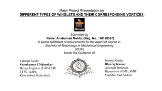
- 1. External Guide: Shamkumar J Mahurkar Design Engineer (CAD/CFD) TTRC, AAPL Khairatabad, Hyderabad Internal Guide: Dheeraj Kumar Assistant Professor Department of ME, SMIT Majhitar, East Sikkim Major Project Presentation on DIFFERENT TYPES OF WINGLETS AND THEIR CORRESPONDING VORTICES Submitted by Name: Anshuman Mehta; (Reg. No. : 20120397) In partial fulfillment of requirements for the award of degree in Bachelor of Technology in Mechanical Engineering (2016) Under the Guidance of
- 2. ABSTRACT • A preliminary CFD study was conducted to compare the wingtip vortices and induced drag generated by ten wing- configurations at cruise conditions. • The geometry for a wing without winglet, wings with simple rounded, aft swept, down-swept, upswept, blended, drooped, fenced, circular and raked winglets were modelled in CATIA and numerically analysed using FLUENT CFD software. • The results produced detailed contour and vector plots of the wingtip vortices magnitudes created by each wingtip configuration.
- 3. CONTENTS 1.ABSTRACT 2.PROBLEM STATEMENTS 3.INTRODUCTION 1.WINGTIP VORTICES FORMATION 2.WINGLETS 4.PROCEDURE 5.AIRCRAFT CONSIDERED 6.DESIGN 7.MESH 8.BOUNDARY CONDITIONS AND MODEL 9.RESULTS 10.CONCLUSIONS
- 4. Problem Statements • There is presence of induced drag due to wingtip vortices which leads to more fuel consumption. • The encounter of an aircraft during take- off or landing with the wake generated by the preceding aircraft can pose a serious hazard which is particularly dangerous because it occurs near the ground. • To avoid wake encounters, regulations require aircraft to maintain set distances behind each other and set time intervals between landing and take-off. As a result of this, the operating costs to airlines and passengers are also severely impacted. • There are also presence of noise effects due to vortex effects
- 5. 5 WINGTIP VORTICES FORMATION • Vortices form because of the difference in pressure between the upper and lower surfaces of a wing that is operating at a positive lift. Since pressure is a continuous function, the pressures must become equal at the wing tips. The tendency is for particles of air to move from the lower wing surface around the wing tip to the upper surface (from the region of high pressure to the region of low pressure) so that the pressure becomes equal above and below the wing. • The air experiences a circular movement along with simultaneous free stream movement resulting in the formation of a helical path.
- 6. 6 WINGLETS A winglet is a (near) vertical extension of the wing tips. Designed as small airfoils, winglets reduced the aerodynamic drag associated with vortices that develop at the wingtips as the airplane moves through the air. By reducing wingtip drag, fuel consumption goes down and range is extended. Aircraft of all types and sizes are flying with winglets.
- 7. 7 Pre- Requirements Design Phase Meshing Phase Boundary Conditions and Model Results Wing Parameters (Wing reference area, number of wings, vertical and horizontal positions relative to the fuselage, cross section of airfoils, aspect ratio, taper ratio, tip chord, root chord, mean aerodynamic chord (MAC), span, twist angle, sweep angle, dihedral angle, incidence angle and other wing accessories) Winglets Designed: - Wing without winglet and with winglets (Aft swept, Blended, Circular, Upswept, down swept, Drooped, Fenced, Simple Rounded, Raked) STEP 1: Initial Meshing STEP 2: Inflation (First Boundary Layer to be provided by calculating by y plus wall distance estimation) STEP 2: Sphere of influence (Body Sizing) STEP 3: Modifications to the meshing such that skewness is less than 0.97 with least number of nodes and elements Density based solver, steady state, Energy ON, Model- Spalart Allmaras method, Mach no. 0.8, Boundary far field method (Calculations of Static Pressure and Temperature), Static Pressure = 66471.39048 Pa, Static Temperature = 275.7092199 K In form of contours, vector plots etc. PROCEDURE
- 8. 8 AIRCRAFT CONSIDERED Aircraft Considered Boeing 777 300 ER Model C Market version of 300 Wingspan 64.86 m Wing Sweepback Angle 37.68 degrees Fuselage Width 6.20 m Typical Cruise speed Mach 0.84 Maximum Speed Mach 0.89 Engine (×2) GE90-115B1 Turbofan, which is the world’s most powerful jet engine in service, with a maximum thrust of 513 kN Root Chord 12.00912 m Tip Chord 1.759 m
- 9. 9 DESIGN Section Air foils used Outboard b737d-il (wrinkle formation) GIII-BL86 Plank form b737b-il Root b737a-il (wrinkle formation) joukowsky0015-jf (closed profile) oaf-139-il (unnecessary vortex formation ) joukowsky001-jf AIRFOIL DETERMINATION All Dimensions are in mm
- 10. The wing geometry used in this study also consisted of multiple aerofoil section, to add to the realism of the model. To preserve accuracy of the computational results, the aerofoils used in the criterion of the geometry of the wing were based on the aerofoil sections used by conventional commercial airliners. However engine is not attached to the wing to keep the area of consideration at the tips only. Design of Reference Wing
- 11. 11 11 Design of Wingtip Devices Simple Rounded Wingtip Upswept Wingtip Raked Winglet Circular Winglet Drooped Winglet Downswept Wingtip Aftswept Wingtip Fenced Winglet Blended Winglet
- 12. 12 Wing Domain Hemisphere Diameter = 10 × Chord Length domain_symmetry pressure_far_field domain_wall Domain and Named Selection
- 13. 13 MESH Maximum Skewness < 0.97 Maximum Aspect Ratio < 700 Overall Mesh Inflation Layers Sphere of Influence
- 14. 14 BOUNDARY CONDITIONS AND MODEL Double Precision OFF Type Density Based Velocity Formulation Absolute Time Unsteady Gravity OFF Energy ON Viscous Model Spalart Allmaras (1 Eq.) Default Configuration Fluid Air Density Ideal Gas Viscosity Sutherland (3 Coefficient) Operating Pressure 0 Pascal Boundary Condition Pressure Far Field Static Pressure = 66471.39048 Pascal Static Temperature = 275.709219 Kelvin Mach Number = 0.8 Turbulent Intensity = 4.16 % Turbulent Length Scale = 12.00912 m
- 15. 15 The wing without winglets configuration displayed a high vorticity concentration throughout the wake region. RESULTS WING WITHOUT WINGLET
- 16. 16 However, the vortex wake for the wing with winglets configuration had the low vorticity in the spanwise direction when compared to the clean wing. Also if we observe carefully the wing with winglet displayed dispersion of vorticity. Simple Rounded Wingtip Aftswept Wingtip Downswept Wingtip
- 17. 17 Upswept Wingtip Fenced Winglet Circular Winglet Blended Winglet Drooped Winglet Raked Winglet
- 18. Additionally, the vortex wake of the wing with winglets configuration was more concentrated than the other nine wing-configurations, indicating that the energy of the vortex wake was conserved. By conserving and focusing the energy of the vortex wake aft of the aircraft, a component of thrust in the forward direction of flight would result. Wing without Winglet Simple Rounded Wingtip Aftswept Wingtip Downswept Wingtip
- 19. 19 Upswept Wingtip Drooped Winglet Blended Winglet Fenced Winglet Circular Winglet Raked Winglet
- 20. 20 CONCLUSION • The air in the vortex flow in anticlockwise direction indicating that air is moving from the lower wing surface around the wing tip to the upper surface (from the region of high pressure to the region of low pressure) • This study has shown that clean wing configuration, i.e., wings without wingtip devices, produce the highest vorticity magnitudes when compared to wing configurations that employ winglets.
- 21. 21 WINGTIP VORTICES VIDEO WITH WING WITHOUT WINGLET WINGTIP VORTICES VIDEO WITH AFTSWEPT WINGTIP
- 22. 22 • The vortex wake generated by clean wing configurations reduce the aspect ratio of the wing, thereby increasing the induced drag on the wing. The winglet designs employed in this study demonstrate the potential to produce a component of force in the thrust direction of the aircraft by concentrating the otherwise turbulent and chaotic vortex flow behind the wingtips into a more energy- efficient flow, thereby counteracting the drag on the wing. • This reduction of the induced drag on an aircraft’s wing offer advantages in terms of an aircraft’s performance including improved fuel efficiency, increased range, and reduced wing loading.