![Benefits Summary
HyperMesh is the promising software for our TC hydraulic performance simulation. It is reducing the
preprocessing hours considerably when CFD model is bigger than 12 deg.
In other end, AcuSolve has inbuilt preprocessor and has single GUI for meshing and solving. It
avoids mesh export from preprocessor and import to solver time. And it eliminates clean-up and mesh
quality improving time.
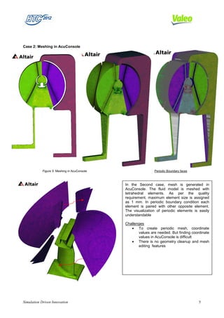
Challenges
Initially we faced periodic definition issue for our fluid model in AcuSolve. For post processing the
contours and vectors, we need to use HyperView separately. If it is inbuilt in AcuSolve, then it will be more
convenient. AcuSolve help documentation is not in detail about features and improvement is needed.
Future Plans
We are planning to validate further HyperMesh for our TC simulation meshing automation. Also we
are planning to validate AcuSolve for other periodic angles like 36 deg, 120 deg and full model simulation to
understand the results variations & correlation with test measurement.
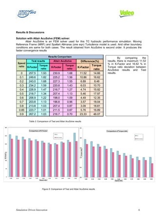
Conclusions
We are looking for complete automation for TC hydraulic performance simulation. So we are
validating AcuSolve competency for our process. It shows that AcuSolve can be confidently used to
compare two or more designs for identifying better design quickly. However, difference between AcuSolve
and test measurement is slightly larger than our current process software. We hope it will be improved by
appropriate solver settings and in future release versions.
ACKNOWLEDGEMENTS
The authors would like to thank Altair Engineering, India for providing technical support in Altair
AcuSolve. The authors would also like to thank Mr.Sriram, R&D Director and Bagath Singh R, engineering
Manager, Power Train Transmissions, VIPL, Chennai for their constant encouragement
REFERRENCES
[1] Versteeq H.K. and W. Malalasekara “An Introduction to Computational Fluid Dynamics”, Longman Group Ltd, 1995.
[2] Ubaldi M., Zunino P., Barigozzi G. and Cattanei A., "An Experimental Investigation of Stator Induced Unsteadiness on
Centrifugal Impeller Outflow", Journal of Turbo machinery, vol.118, 41-54, 1996.
[3] Ramamurthi, V., “Finite Element Method in Machine Design”, Narosa Publishing House, January 2009,
ISBN: 978-81-7319-965-3
[4] Combès, J.F., Bert, P.F. and Kueny, J.L., "Numerical Investigation of the Rotor-Stator Interaction in a Centrifugal
Pump Using a Finite Element Method", Proceedings of the 1997 ASME Fluids Engineering Division Summer Meeting,
FEDSM97-3454, 1997.
Simulation Driven Innovation 7](https://image.slidesharecdn.com/cfd-fem-09compatibilityandaccuracyofmeshvaleo-120914043941-phpapp01/85/Cfd-fem-09-compatibility-and_accuracy_of_mesh_valeo-7-320.jpg)

This document compares mesh generation and CFD simulation results for a torque converter using HyperMesh and AcuSolve. It describes generating meshes of the torque converter components in HyperMesh and AcuConsole, then simulating the flows using FVM and FEM solvers. The results from both methods are compared to test data. The goal is to determine the most suitable meshing and simulation platform for modeling torque converter performance to reduce time spent on CFD projects.


