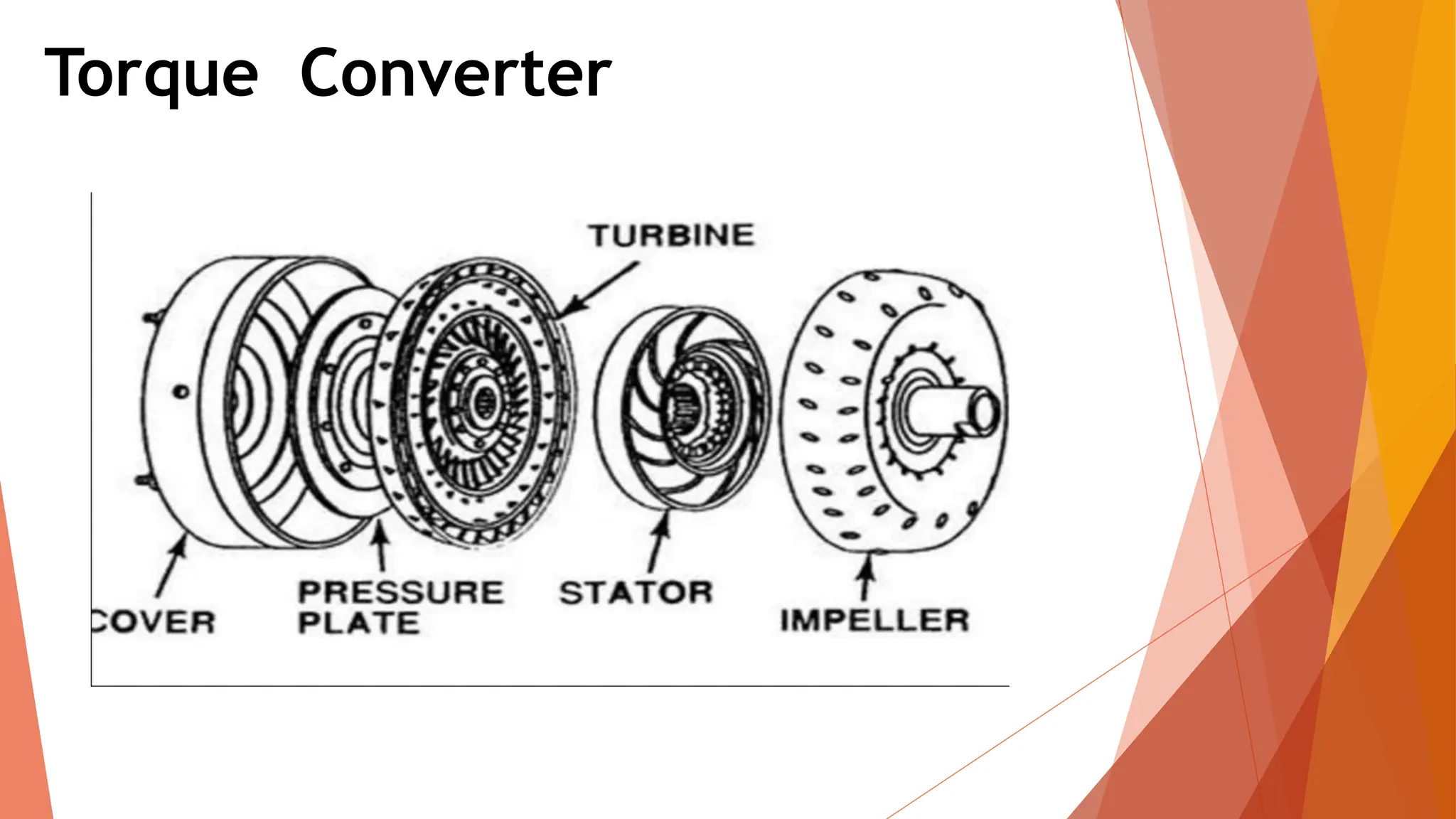
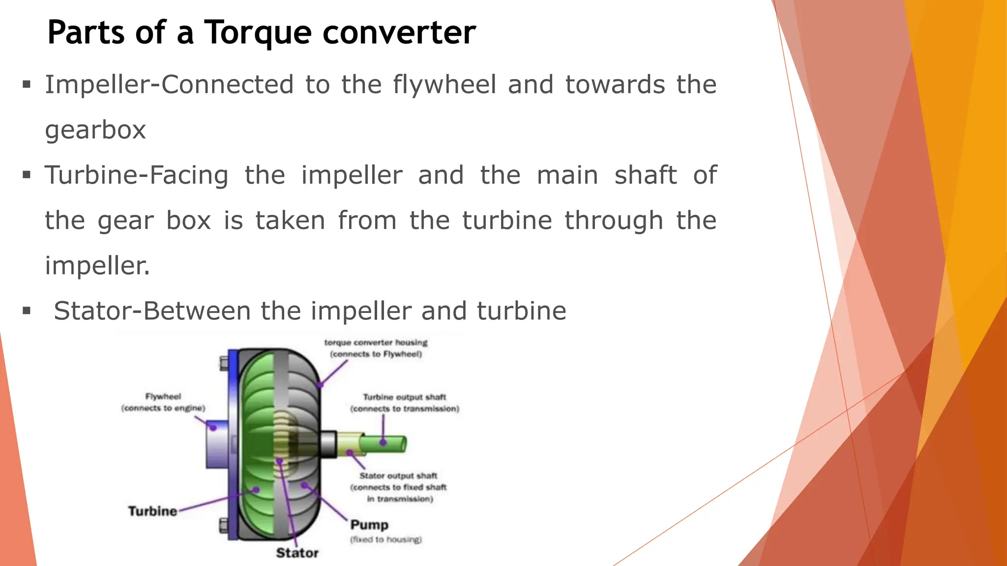
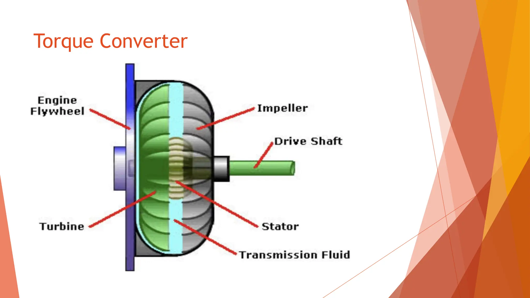
The document discusses automatic transmissions and torque converters. It provides details on:
- The main components of a torque converter including the impeller, turbine, and stator.
- How torque multiplication occurs in a torque converter through vortex fluid flow redirected by the stator.
- The different phases of torque converter operation from torque multiplication to coupling based on speed ratio.
- Other topics covered include stall speed, normal operation, and the role of the flexplate and transmission input shaft.
A torque converter is a fluid coupling used in automatic transmissions that transfers power from the engine to the transmission. It contains an impeller connected to the engine, a turbine connected to the transmission, and a stator in between. In different operating modes like stall and acceleration, the torque converter can multiply torque to help vehicles start moving or can act like a fluid coupling at higher speeds. Problems that can occur include overheating, stator clutch issues, blade damage, and housing distortion from extreme operating conditions.
This document is a seminar report on torque converters that includes:
1) An introduction describing torque converters and their role in automatic transmissions.
2) Descriptions of the major components of a torque converter including the impeller, turbine, and stator.
3) An explanation of how torque converters function in stall, acceleration, and coupling phases.
The document discusses electric drives and their components. It describes:
- Power modulators regulate power from the source to the motor. The control unit controls the power modulator and protects the drive. Sensing units measure parameters like motor current and speed.
- Drives have advantages like wide speed/torque ranges and flexible control. Disadvantages include high initial cost and vulnerability to power failures.
- Drives are classified as group, individual, or multi-motor depending on how many motors are used.
- Dynamics of the motor-load combination are described by the torque equation relating motor torque, load torque, and dynamic torque.
- Steady state stability depends on motor torque exceeding load torque
The document discusses electric drives and their components. It describes:
1) The power modulator regulates power from the source to the motor and restricts current during transients to prevent overloading. It converts energy as needed and selects motoring or braking mode.
2) The control unit controls the power modulator and generates protection commands. It takes input commands to adjust the operating point.
3) The sensing unit measures parameters like motor current and speed for protection or closed-loop control.
Unit I Introduction to Solid State Drives.pptxssuser41efab1
The document discusses electric drives and their characteristics. It describes the key parts of electric drives including the power modulator, control unit, and sensing unit. The power modulator regulates power from the source to the motor. The control unit controls the power modulator and protects the system. The sensing unit measures parameters like motor current and speed. Electric drives offer advantages like wide operating ranges and flexible control but have higher initial costs than other drive types. Load torques on electric drives include friction, windage, and torque for useful work. Drives can operate in different modes including constant torque, constant power, and all four quadrants of the speed-torque plane. Both steady state and transient stability are important considerations.
The document discusses the torque converter and its role in automatic transmissions. It explains that the torque converter uses transmission fluid to transfer power from the engine to the transmission hydrodynamically. The torque converter contains an impeller connected to the engine, a turbine connected to the transmission input shaft, and a stator that redirects the fluid flow to multiply torque. The automatic transmission also contains a planetary gearset and hydraulic controls to shift gears without a clutch pedal.
The document provides an overview of automotive transmission systems, including their main components and functions. It discusses the purpose of the transmission to transmit power from the engine to the driving wheels through a system of gears that allows for different speed and torque ratios. The key components covered are the clutch, gearbox, driveshaft, differential, and axle. Manual, automated manual, automatic, continuously variable, and dual-clutch transmissions are also summarized.
The document discusses the transmission system of an automobile. It defines the transmission system as the mechanism that transmits power from the engine to the driving wheels. The main components of the transmission system are the clutch, gearbox, propeller shaft, universal joints, rear axle, wheels, and tires. The document also discusses different types of transmission systems, including hydraulic transmission systems like fluid couplings and torque converters. It provides details on how manual and automatic transmissions work, including the stages involved and a comparison of the two systems.
The document discusses DC compound motors. A DC compound motor combines features of series and shunt motors by having both a series field winding connected in series with the armature and a shunt field winding connected in parallel. This allows the motor to have the high starting torque of a series motor and the regulated speed of a shunt motor. There are two main types - long shunt and short shunt - depending on how the shunt winding is connected. Compound motors can also be cumulative, where the magnetic fields reinforce each other, or differential, where they oppose each other. Cumulative compound motors are widely used industrial applications like elevators that require both high starting torque and speed regulation.
The document discusses the transmission system of automobiles. It defines the transmission system and its main components which transmit power from the engine to the driving wheels. These include the clutch, gearbox, propeller shaft, universal joints, rear axle, and differential. It describes the requirements of an effective transmission system and the operating principles of different types of transmission systems including manual, automatic, hydraulic, and their main units.
The document discusses the transmission system of automobiles. It defines the transmission system as the mechanism that transmits power from the engine to the driving wheels. The main components of the transmission system are identified as the clutch, gearbox, propeller shaft, universal joints, rear axle, and wheels/tires. The requirements of the transmission system and the types of transmission systems including manual, hydraulic, and automatic are also summarized.
The document discusses the transmission system of automobiles. It defines the transmission system and its main components which transmit power from the engine to the driving wheels. These include the clutch, gearbox, propeller shaft, universal joints, rear axle, and differential. It describes the requirements of an effective transmission system and provides details on manual and automatic transmission systems, including their components and operating principles. It also compares manual and automatic transmissions.
The document discusses the transmission system of automobiles. It defines the transmission system as the mechanism that transmits power from the engine to the driving wheels. The main components of the transmission system are identified as the clutch, gearbox, propeller shaft, universal joints, rear axle, and differential. The document also discusses the requirements of an effective transmission system and describes the operating principles of different types of transmission systems, including manual transmission, hydraulic transmission using fluid couplings or torque converters, and automatic transmission using planetary gears.
1. Electrical drives are systems used for motion control that employ electric motors as prime movers.
2. The key components of an electrical drive system are the power source, power processor/modulator, motor, load, control unit, and sensing unit. The power modulator converts and regulates power from the source for use by the motor according to the demands of the load.
3. Electrical drives can operate in any of the four quadrants defined by positive or negative speed and torque. The motor provides positive or negative torque to accelerate, decelerate, or maintain the speed of the load as needed.
The document discusses various components and types of automotive transmissions. It begins by explaining the basic functions of a transmission system which includes disconnecting the engine from the driving wheels, varying the leverage between the engine and wheels, and allowing the wheels to rotate at different speeds. It then discusses different transmission types such as manual, automatic, automated manual (AMT), continuously variable (CVT), and dual clutch (DCT). For manual transmissions, it focuses on components like the clutch, gearbox, synchronizers, and how they work together. It provides details on automatic transmission components including the torque converter, planetary gear sets, wet clutches and brakes used for gear changes.
The document discusses new trends in internal combustion engines to improve fuel economy, safety, emissions and noise/vibration. These trends include cylinder deactivation to reduce pumping losses under light loads, direct fuel injection for lean combustion and lower emissions, variable valve timing and lift to optimize power and efficiency, and turbochargers to force more air into the cylinders and increase power output. While improving performance, these technologies also increase costs and complexity of engine design and maintenance. The internal combustion engine will likely continue powering vehicles with advanced technologies to meet future challenges.
The document discusses new trends in internal combustion engines to improve fuel economy, safety, emissions and noise/vibration. It describes technologies like cylinder deactivation to improve efficiency by deactivating cylinders under light loads, direct fuel injection for cleaner combustion, variable valve timing and lift to optimize performance, and turbochargers to boost power density. While making engines more complex, these technologies allow internal combustion engines to meet stricter emissions standards while enhancing fuel economy and performance.
Cooperative Control Of Drive Motor And Clutch For Gear Shift Of Hybrid Electr...MOHAMMED SAHAD
This focuses on the cooperative control of the drive motor and clutches for the gear shift of a parallel hybrid electric vehicle (HEV) with dual-clutch transmission (DCT). To achieve outstanding gear shift performance, a HEV with DCT powertrain requires sophisticated control of two clutch actuators and power sources. To improve shift quality, a new shift control strategy based on feedback of both speed and torque states is implemented in this slide.
This document provides an overview of the key topics covered in an automatic transmission diagnosis course. It describes the function of major automatic transmission components like the torque converter and its three parts, planetary gear sets and how they provide different speed and torque ratios, and the types of clutching devices used to hold gears including multi-plate clutches, brake bands, and one-way clutches. It also explains how these components work together to provide the gear ratios used in automatic transmissions.
An automatic transmission uses a torque converter, gear train, and hydraulic system to shift gears automatically based on engine load and vehicle speed. The torque converter connects the engine to the transmission and transfers power through fluid. It multiplies torque for better acceleration. The gear train includes planetary gear sets that provide multiple gear ratios. Hydraulic pressure acts through the transmission fluid to engage clutches and bands, producing gear shifts without driver input as the vehicle speed increases.
An induction motor is a common electric motor where the rotating magnetic field in the stator induces current in the rotor to generate torque. It has a simple and rugged construction, is very reliable and cost-effective. Induction motors are widely used in industrial equipment and household appliances. The current induced in the rotor depends on factors like slip and magnetic saturation, which influence the motor's speed-torque characteristics. Finite element analysis is useful for investigating these characteristics during design. While induction motors are commonly used, their modeling involves complexities like rotor skew, harmonic effects, and nonlinear materials behavior.
1) Rolling mills require motors that can produce heavy torque at low RPM to roll metal ingots into blooms or slabs. DC motors are well-suited as they can provide high starting torque and wide speed variation.
2) Paper mill drives need variable speed control of multiple rolls. Synchronous motors connected via a Schrage motor allow independent yet coordinated speed control.
3) Marine drives utilize electric propulsion motors like induction or synchronous types to independently power propellers via alternators, providing flexibility and economical operation.
Automobile fluid coupling and torque converterDeepak Solanki
1) The document discusses fluid couplings and torque converters used to transmit power between shafts without a rigid connection.
2) A fluid coupling uses an impeller and turbine runner enclosed in a casing filled with fluid. Torque is transmitted from the impeller to the turbine via centrifugal force on the fluid.
3) A torque converter is similar but can vary the output torque through a reaction vanes between the impeller and turbine. This allows torque and speed transformation between input and output shafts.
The transmission system transmits power from the engine's crankshaft to the driving wheels. It consists of several components that work together to smoothly and efficiently transfer the rotary motion from the engine to the wheels. The transmission system converts the reciprocating motion of the pistons into rotational motion, allows the driver to control engagement and disengagement from the engine via the clutch, and uses gearing to gradually adjust the speed and torque delivered to the wheels for different driving conditions.
The AC servomotor is a two-phase induction motor with some special design features. The stator consists of two pole pairs mounted 90 degrees apart, with each pole pair carrying an excitation winding that produces currents with a 90 degree phase difference. A capacitor is used to produce this phase difference. The rotating magnetic field produced interacts with currents induced in the short-circuited rotor conductors, producing a torque that drives the rotor in sync with the rotating field. Key features include a linear torque-speed relationship and positive damping for stable servo operation.
Similar to Torque converter In automobile engineering (20)
Implementing ELDs or Electronic Logging Devices is slowly but surely becoming the norm in fleet management. Why? Well, integrating ELDs and associated connected vehicle solutions like fleet tracking devices lets businesses and their in-house fleet managers reap several benefits. Check out the post below to learn more.
Charging Fueling & Infrastructure (CFI) Program by Kevin MillerForth
Kevin Miller, Senior Advisor, Business Models of the Joint Office of Energy and Transportation gave this presentation at the Forth and Electrification Coalition CFI Grant Program - Overview and Technical Assistance webinar on June 12, 2024.
Charging and Fueling Infrastructure Grant: Round 2 by Brandt HertensteinForth
Brandt Hertenstein, Program Manager of the Electrification Coalition gave this presentation at the Forth and Electrification Coalition CFI Grant Program - Overview and Technical Assistance webinar on June 12, 2024.
Charging Fueling & Infrastructure (CFI) Program Resources by Cat PleinForth
Cat Plein, Development & Communications Director of Forth, gave this presentation at the Forth and Electrification Coalition CFI Grant Program - Overview and Technical Assistance webinar on June 12, 2024.
Welcome to ASP Cranes, your trusted partner for crane solutions in Raipur, Chhattisgarh! With years of experience and a commitment to excellence, we offer a comprehensive range of crane services tailored to meet your lifting and material handling needs.
At ASP Cranes, we understand the importance of reliable and efficient crane operations in various industries, from construction and manufacturing to logistics and infrastructure development. That's why we strive to deliver top-notch solutions that enhance productivity, safety, and cost-effectiveness for our clients.
Our services include:
Crane Rental: Whether you need a crawler crane for heavy lifting or a hydraulic crane for versatile operations, we have a diverse fleet of well-maintained cranes available for rent. Our rental options are flexible and can be customized to suit your project requirements.
Crane Sales: Looking to invest in a crane for your business? We offer a wide selection of new and used cranes from leading manufacturers, ensuring you find the perfect equipment to match your needs and budget.
Crane Maintenance and Repair: To ensure optimal performance and safety, regular maintenance and timely repairs are essential for cranes. Our team of skilled technicians provides comprehensive maintenance and repair services to keep your equipment running smoothly and minimize downtime.
Crane Operator Training: Proper training is crucial for safe and efficient crane operation. We offer specialized training programs conducted by certified instructors to equip operators with the skills and knowledge they need to handle cranes effectively.
Custom Solutions: We understand that every project is unique, which is why we offer custom crane solutions tailored to your specific requirements. Whether you need modifications, attachments, or specialized equipment, we can design and implement solutions that meet your needs.
At ASP Cranes, customer satisfaction is our top priority. We are dedicated to delivering reliable, cost-effective, and innovative crane solutions that exceed expectations. Contact us today to learn more about our services and how we can support your project in Raipur, Chhattisgarh, and beyond. Let ASP Cranes be your trusted partner for all your crane needs!
EV Charging at MFH Properties by Whitaker JamiesonForth
Whitaker Jamieson, Senior Specialist at Forth, gave this presentation at the Forth Addressing The Challenges of Charging at Multi-Family Housing webinar on June 11, 2024.
Expanding Access to Affordable At-Home EV Charging by Vanessa WarheitForth
Vanessa Warheit, Co-Founder of EV Charging for All, gave this presentation at the Forth Addressing The Challenges of Charging at Multi-Family Housing webinar on June 11, 2024.
Understanding Catalytic Converter Theft:
What is a Catalytic Converter?: Learn about the function of catalytic converters in vehicles and why they are targeted by thieves.
Why are They Stolen?: Discover the valuable metals inside catalytic converters (such as platinum, palladium, and rhodium) that make them attractive to criminals.
Steps to Prevent Catalytic Converter Theft:
Parking Strategies: Tips on where and how to park your vehicle to reduce the risk of theft, such as parking in well-lit areas or secure garages.
Protective Devices: Overview of various anti-theft devices available, including catalytic converter locks, shields, and alarms.
Etching and Marking: The benefits of etching your vehicle’s VIN on the catalytic converter or using a catalytic converter marking kit to make it traceable and less appealing to thieves.
Surveillance and Monitoring: Recommendations for using security cameras and motion-sensor lights to deter thieves.
Statistics and Insights:
Theft Rates by Borough: Analysis of data to determine which borough in NYC experiences the highest rate of catalytic converter thefts.
Recent Trends: Current trends and patterns in catalytic converter thefts to help you stay aware of emerging hotspots and tactics used by thieves.
Benefits of This Presentation:
Awareness: Increase your awareness about catalytic converter theft and its impact on vehicle owners.
Practical Tips: Gain actionable insights and tips to effectively prevent catalytic converter theft.
Local Insights: Understand the specific risks in different NYC boroughs, helping you take targeted preventive measures.
This presentation aims to equip you with the knowledge and tools needed to protect your vehicle from catalytic converter theft, ensuring you are prepared and proactive in safeguarding your property.
RACI Matrix Managed Services on Cloud 08-11-19_AS.pdf
Torque converter In automobile engineering
1. Torque Converter
TITLE OF PRESENTATION :
Karmaveer Bhaurao Patil collage of
Engineering Satara.
Department of
Mechanical Engineering
Presented By :
Vishwajit Bhosale
Soham Jadhav
4. INTRODUCTION
.A torque converter is generally a type of
fluid coupling capable of producing torque.
• Replacement of clutch for automatic
transmission vehicle.
5. Impeller-Connected to the flywheel and towards the
gearbox
Turbine-Facing the impeller and the main shaft of
the gear box is taken from the turbine through the
impeller.
Stator-Between the impeller and turbine
Parts of a Torque converter
6. To transmit increased or decreased power
from one shaft to another. A variable
torque is impressed on the driven
Member without the use of gear train or
clutch.
TORQUE CONVERTER:-
Function:-
7. Torque Converter
Automatic transmissions use a torque converter to couple the engine
to the transmission.
• The torque converter:
- Transmits the twisting force or torque delivered to it by the engine
crankshaft
- Multiplies engine torque when additional power is needed
The amount of torque transferred from the engine to the transmission
by the torque converter is directly related to engine rpm.
9. Operational phases
• Stall-The prime mover is applying power to the impeller but the turbine
cannot rotate.
• Acceleration- The load is accelerating but there still is a relatively large
difference between impeller and turbine speed. Under this condition, the
converter will produce torque multiplication
.Coupling- The torque converter is behaving in a manner similar to a
simple fluid coupling.
10. Failure Problems
1. Overheating :-Continuous high levels of slippage resulting
in damage to the seals that retain fluid inside the
converter.
2. Stator clutch breakage:-A very abrupt application of
power can cause shock loading of the stator clutch,
resulting in breakage.
3. Balloning-Operating a torque converter at very high RPM
may cause the shape of the converter’s housing to be
physically distorted due to internal pressure.