Downloaded 18 times
![TABLE OF CONTENTS
HOW THE UNITS OPERATE.. ................ ........ ..... .... ..,.. ,..,.. ,.. ,.... .... ........1
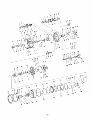
SECTIONAL VIEWS AND PARTS IDENTIFICATION
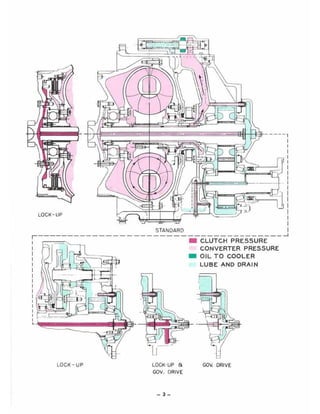
Internal Oil Flow - Torque Converter
Torque Converter Assembly
External Oil Flow - Converter and Transmission
DISASSEMBLY OF THE TORQUE CONVERTER.... ... ...... .................. ..... .. .8
CLEANING AND INSPECTION................ .... ........ ... .. ......... ........ ,..... ,......12
REASSEMBLY OF THE TORQUE CONVERTER.................... ..... ..... .... .... ..13
SERVICING MACHINE AFTER TORQUE CONVERTER OVERHAUL.... ........23
PUMP PRIMING PROCEDURE............. .................,.... .,........ ... ... ...........23
LUBRiCATION ........ ... ... ........... ,... .. ,...,., .........,..,..... ,..... ,.. .. ........... ......24
TABLE OF TORQUE LIMITS............ ....... ,..... ............... .,.. ,.. ............. .... ...24
TROUBLE SHOOTING GUiDE................. ... .. .. .......... ,........ ,.. .................25
RING GEAR INSTALLATION PROCEDURE........... .. .. ... .... .... .. .... ...... ... ... ...29
PROPER OIL CHECKING & FILLING PROCEDURE...... .... .... .......... ...........30
ASSEMBLY INSTRUCTIONS.... ................................ ,..... ,......................32
DRIVE PLATE INSTALLATION INSTRUCTIONS...... .. ................... .......34 & 35
NOTE: Metric Dimensions Shown in Brackets [ ].](https://image.slidesharecdn.com/converterc8000-191019162406/85/Converter-c8000-3-320.jpg)
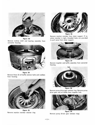
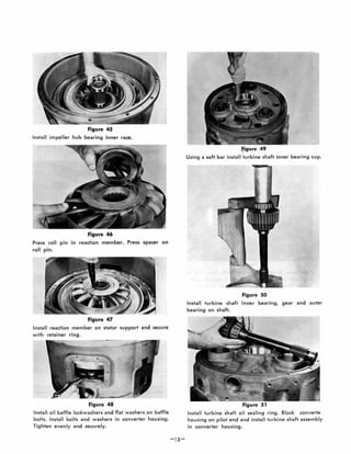
![Figure 52
Position output shaft inner bearing, gear spacer and
gear in converter housing rear cover.
Press outer bearing on output shaft. Turn rear cover
over and position output shaft in output gear and
spacer. Press output shaft into inner bearing.
Apply a thin coat of Permatex No. 2 on the outer
diameter of the output shaft oil seal. Press oil seal in
bearing cap with lip of seal down.
-]6-
Figure 55
Install new "0 11 ring on output shaft bearing cap.
Install bearing cap on output shaft.
Figure 56
Install stud nuts and tighten securely. This is to insure
proper seating of taper bearings.
Figure 57
Loosen stud nuts. Tighten stud nuts evenly finger tight,
this will prevent bearing cap from moving while select-
ing shims. Check gap between bearing cap and rear
cover with shims used as a feeler gauge. REMOVE
sufficient shims to produce a .002" [0,050 mml tight
condition. EXAMPLE: Gap is .0] 0" [0, 254 mm1; final
shim pack thickness to .008" [0, 203 mmJ .](https://image.slidesharecdn.com/converterc8000-191019162406/85/Converter-c8000-19-320.jpg)
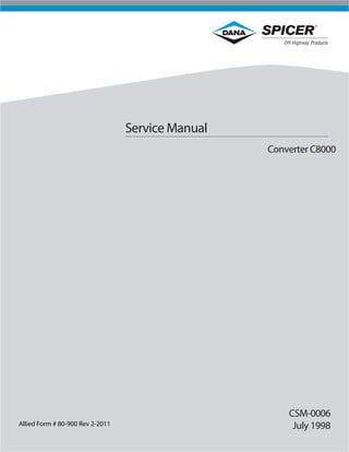
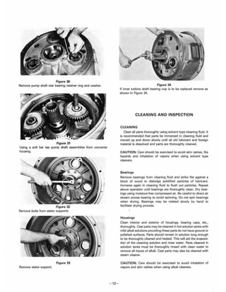
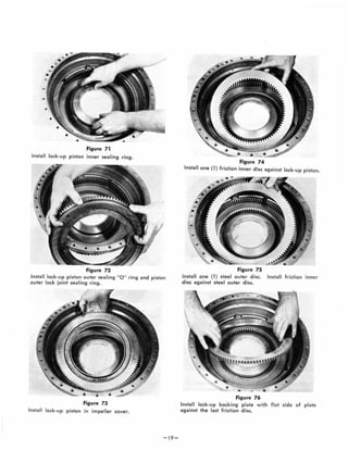
![Figure 58
Install shim pack, bearing cap, stud lockwashe rs and
stud nuts. Tighten nuts to 64 to 70 ft. Ibs. torque
[86,8 - 94,9 N.m] .
Figure 59
Install converter housing to rear cover "0 " ring.
Figure 60
Install rear cover and output shaft on converter hous·
ing.
Figure 61
Install rear cover bolts and lockwashers. Tighten bolts
41 to 45 ft. Ibs. torque [55,6 - 61,0 N.m].
-17-
Figure 62
Using a soft bar, lock converter output gears. Install
output flange, flange 0" ring, washer, and nut.
Figure 63
Tighten flange nut 250 to 300 ft. Ibs. torque [339,0-
406,7 N.m] .
,
•
Figure 64
If governor drive is used, install new oil seal (lip of
seal up) in turbine shaft bearing cap. Install turbine
shaft outer bearing cup in bearing cap.](https://image.slidesharecdn.com/converterc8000-191019162406/85/Converter-c8000-20-320.jpg)
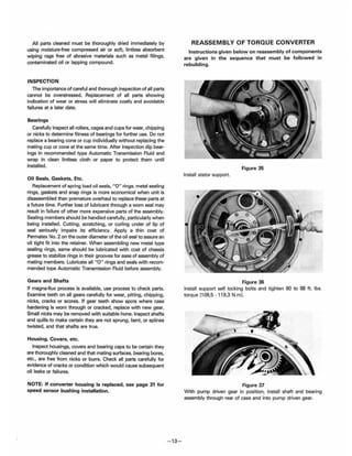
![Figure 65
Install bearing cap on turbine shaft. Install stud nuts
and tighten securely. This is to insure proper seating
of taper bearings.
Figure 66
Loosen stud nuts. Tighten stud nuts evenly finger tight,
this will prevent bearing cap from moving while select-
ing shims. Check gap betwee n bearing cap and rear
cover with shims used as a feeler gauge. ADD sufficient
shims to produce a .002" [0,050 mm] loose condition.
EXAMPLE: Gap is .010" [0,254 mm); final shim thick·
ness to be .012" 304 m Remove bearing caD.
Figure 67
Install adaptor on turbine shaft. NOTE: Adaptor will
. vary for lock - up, lock - up and governor drive, and
governor drive~ Assembly and disassembly is the same
for all. Install bolts and tighten 26 to 29 ft. Ibs. torque
[35,3 - 39,3 N.m).
-1 S-
Figure 68
Install 0 " rings on lube tube (see arrows). Using
bearing cap as a guide for lube tube flange, install
lube tube in rear housing.
Figure 69
With bearing cap shims and new 110 " ring (see arrow)
in position install bearing cap.
Figure 70
Install lockwashers and nuts. Tighten nuts 64 to 70
ft. Ibs. torque [86,S - 94,9 N.m) .
If lock·up is used refer to Figure 71 through S7. If
non lock~ up is used refer to Figures 88 through 94.](https://image.slidesharecdn.com/converterc8000-191019162406/85/Converter-c8000-21-320.jpg)
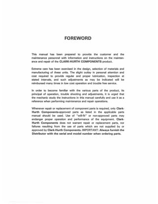
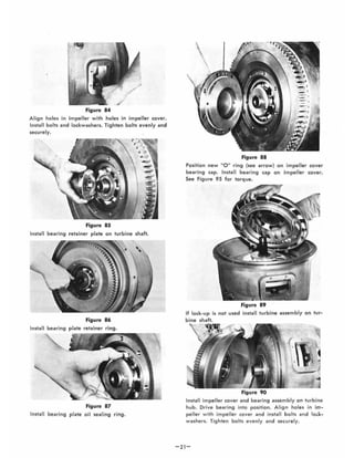
![Figure 77
Install backing plate retainer ring, with split in ring
at lock plate position.
Figure 78
Install retainer ring lock, bolt lock and bolt. Tighten
bolt to 12 to 16 ft. lb•. torque [16,3 - 21,7 N.m]. Bend
tangs of bolt lock over head of bolt.
Figure 79
Install turbine and lock-up hub in impeller cover. Turn
turbine slowly to allow lock-up hub to engage in inner
lock-up discs. Do not force this operation. When tur-
bine is in full position in lock-up discs, turn assembly
over and block turbine to prevent it from dropping
out of position.
-20-
Figure 80
Install impeller cover to turbine hub front bearing.
Figure 81
Install turbine hub dowels.
Figure 82
Position impeller to impeller cover "0 " ring.
Figure 83
Install turbine and lock-up cover on turbine shaft.](https://image.slidesharecdn.com/converterc8000-191019162406/85/Converter-c8000-23-320.jpg)
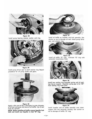
![Figure 91
Install bearing retainer plate.
Install bearing plate retainer ring.
Install new sealing ring expander spring and oil seal-
ing ring on bearing plate. Expander spring gap to be
1800
from sealing ring hook joint.
Position new 0 11
ring on impeller cover bearing cap.
Install bearing cap on impeller cover.
-22-
Figure 95
Install self locking bearing cap bolts in bearing cap
and tighten 52 to 57 ft. lb•. torque [70,5 - 77,3 N.m].
Figure 96
Install pump drive-sleeve and pump on converter
housing rear cover.
Figure 97
Instal l lockwashers and stud nuts. Tighten securely.](https://image.slidesharecdn.com/converterc8000-191019162406/85/Converter-c8000-25-320.jpg)
![SPECIFICATIONS AND SERVICE DATA-POWER SHIFT TRANSMISSION
AND TORQUE CONVERTER
CONVERTER OUT
PRESSURE
CONTROLS
CLUTCH TYPE
CLUTCH INNER DISC
CLUTCH OUTER DISC
Converter outlet oil temp. ISOe • 200" F.
[82.3° • 93,3° CJ.
Transmission in NEUTRAL
Operating specifications:
55 psi [379.3 kPaj minimum pressure at 2000 A.P.M.
engine speed AND a maximum of 70 psi J482.6 kPa]
outlet pressure with engine operating at no-load
governed speed.
Forward and Reverse - Manual
Speed Selection - Manual
Multiple discs, hydraulically actuated, spring released,
automatic wea r com pensation and no adjustment. All
clutches oil cooled and lubricated.
Friction.
Steel.
Oil FILTRATION
CLUTCH PRESSURE
Full flow oil filter safety by-pass. also strainer screen
in sump at bottom of transmission case.
180·220 psi (1241 .1 - 1516,8 kPaj - With parlt.ing
brake set (l ee note) , oil temperature 1BO· • 200· F.
[82.2· • 93.3° CJ. engine at idle (400 to 600 RPM). shift
Ihru direction and speed clutches. All clutch pressure
must be equal within 5 psi. 134,5 kPajlf .clutch pressure
varies in anyone clutch more than 5 psi. [34,5 kPaj repair
clutch.
NOTE: Never use .e!Vice brake. while making
clutch pressure chacks. Units having brake
actuated declutching in forwerd and/or rever••
will not give a t,ue reading.
ALWAyS USE PAR KING BRAKE WHEN MAKING
CLUTCH PRESSURE CHECKS.
LUBRICATION
TYPE OF Oil See lube Chart.
CAPACITY Conlult Operalor's Manual on applicable
machine model for sy$lem capacity. Torque
Converter, Transmission and allied hydraulic
lYltem must be considered al a whole to
determine capedty.
CHECK PERIOD Check oil level DAilY w ith engine running
at 500·600 RPM and oil at 180
0
to 200
0
F.
[82, 2 . 93, 30
C). Maintain oil level to FULL
mark.
NORMAL * Every 500 hours, change oil filter element.
DRAIN PERIOD Every 1000 hours, drain and refill Iystem as
folioWl: Drsin with oil at 1500
to 200
0
F.
[65. 6 , 93. 3° C].
NOTE: It is recommended that filter elements
be changl'ld af'e, so and 100 houff, of op-
• ,ation on new and rebuilt or repaired units.
(.) Drein transmission and remove lump
screen. Clean $Creen thoroughly and
replace, uling new g ukets.
(b) Drein oil filtert, remove end di$Csrd
filter elements. Cleen fi lter . helll end
instell new elements,
(c) Refill trenlmiuion to lOW me.rk.
(d) Run engine et 500·600 RPM to prime
conyerter end lines.
(e) Recheck level with engine running et
SOD . 6OO RPM end edd oil to bring
level to lOW mark. When oil tempere·
ture i. hot (1 80_2000
F.) [82,2_93,30
C]
mek. finel oil level check. IRING OIL
lIYEl TO FULL MARK.
RECOMMENDED LUBRICANTS FOR CLARK·HURTH COMPONENTS POWER SHIFTED
TRANSMISSION AND TORQUI! CONVERTERS
Prevallll'lg Ambie nt Te m pera t ure
,.
,.,.,.
'",.
"Il" :_3:2" :
•
•
•
"
-0.11<010 Ia a ••, 1.-..1 w.o._ 01
13_••' Moto<s C...,.....,;on.
•
•
•
•
•
"
,"
'.
'.
'.-.
(.) 0-2 Ofllde 30
Temperatu,. Ib) 03 Gr.de 30
RI " gl " ' " (e) Engine Oil:·Ofede 30 API·CO/SE or CD/SF
Tempereturl
Rangl
Tlmperet",.
"~,.
T. mp....tul.
"~,.
T.mpe..tur.
R.n9'
Id) MIL·L·2 , Q40Gf.da 30
II) M' L·L·2 ' 040·Grlde 30
I') MIL·L·2'04C·Gfade 10
(b) MIL·L·2 104D-G.-de 10
Ie) 02 Gflde 10
"2" (d) 03 Gr.de 10
(e) Engine OI1:·Grade 10 API'CDISE Of CO/SF
(I) Oul"tolubrie a22·220 INon Phosphate Esler Fife
Resis.an. A uid)
~3" :: :::: It O ' SI' Clution BIlow
..." :: ~:~:~~:::~ A
." 6" II) ~~~~faerlO"TOInce Syn,hetic Motor Oil -
PREFERRED OIL VISCOSITY: SeIaet highe$1oil ~ty compatl•
bIe with pteYtiIing arnIl;enl lempatalures and oil application chart.
TemperatUfe rtIf91S "2" and "3" may be used to Iow( ambianl
lempetillures when sump prOOeaIM are used.
Tempefa'ure range "4" should be used ody in ambianl terflleralOOl
"""-.MODULATED SHIFT TRANSMISSIONS: Tl2000, 18000.24000,
28000 & 32000 lMHies IrOlnsmitslons wilh modula.ed shift use only
C.J or lemperOl'Url range 3 Ilema (al & (b) 'Denon Of ' De~ ron
" O. SEE CAUTION BELOW. 3000. 4000, 5000. 6000. 8000.
16000 &34000 sories 'fllnsmllssions wi.h modulated shift use only
C·3 or lemperalUfe range 3 item (a) only · Oe~ron. Do NOT use
'Dexron II D. SEe CAUTION BELOW.
CAUTION: ' OeXfon II 0 I. no. eompatlble with graphitic: eluteh
pl" e lrlc:l!on materl.1UNLESS IT MEETS THE APpROVED c-3
SPECIFICATIONS. 'Oenon II D nnnol be used In the 30013,
4000,5000,6000, 8000, '8000 or 34000 series power shift
trensmlilions, or the HR28000 & HR32000 series hllYlng eon·
v.rt. r Iock·up. or the C270 . erles eonverter having lock·up
UNLESS IT MEETS THE APPROVED C-3 SPECIFICATIONS.
Any devletion from th'- chert ......1 haw writtMl epprovlll from
the appIlc:atIon departmanl of the C....k·Hurth Cornponenr.
Engineering and Merketlng Deplr1ment.
*Normal drain periods and filter change intervills are for average environmental and duty-cycle conditions_
Severe or sustained high operating temperatures or very dusty atmospheric conditions will c.use .cceler-
ated deterioration and contamination. For extreme conditions iudgment must be used to determine the
required ching. intervol.,
- 24 -](https://image.slidesharecdn.com/converterc8000-191019162406/85/Converter-c8000-27-320.jpg)
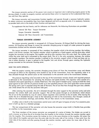
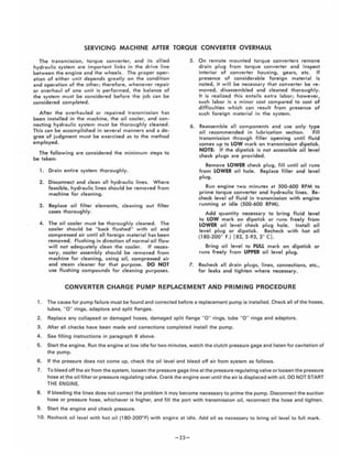
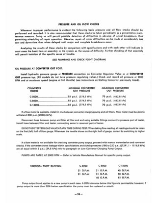
![TORQUE IN (FT.-lBS.)
BOLTS, CAPSCREWS, STUDS AND NUTS
Grade 5 Identification, 3 Radiol
Dashes 1200
Apart on Head of Bolt
Grode 8 Identification, 6 Radiol
Dashes 60° Aport on Head of Boh
LUBRICATED OR PLATED
Grode 5 Grode 8
Nominal Fine Thread Course Thread Fine Thread Course Thread
Size Torque Lbs. Ft./N,m. Torque Lbs. Ft./N.m. Torque Lbs. Ft./N.m. Torque Lbs. Ft./N.m.
.2500 9·11 (12.2·14.9] 8·10 [10.8·13.6] 11 ·1 3(14.9·1 7.6] 9·11 ]12.2· 14.9]
.3125 16·20 ]21 .7·27.1] 12·16116.3·21 .7( 28·32 (38.0·43.4] 26·30 (35.3·40.7]
.3750 26·29 (35.3·39.3] 23·25 (31.2·33.9] 37·41 (50.2·55.6] 33·36 (44.7·48.8(
.4375 41 ·45 (55.6·61.0] 37·4 1 (50.2·55.6] 58·64 [78,6·86.8] 52·57 (70.5·77,3]
.5000 64·70 (86,8·94,9] 57·63 (77,3·85,4] 90·99 (122,0·134,2] 80·88 (108,5· 11 9,3]
.5625 91·100 (123.4·135,6] 82·90 (111 .2·122,01 128·14111 73.5·191,2] 115·127 [1 56,0·172.2]
.6250 128·141 (173,5·191 .2] 113·124(153.2·168,1] 180·198 (244.0·268.4] 159·175 (215,6· 237,3]
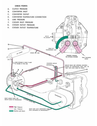
PRESSURE AND OIL FLOW CHECK SPECIFICATIONS. ALL CHECKS
MADE WITH HOT OIL (180.200
0
F,) [82.2 - 93.3
0
C.)
A. Clutch Pressure at Transmission Control Cover See Specifications and Service Data.
See External Oil Flow Diagram.B. Transmission to Converter Line
C. Converter·Out Pressure
D. Temperature Gauge Connection
E. Lubricating Pressure
Converter Return Line
Converter Pump Output
See Pressure and Oil Flow Checks.
See External Oil Flow Diagram.
25 p.s.i. [172.4 kPa] Maximum at High Free Idle,
See External Oil Flow Diagram.
See Pump Chart,
TROUBLE SHOOTING GUIDE
The following data is presented as an aid to locati ng the source of difficulty in a ma lfunctioning unit. It is
necessary to consider the torque converter chargi ng pump, transmission, oil cooler and connecting oil lines as
a complete system when running down the 50urce of trouble since the proper operation of any unit the re in
depends greatly on the cond ition and operation of the others. By 5tudying the principle!:> of operation together
with data in this section, it may be possible to correct any malfunction which may occur i '~ the system.
TROUBLE SHOOTING PROCEDURE BASICA LLY CONSISTS OF TWO CLASSIFICATIONS, MECHANICAL AND
HYDRAULIC.
MECHANICAL CHECKS
Prior to checking any part of the sY5tem from a hydraulic standpoint, the following mechanica l checks should
be made.
1. A check should be made 10 be sure all control lever linka9~ is properly connected and adiusted at all
connecting points.
2. Check shiff levers and rod5 for binding or restrictions in travel that wou ld prevent full engagement. Shift
levers by hand at transm ission case, if full engagement cannot be obtained, d ifficulty may be in control cover and
vcllve assembly.
HYDRAULIC CHECKS
Before checking on the torque converter, trammission and allied hydraulic systems for pressures and rate
of oil flow, it is eS5entiai th at the following preliminary checks be made.
1. Check oil level in transmi5sion. Th is shou ld be done with oi l temperatures of 180·200 ·F. (82,2.93,3:C.1.
DO NOT ATTEMPT THESE CHECKS WITH COLD OIL To bring the oil temperature to this specification it is
necessary to either work the machine or "stall" out the converter. Where the former means is impractical, the
laller means shou ld be employed as follows:
Engage shift levers in forward and high 5peed and apply brakes. Accelerate engine half to three.quarter throttle.
Hold stall until desired converter ou tlet temperature is reached. CAUTION: FUll THROTTLE STAll SPEEDS
FOR AN EXCESSIVE LENGTH OF TIME W ILL OVERHEAT THE CONVERTER,
-25-](https://image.slidesharecdn.com/converterc8000-191019162406/85/Converter-c8000-28-320.jpg)
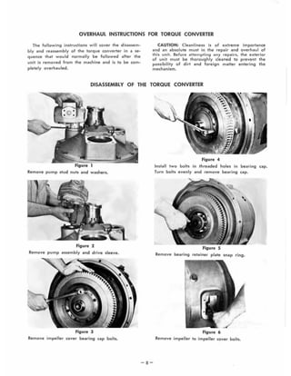
![TRANSMISSION CLUTCH lEAKAGE
Check clutch pressures at low engine idle w ith oil at operating temperatures 180 - 200" F. [82, 2 - 93, 3" C].
Engine speed must remain constant during entire leakage check. Shift lever into forward 4 or 8 speeds. Record
pressures. Shift lever in reverse and 1st. Record pressure. All pressure must be equal within 5 p.s.i. [34.5 kPa].
If clutch pressure varies in anyone clutch more than 5 p.s.i. [34.5 kPaJ , repair clutch.
If a flow meter is available install in line coming out of converter pump. See flow diagram for location of
pressure on flow checks. Check pump volume at 2000 RPM and at low engine idle. Record readings. See pump
volume specifications at 2000 RPM.
Install flow meter in the line coming from transmission to converter. Check oil volume at 2000 RPM and at
(ow idle in the following speed selections. Record readings.
Forward - low speed thru High Reverse - Low speed
Subtract readings in each speed from pump volume reading to get transmission clutch leakage.
EXample, Pump Volume at idle 8 gal. Pump volume
Forward-low speed thru High 6 gal. Forward - Low speed
Reverse-Low speed 6 gal. Clutch leakage
If clutch leakage varies more than 1 gal. from one clutch to another, repair clutch.
CONVERTER LUBE FLOW
LEAKAGE IN TRANSMISSION CLUTCHES
Leakage in 3000 series must not exceed .4 gal. max.
Leakage in 5000 series must not exceed .4 gal. max.
Leakage in 8000 series must not exceed 6 gal. max.
Leakage in 16000 series must not exceed 7 gal. max.
8
6
2
gal.
gal.
gal.
Disconnect CONVERTER DRAIN BACK line at transmission with engine running at 2000 RPM and meaSure
oil into a gallon container. Measure oil leakage for 15 seconds and multiply the volume of oil by four to get
gallons per minute leakage.
LEAKAGE IN CONVERTER
leakage in C270 series not to exceed 2 gal. max.
Leakage in C5000 series not to exceed 3 gal. max.
leakage in C8000 series not to exceed 5 gal. max.
leakage in C16000 series not to exceed 5 gal. max.
LOW CLUTCH PRESSURE WITH NORMAL CLUTCH LEAKAGE
CAUSE
1. low Oi I level.
2. Broken spring in transmission regulator valve.
3. Clutch pressure regulator valve spool stuck in
open position.
4. Faulty charging pump.
REMEDY
1. Fill to proper level.
2. Replace spring.
3. Clean valve spool and sleeve.
4. See paragraph on charging pump output.
LOW CLUTCH PRESSURE WITH EXCESSIVE CLUTCH LEAKAGE
1. Broken or worn clutch piston sealing rtngs.
2. Clutch drum bleed valve ball stuck in open
position.
3. Broken or worn sealing rings on clutch support.
4. low converter charging pump output.
-27-
1. Replace sealing rings.
2. Clean bleed valve thoroughly.
3. Replace sealing rings.
4. See paragraph on charging pump output.](https://image.slidesharecdn.com/converterc8000-191019162406/85/Converter-c8000-30-320.jpg)
![C & CL-8000 TORQUE CONVERTERS
FLYWHEEL RING GEAR INSTALLATION PROCEDURE
@
®
230594
FLYWHEEL
249087
C & CL·8000
249087 229769
230594
2.032 [51.62]
2.094 [53.18]
If Backing Ring is to be replaced order Part No. 230594 Backing Plate.
The 802551 Kit Includes:
1
24
96
24
1
249087
235050
228987
229769
802552
Remove all burrs from Flywheel Mounting Face and Pilot
Bore, clean with solvent.
The engine Flywheel and Housing must conform to standard
S.A.E. NO. 1 - S.A.E. J927 tolerance specifications for Pilot
Bores, Eccentricities and Mounting Face deviations. Check
engine crankshaft "End Play" , must be the same value
before and after the torque converter is mounted to the
engine.
2 Install three (3) Studs 235050 - equally spaced. Tighten 33 to
36 IbUt 144,8 - 48,8 N·m] of torque.
3 Install Ring Gear 249087 by tapping lightly in place.
-29-
Ring Gear
Stud
Belleville Washer
Stud Nut
Instruction Sheet
4 Install remaining studs. Tighten 33 to 36 Ibf.ft [44,8 -
48,8 N'm} torque.
5 Install Backing Plate 230594.
6 Lubricate Stud Threads, Belleville Washers and Nuts with
S.A.E. #1 aoit.
7 Install Belleville Washers and Elastic Stop Nuts as shown
(3 washers, each stud for C & CL-5000 and HR &
LHR-34000; 4 washers, each stud for C & CL-BOOo). Tighten
nuts in a criss cross pattern to 25 IbHt [34 N·ml. Then
tighten nuts in increments of 51bHt 16,7 N·ml in a criss cross
pattern to 35 Ibf.ft 147,5 N·ml for C & CL-5000 and HR &
LHR-34000 and 45lbf·h [61.0 N'm] for C & CL·8000 torque.](https://image.slidesharecdn.com/converterc8000-191019162406/85/Converter-c8000-32-320.jpg)
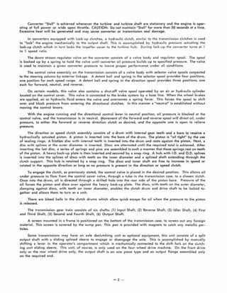
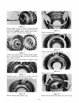
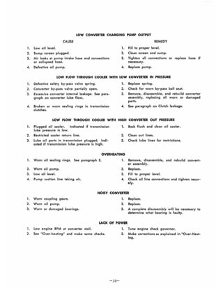
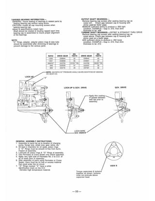
![SPEED SENSOR BUSHING INSTALLATION
VIEW "S" (Output Drive Gear Sensor) REAR VIEW OF CONVERTER
Inspect at assembly.
Dim. " W" from gear tooth.
Stake 3 places approx.
equally spaced.
After curing of Loctite,
speed sensor bushing
must be secure with 40
Ft. Lb. [54.2 N'm] torque. VIEW " T" (Pump Drive Gear Sensor) -+-0-1
Inspect at assembly.
Dim. "U" from gear tooth.
Assemble Speed Sensor Bushing in housing to specified
dimension " U" or " W" with Loctite 262 and stake (3) three
places. See Pump Drive and Output Gear Charts for dimensions.
PUMP DRIVE RATIO
DRIVE GEAR DRIVEN GEAR SPEED SENSOR BUSHING
RATIO NO. OF TEETH NO. OF TEETH DEPTH "U" PER VIEW "T"
1.250 32 40 1.060+ .007 [26.9 ± .17]
1.057 35 37 1.060+ .007 [26.9 ± .17]
.946/25 0
37 (250
PA) 35 (25 0
P.A.) 1.390 ± .007 [35.3 ± .17]
.946 37 35 1.390 + .007 [35.3 + .17]
.800 40 32 1.390 ± .007 [35.3 ± .17]
OUTPUT GEAR RATIO
TURBINE SHAFT OUTPUT
RATIO & GEAR ASS'Y GEAR SPEED SENSOR BUSHING
NO. OF TEETH NO. OF TEETH DEPTH "W" PER VIEW " S"
1.323 31 41 1.060 ± .007 [26.9 ± .1 7]
1.118 34 38 1.060 + .007 [26.9 + .17]
1.000 36 36 1.390+ .007 [35.3 ± .17]
.895 38 34 1.390 ± .007 [35.3 ± .17]
.846 39 33 1.390 1, .007 [35.3 ± .17]
- 31 -](https://image.slidesharecdn.com/converterc8000-191019162406/85/Converter-c8000-34-320.jpg)
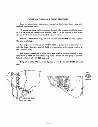
![C & CL8000 Series Converter Drive Plate
INSTALLATION INSTRUCTIONS
Proper Identification by Bolt Circle Diameter
Measure the "A" dimension (Bolt Circle diameter) and order Drive Plate Kit listed below.
INTERMEDIATE
DRIVE PLATES (5)
"AM Dimension (Bolt Circle Diameter)
15.00" [381,000 mm) diameter
Kit No. 802587-10mm
16.00' [406,400 mm) d;ameter
Kit No. 802558-10mm
16.00" [406,400 mm) diameter
Kit No. 802590-7/16-20
16.875" [428,625 mm) diameter
•• Kit No. 802609-7/16-20
17.00" [431,800 mm) diameter
Kit No. 802593-10mm
17.00" [431 ,800 mm) diameter
Kit No. 802562-7/16-20
Each kit will include the following parts:
5 Intermediate Drive Plates
1 Drive Plate Assembly
1 Backing Plate
14 Drive Plate Mounting Capscrews
Instruction Sheet
.. 1 pc. Drive Plate Mounting Spacer is
included in Kit No. 802609.
,
BOLT CIRCLE DI~
O
~· ':" k ...., 0 0
, .. . : ", ..r:JI".- ",,'
""-BACKING RING
INTERMEDIATE
DRIVE PLATES (6)
MN Dimension (801t Circle Diameter)
16.00" [406,400 mm) diameter
Kit No. 802594 W/O Nuts
Each kit will include the following parts:
6 Intermediate Drive Plates
1 Backing Plate
14 Drive Plate Mounting Capscrews
Instruction Sheet
NOTE:Assembly of flexplates must be completed
within a 15 minute period from start of screw
installation. If the screw is removed for any reason
it must be replac;ed. The adhesive left in the tapped
holes must be removed with the proper tap and
cleaned with solvent. Dry the hole thoroughly and
use a new screw for reinstallation.
Pos~ion drive plate and weld nut assembly on Impeller cover with weld nuts toward cover. Align intermediate drive plate and
backing ring with holes in impeller cover. NOTE: Two dimples 180· apart in backing ring must be out (toward engine flywheel).
Install capscrews. Tighten capscrews 52-57 ft·lbs torque [70.4 - 77.1 N·m].
See page 35 for TORQUE CONVERTER TO ENGINE INSTALLATION PROCEDURE
-34-](https://image.slidesharecdn.com/converterc8000-191019162406/85/Converter-c8000-37-320.jpg)
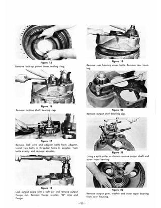
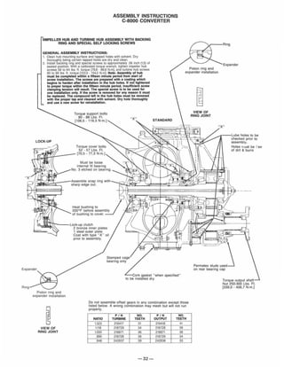
![TRANSMISSION TO ENGINE INSTALLATION PROCEDURE
1. Remove all burrs from flywheel mounting face and
nose pilot bore. Clean drive plate surface with solvent.
Dry thouroughly.
2. Check engine flywheel and housing for conformance
to standard S.A.E. #1 - S.A.E J-927 and J-l033
tolerance specifications for pilot bore size, pilot bore
runout and mounting face flatness. Measure and
record engine crankshaft end play.
3. Install two 3.50 [88,90 mm] long converter to flywheel
housing guide studs in the engine flywheel housing
as shown. Rotate the engine flywheel to align a drive
plate mounting screw hole with the flywheel housing
access hole.
4. Install a 4.00 [101,60 mm] long drive plate locating
stud in a drive plate nut. Align the locating stud in the
drive plate with the flywheel drive plate mounting
screw hole positioned in Step NO.3.
5. Locate converter on flywheel housing aligning drive
plate to flywheel and converter to flywheel housing.
Install converter to flywheel housing screws. Tighten
screws to specified torque. Remove converter to
engine guide studs. Install remaining screws and
tighten to specified torque.
6. Remove drive plate locating stud.
7. Install drive plate attaching screw. Snug screw but do
not tighten. Some engine flywheel housings have a
hole located on the flywheel housing circumference in
line with the drive plate screw access hole. A
screwdriver or pry bar used to hold the drive plate
against the flywheel will facilitate installation of the
drive plate screws. Rotate the engine flywheel and
install the remaining seven (7) flywheel to drive plate
attaching screws. Snug screws but do not tighten.
After all eight (8) screws are installed, tighten each
capscrew to the following torque- 7/16 capscrew 58-
64 ft. Ibs torque [78-86 N.m] :M-l 0 capscrews 48-55 ft.
Ibs torque [65-75 N.m]. This will require rotating the
engine flywheel until the full amount of eight (8)
screws have been tightened.
8. Measure engine crankshaft end play after converter
has been completely installed on engine flywheel.
This value must be within .001 [0,025 mm] of the end
play recorded in Step No.2.
- 35-
FLYWHEEl ll'F='lIHOUSINQ -1
ENGINE
flY~~llI'1---J)
.,'"
FLYWHEEl
FIG t
FIG2
FIG3
-.~ I.
~ F
~
~ I ::J-~ I
••I
I
I
•I
FLYWHEEl
""""""
fLYWHEEL
HOUSING
FLYWHEEL
IMPELLER
COVER
,l!INTERMEDIATE
DRIVE PLATES
/,,'STUD
DRIVE
PLATE
SPECIAL STUD, WASHER AND
SELF LOCK NUT FURNISHED
BY I!NGINE MANUFACTURER.
FIG4
Plates To Be Installed
- With Concave Side
Toward Engine Flywheel.](https://image.slidesharecdn.com/converterc8000-191019162406/85/Converter-c8000-38-320.jpg)


The document provides instructions for maintaining and repairing a Clark-Hurth torque converter. It begins with an overview of how torque converters and transmissions function together in the powertrain to deliver engine power to the wheels. It then provides detailed sectional views and parts identification diagrams to familiarize mechanics with the internal components. The remainder of the document provides step-by-step instructions for disassembling, cleaning, inspecting, and reassembling the torque converter. It also includes troubleshooting guides and other maintenance procedures.


