This is mechanical engineering presentation on power steering system. In this presentation i describe basics of power steering and their history. I hope it will help you for your engineering and you can understand better about mechanical engineering.
Introduction to the Transmission system, Requirements of the transmission system, main units of the transmission system, types of the transmission system, clutch, functions of a clutch, requirements of a clutch, principle of operation of a clutch, friction materials, classification of a clutch, cone clutch, single-plate clutch, multi-plate clutch
centrifugal clutch, hydraulic coupling, hydraulic torque converter.
How to Become a Thought Leader in Your NicheLeslie Samuel
Are bloggers thought leaders? Here are some tips on how you can become one. Provide great value, put awesome content out there on a regular basis, and help others.
The Transmission
Contents
Abstract 3
Introduction 3
Discussion 3
(Automatic-transmission) 3
(Manual Transmission) 5
(Type of Gears) 6
(Gear Ratios) 7
(Transmission and Shaft work) 8
Relative-Motion (Analysis: Velocity) 9
Conclusion 10
References 11
Abstract
The aim of this report is to introduce the types of transmissions and how they operate. A description of the internal parts and external parts are included to guide the reader better understand the system. Since the report is based on a thermodynamic perspective, some basic equations will also be presented. The relationship between thermodynamics and transmission system is mainly in the shaft work.Introduction
To overcome inertia, the automobile engine develops power that is transmitted as torque from the engine crankshaft to the wheels. In order to achieve a smooth and gradual transfer of power, we use a clutch friction unit to engage and disengage the power flow. The use of clutches are actually found in both transmissions, however, the location is different. The transmission is used to best choose the gear ratio according to the power and speed. It is also present to provide the proper gear ratio for the car in different conditions, such as when the car is accelerating, stopping, maintaining speed, or reversing. The basic components necessary to deliver power to the drive wheels are the clutches, control linkages, flywheel (only in manual) or flexplate (only in automatic), torque converter (automatic), and the transmission. The relationship between thermodynamics and transmission system is mainly in the shaft work.Discussion
(Automatic-transmission)
To begin, it is important to understand that all transmissions are different. There is the automatic, semi-automatic, and manual (standard) transmission. The one that will first be introduced is the more common type— the automatic transmission.
The automatic transmission is called “automatic” because the gear ratios are changed automatically without the driver’s required input, typically using hydraulics o select ears depending on the pressure exerted by the fluid within the transmission assembly.. It is said that the clutch is replaced by a mechanism called the torque converter. This torque converter is located in front of the transmission housing as shown. The torque converter is a mechanical device that transfers power from engine to the transmission. (Note that the torque converter is only found in automatic transmissions). Inside the torque converter there is an impeller (pump), stator, and a turbine as shown. The impeller is connected directly to the engine. The impeller is responsible for moving the turbine. The movement of the impeller accompanied with the transmission fluid forces the turbine to rotate. This rotation causes the kinetic energy to be transferred to the input shaft, and later to the inside of the transmission. Lastly, there is small mechanism that is called the stator. This com ...
Hybrid optimization of pumped hydro system and solar- Engr. Abdul-Azeez.pdffxintegritypublishin
Advancements in technology unveil a myriad of electrical and electronic breakthroughs geared towards efficiently harnessing limited resources to meet human energy demands. The optimization of hybrid solar PV panels and pumped hydro energy supply systems plays a pivotal role in utilizing natural resources effectively. This initiative not only benefits humanity but also fosters environmental sustainability. The study investigated the design optimization of these hybrid systems, focusing on understanding solar radiation patterns, identifying geographical influences on solar radiation, formulating a mathematical model for system optimization, and determining the optimal configuration of PV panels and pumped hydro storage. Through a comparative analysis approach and eight weeks of data collection, the study addressed key research questions related to solar radiation patterns and optimal system design. The findings highlighted regions with heightened solar radiation levels, showcasing substantial potential for power generation and emphasizing the system's efficiency. Optimizing system design significantly boosted power generation, promoted renewable energy utilization, and enhanced energy storage capacity. The study underscored the benefits of optimizing hybrid solar PV panels and pumped hydro energy supply systems for sustainable energy usage. Optimizing the design of solar PV panels and pumped hydro energy supply systems as examined across diverse climatic conditions in a developing country, not only enhances power generation but also improves the integration of renewable energy sources and boosts energy storage capacities, particularly beneficial for less economically prosperous regions. Additionally, the study provides valuable insights for advancing energy research in economically viable areas. Recommendations included conducting site-specific assessments, utilizing advanced modeling tools, implementing regular maintenance protocols, and enhancing communication among system components.
Democratizing Fuzzing at Scale by Abhishek Aryaabh.arya
Presented at NUS: Fuzzing and Software Security Summer School 2024
This keynote talks about the democratization of fuzzing at scale, highlighting the collaboration between open source communities, academia, and industry to advance the field of fuzzing. It delves into the history of fuzzing, the development of scalable fuzzing platforms, and the empowerment of community-driven research. The talk will further discuss recent advancements leveraging AI/ML and offer insights into the future evolution of the fuzzing landscape.
COLLEGE BUS MANAGEMENT SYSTEM PROJECT REPORT.pdfKamal Acharya
The College Bus Management system is completely developed by Visual Basic .NET Version. The application is connect with most secured database language MS SQL Server. The application is develop by using best combination of front-end and back-end languages. The application is totally design like flat user interface. This flat user interface is more attractive user interface in 2017. The application is gives more important to the system functionality. The application is to manage the student’s details, driver’s details, bus details, bus route details, bus fees details and more. The application has only one unit for admin. The admin can manage the entire application. The admin can login into the application by using username and password of the admin. The application is develop for big and small colleges. It is more user friendly for non-computer person. Even they can easily learn how to manage the application within hours. The application is more secure by the admin. The system will give an effective output for the VB.Net and SQL Server given as input to the system. The compiled java program given as input to the system, after scanning the program will generate different reports. The application generates the report for users. The admin can view and download the report of the data. The application deliver the excel format reports. Because, excel formatted reports is very easy to understand the income and expense of the college bus. This application is mainly develop for windows operating system users. In 2017, 73% of people enterprises are using windows operating system. So the application will easily install for all the windows operating system users. The application-developed size is very low. The application consumes very low space in disk. Therefore, the user can allocate very minimum local disk space for this application.
Vaccine management system project report documentation..pdfKamal Acharya
The Division of Vaccine and Immunization is facing increasing difficulty monitoring vaccines and other commodities distribution once they have been distributed from the national stores. With the introduction of new vaccines, more challenges have been anticipated with this additions posing serious threat to the already over strained vaccine supply chain system in Kenya.
Event Management System Vb Net Project Report.pdfKamal Acharya
In present era, the scopes of information technology growing with a very fast .We do not see any are untouched from this industry. The scope of information technology has become wider includes: Business and industry. Household Business, Communication, Education, Entertainment, Science, Medicine, Engineering, Distance Learning, Weather Forecasting. Carrier Searching and so on.
My project named “Event Management System” is software that store and maintained all events coordinated in college. It also helpful to print related reports. My project will help to record the events coordinated by faculties with their Name, Event subject, date & details in an efficient & effective ways.
In my system we have to make a system by which a user can record all events coordinated by a particular faculty. In our proposed system some more featured are added which differs it from the existing system such as security.
Final project report on grocery store management system..pdfKamal Acharya
In today’s fast-changing business environment, it’s extremely important to be able to respond to client needs in the most effective and timely manner. If your customers wish to see your business online and have instant access to your products or services.
Online Grocery Store is an e-commerce website, which retails various grocery products. This project allows viewing various products available enables registered users to purchase desired products instantly using Paytm, UPI payment processor (Instant Pay) and also can place order by using Cash on Delivery (Pay Later) option. This project provides an easy access to Administrators and Managers to view orders placed using Pay Later and Instant Pay options.
In order to develop an e-commerce website, a number of Technologies must be studied and understood. These include multi-tiered architecture, server and client-side scripting techniques, implementation technologies, programming language (such as PHP, HTML, CSS, JavaScript) and MySQL relational databases. This is a project with the objective to develop a basic website where a consumer is provided with a shopping cart website and also to know about the technologies used to develop such a website.
This document will discuss each of the underlying technologies to create and implement an e- commerce website.
Courier management system project report.pdfKamal Acharya
It is now-a-days very important for the people to send or receive articles like imported furniture, electronic items, gifts, business goods and the like. People depend vastly on different transport systems which mostly use the manual way of receiving and delivering the articles. There is no way to track the articles till they are received and there is no way to let the customer know what happened in transit, once he booked some articles. In such a situation, we need a system which completely computerizes the cargo activities including time to time tracking of the articles sent. This need is fulfilled by Courier Management System software which is online software for the cargo management people that enables them to receive the goods from a source and send them to a required destination and track their status from time to time.
Water scarcity is the lack of fresh water resources to meet the standard water demand. There are two type of water scarcity. One is physical. The other is economic water scarcity.
Saudi Arabia stands as a titan in the global energy landscape, renowned for its abundant oil and gas resources. It's the largest exporter of petroleum and holds some of the world's most significant reserves. Let's delve into the top 10 oil and gas projects shaping Saudi Arabia's energy future in 2024.
Student information management system project report ii.pdfKamal Acharya
Our project explains about the student management. This project mainly explains the various actions related to student details. This project shows some ease in adding, editing and deleting the student details. It also provides a less time consuming process for viewing, adding, editing and deleting the marks of the students.
Overview of the fundamental roles in Hydropower generation and the components involved in wider Electrical Engineering.
This paper presents the design and construction of hydroelectric dams from the hydrologist’s survey of the valley before construction, all aspects and involved disciplines, fluid dynamics, structural engineering, generation and mains frequency regulation to the very transmission of power through the network in the United Kingdom.
Author: Robbie Edward Sayers
Collaborators and co editors: Charlie Sims and Connor Healey.
(C) 2024 Robbie E. Sayers
Industrial Training at Shahjalal Fertilizer Company Limited (SFCL)MdTanvirMahtab2
This presentation is about the working procedure of Shahjalal Fertilizer Company Limited (SFCL). A Govt. owned Company of Bangladesh Chemical Industries Corporation under Ministry of Industries.
Industrial Training at Shahjalal Fertilizer Company Limited (SFCL)
Transmission (1)
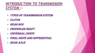
1. INTRODUCTION TO TRANSMISSION
SYSTEM :-
TYPES OF TRANSMISSION SYSTEM
CLUTCH
GEAR BOX
PROPEELER SHAFT
UNIVERSAL JOINTS
Final drive and differential
REAR AXLE
2. Definition Of Transmission System :-
The mechanism that transmits the power developed by the engine of
automobile to the engine to the driving wheels is called the
TRANSMISSION SYSTEM (or POWER TRAIN).It is composed of –
Clutch
The gear box
Propeller shaft
Universal joints
Rear axle
Wheel
Tyres
3. Requirements Of Transmission System :-
Provide means of connection and disconnection of engine with rest of
power train without shock and smoothly.
Provide a varied leverage between the engine and the drive wheels
Provide means to transfer power in opposite direction.
Enable power transmission at varied angles and varied lengths.
Enable speed reduction between engine and the drive wheels in the ratio
of 5:1.
Enable diversion of power flow at right angles.
Provide means to drive the driving wheels at different speeds when
required.
Bear the effect of torque reaction , driving thrust and braking effort
effectively.
4. The above requirements are fulfilled by the following
main units of transmission system :-
Clutch
Gear Box
Transfer Case
Propeller Shaft and Universal Joints.
Final Drive
Differential
Torque Tube
Road Wheel
5. Difference between tyre and wheel :-
Wheel Tyre
A wheel is a device that allows
heavy objects to be moved easily
through rotating on an axle
through its centre, facilitating
movement or transportation
while supporting a load (mass),or
performing labor in machine.
While tyre is the outer part of
the wheel made up with rubber
and mostly use in vehicles for
smooth movement
7. Hydraulic transmission system:-
Fluid coupling -: A fluid coupling is
a hydrodynamic device used to transmit
rotating mechanical power.It has been used in
automobile transmissions as an alternative to
a mechanical clutch.
8. How fluid coupling can be act as a
mechanical clutch ?
o In automotive applications, the pump typically is
connected to the flywheel of the engine The turbine is
connected to the input shaft of the transmission. While
the transmission is in gear, as engine speed
increases torque is transferred from the engine to the
input shaft by the motion of the fluid, propelling the
vehicle . So, the behavior of the fluid coupling strongly
resembles that of a mechanical clutch driving a manual
transmission.
9. Construction Of a Fluid Coupling :-
It consists of a pump-generally known as impeller and
a turbine generally known as rotor, both enclosed
suitably in a casing . They face each other with an air
gap. The impeller is suitably connected to the prime
mover while the rotor has a shaft bolted to it. This
shaft is further connected to the driven machine
through a suitable arrangement. Oil is filled in the
fluid coupling from the filling plug provided on its
body.
10. Operating principle of fluid coupling :-
There is no mechanical interconnection between the impeller and the rotor and
the power is transmitted by virtue of the fluid filled in the coupling. The
impeller when rotated by the prime mover imparts velocity and energy to the
fluid, which is converted into mechanical energy in the rotor thus rotating it. The
fluid follows a closed circuit of flow from impeller to rotor through the air gap at
the outer periphery and from rotor to impeller again through the air gap at the
inner periphery. To enable the fluid to flow from impeller to rotor it is essential
that there is difference in the "heat" between the two and thus it is essential
that there is difference in R.P.M., known as slip between the two. As the slip
increases more and more fluid can be transferred from the impeller to the rotor
and more torque is transmitted.
11. Torque Converter :- Torque converter is a hydraulic transmission which increases
the torque of the vehicle reducing its speed . It provides a continuous variation of
ratio from low to high. The key characteristic of a torque converter is its ability to
multiply torque when there is a substantial difference between input and output
rotational speed, thus providing the equivalent of a reduction gear. cars with
an automatic transmission have no clutch that disconnects the transmission from
the engine. So, they use an amazing device called a torque converter.
Torque converter:-
12. What’s Inside The Torque Converter?
There are four components inside the very strong housing of the torque converter:
Pump
Turbine
Stator
Transmission fluid
These are the parts in the figure turbine,stator,pump
(left to right).
The housing of the torque converter is bolted to the flywheel of the engine, so it turns at
whatever speed the engine is running at. The pump inside a torque converter is a type of
centrifugal pump. As it spins, fluid is flung to the outside. As fluid is flung to the outside, a
vacuum is created that draws more fluid in at the center. The fluid then enters the blades of
the turbine, which is connected to the transmission. The turbine causes the transmission to spin,
which basically moves your car. The blades of the turbine are curved. This means that the fluid,
which enters the turbine from the outside, has to change direction before it exits the center of
the turbine. It is this directional change that causes the turbine to spin.
13. In order to change the direction of a moving object, you must apply a
force to that object -- it doesn't matter if the object is a car or a drop of
fluid. And whatever applies the force that causes the object to turn must
also feel that force, but in the opposite direction. So as the turbine
causes the fluid to change direction, the fluid causes the turbine to spin.
The fluid exits the turbine at the center, moving in a different direction
than when it entered.The fluid exits the turbine moving opposite the
direction that the pump (and engine) are turning. If the fluid were
allowed to hit the pump, it would slow the engine down, wasting
power. This is why a torque converter has a stator.The stator resides
in the very center of the torque converter. Its job is to redirect the
fluid returning from the turbine before it hits the pump again. This
dramatically increases the efficiency of the torque converter. The
stator has a very aggressive blade design that almost completely
reverses the direction of the fluid. A one-way clutch (inside the
stator) connects the stator to a fixed shaft in the transmission (the
direction that the clutch allows the stator to spin is noted in the
figure above). Because of this arrangement, the stator cannot spin
with the fluid -- it can spin only in the opposite direction, forcing the
fluid to change direction as it hits the stator blades.
The figure (top to bottom) shows the pump,turbine and the stator,
sending the fluid in their respective direction.
14. Intersting facts about stator !!!
Something a little bit tricky happens when the car gets moving.
There is a point, around 40 mph (64 kph), at which both the pump
and the turbine are spinning at almost the same speed (the pump
always spins slightly faster). At this point, the fluid returns from
the turbine, entering the pump already moving in the same
direction as the pump, so the stator is not needed.
Even though the turbine changes the direction of the fluid and
flings it out the back, the fluid still ends up moving in the
direction that the turbine is spinning because the turbine is
spinning faster in one direction than the fluid is being pumped in
the other direction. If you were standing in the back of a pickup
moving at 60 mph, and you threw a ball out the back of that
pickup at 40 mph, the ball would still be going forward at 20 mph.
This is similar to what happens in the turbine: The fluid is being
flung out the back in one direction, but not as fast as it was going
to start with in the other direction.
15. Manual transmission system :-
In this type of transmission system , the driver has to manually select and
engage the gear ratios -:
Clutch fully
depressed The clutch is fully disengaged when the pedal is fully depressed. There will be no torque
being transferred from the engine to the transmission and wheels. Fully depressing the
clutch allows the driver to change gears or stop the vehicle.
Clutch slips
The clutch slips is the point that vary between being fully depressed and released. The
clutch slip is used to start the vehicle from a stand still. It then allows the engine rotation
to adjust to the newly selected gear ratio gradually . It is recommended not to slip the
clutch for a long time because a lot of heat is generated resulting in energy wastage.
Clutch fully
realeased
The clutch is fully engaged when the pedal is fully released. All the engine torque will be
transmitted to the transmission. This results in the power being transmitted to the wheels
with minimum loss.
Stages of Manual transmission
16. Automatic transmission :-
Automatic transmission system is the most advanced system in
which drives mechanical efforts are reduced very much and
different speeds are obtained automatically. This system is
generally also called hydramatic transmission. It contain epicyclic
gear arrangement, fluid coupling and torque converter. In this
planetary gears sets are placed in series to provide transmission.
This type of transmission are used by Skoda ,Toyota , Lexus , etc
Epicyclic gearing (planetry gearing) :- it is a gear
system consisting of one or more outer gears, or planet gears,
revolving about a central gear .By using epicyclic gear , different
torque speed ratio can be obtained . It also compact the size of
gear box.
17. Stages of automatic transmission :-
Park(P) :- selecting the park mode will lock the transmission, thus restricting the vehicle
from moving.
Reverse( R) :- selecting the reverse mode puts the car into reverse gear, allowing the
vehicle to move backward.
Neutral (N) :- selecting neutral mode disconnects the transmission from the wheel.
Low (L) :- selecting the low mode will allow you to lower the speed to move on hilly and
middy areas.
Drive (D) :- selecting drive mode allows the vehicle to move and accelerate through a range
of gears.
18. Comparison between manual transmission
and automatic transmission :-
Manual transmission Automatic transmission
Vehicles with manual transmission are
usually cheaper .
Vehicles with automatic transmission are
costlier than those of manual
transmission.
Manual transmission has better fuel
economy . This is because manual
transmission has better mechanical and
gear train efficiency.
Automatic transmission has not better
fuel economy . This is because automatic
transmission has not better mechanical
and gear train efficiency as compare to
those of automatic transmission.
Manual transmission offers the driver
more control of the vehicle.
Automatic transmission does not offer the
driver more control of the vehicle as
compare to that of automatic
transmission system.
19. CLUTCH
A clutch is a mechanism which enables the rotary motion of one shaft to be transmitted at
will to second shaft ,whose axis is coincident with that of first.
Clutch is located between engine and gear box. When the clutch is engaged, the power
flows from the engine to the rear wheels through the transmission system and the vehicle
moves . when the clutch is disengaged ,the power is not transmitted to the rear wheels and
the vehicle stops, while the engine is still running.
Clutch is disengaged when-
a) Starting the engine,
b) Shifting the gears,
c) Idling the engine
clutch is engaged only when the vehicle is to move and is kept engaged when the vehicle is
moving.
20. Function Of a Clutch :-
a) To permit engagement or disengagement of a gear when the vehicle is stationary and the
engine is running
b) To transmit the engine power to the road wheels smoothly without shock to the transmission
system while setting the wheel in motion.
c) To permit the engaging of gears when the vehicle is in motion without damaging the gear
wheels.
Principle Of Operation Of a Clutch :-
The clutch principle is based on friction . when two friction surface are brought in contact
with each other and pressed they are united due to friction between them. If one is revolved
the other will also revolve . The friction between the two surfaces depends upon-
i. Area of the surface,
ii. Pressure applied upon them,
iii. Coefficient of friction of the surface materials
Here , One surface is considered as driving member and the other as driven member.
21. The driving member of a clutch is the flywheel mounted on the crankshaft, the
driven member is the pressure plate mounted on the transmission shaft .
Friction surfaces (clutch plates ) are between the two members (driving and
driven). On the engagement of the clutch, the engine is connected to the
transmission (gear box) and the power flows from the engine to the rear wheels
through the transmission system . when the clutch is disengaged by pressing a
clutch pedal, the engine is disconnected from the transmission and consequently
the power does not flow to the rear wheels while the engine is still running.