Downloaded 281 times


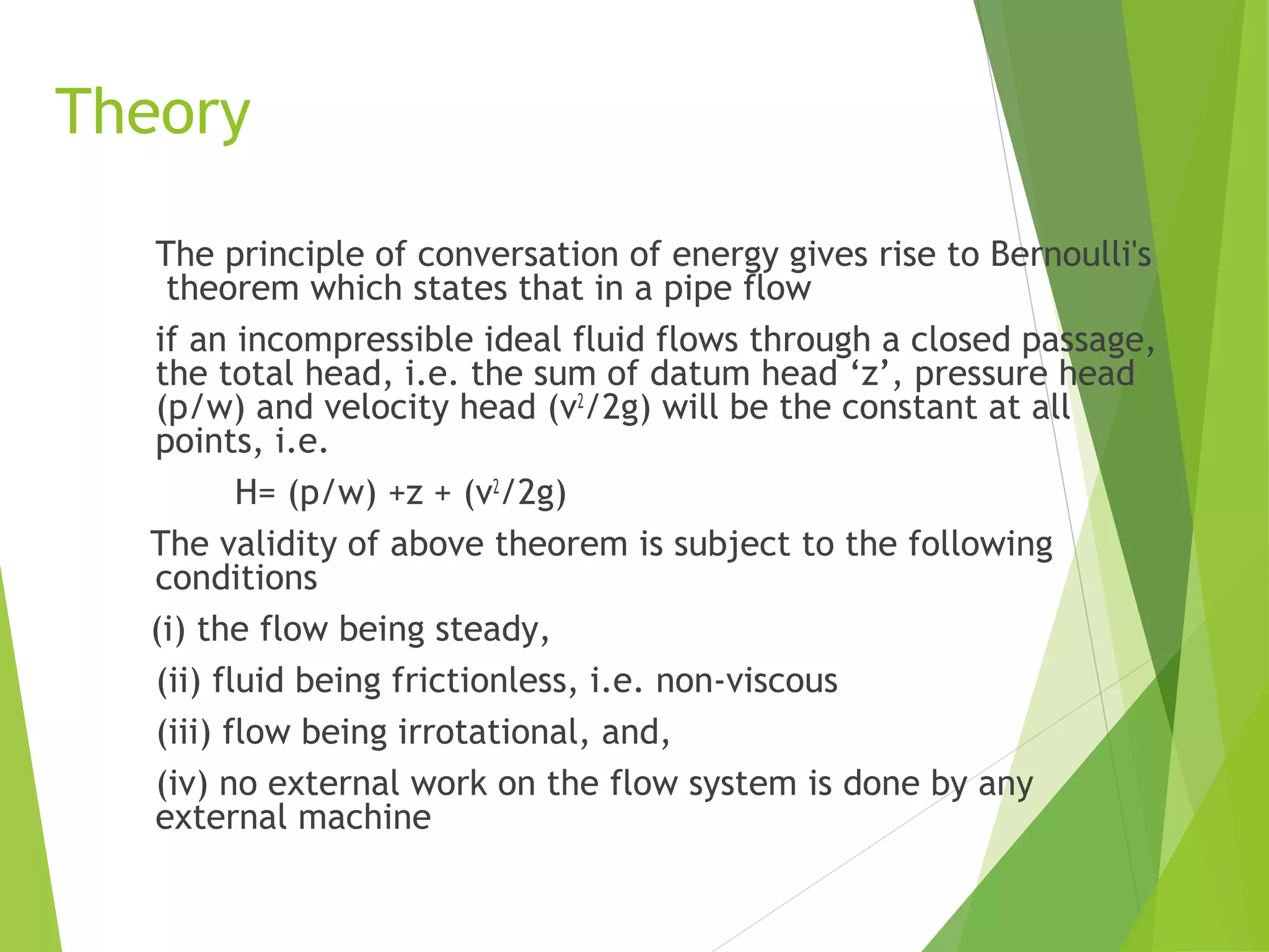

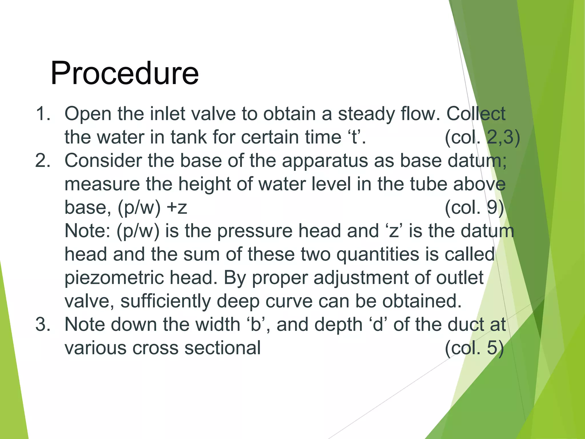
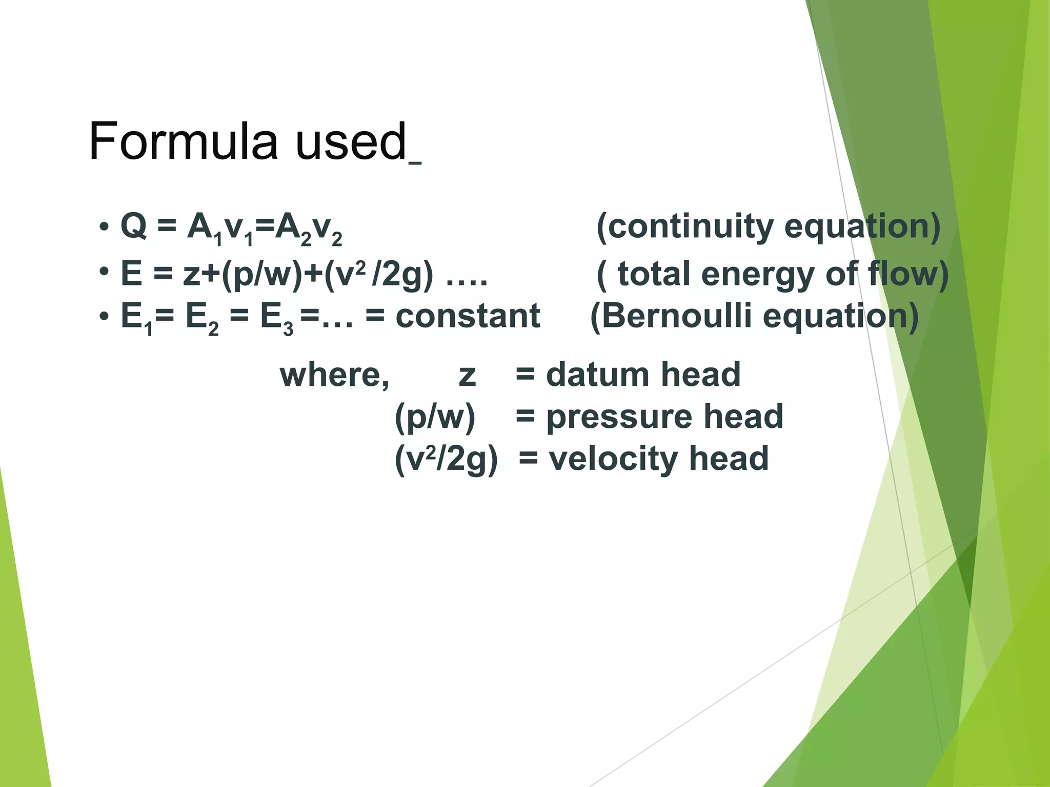
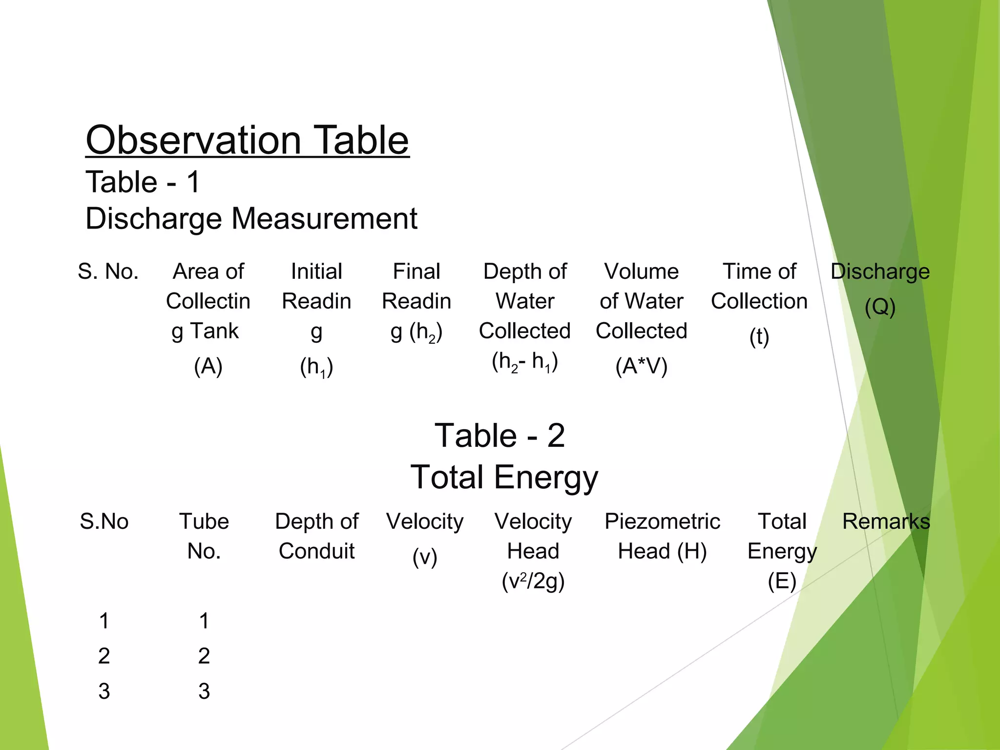
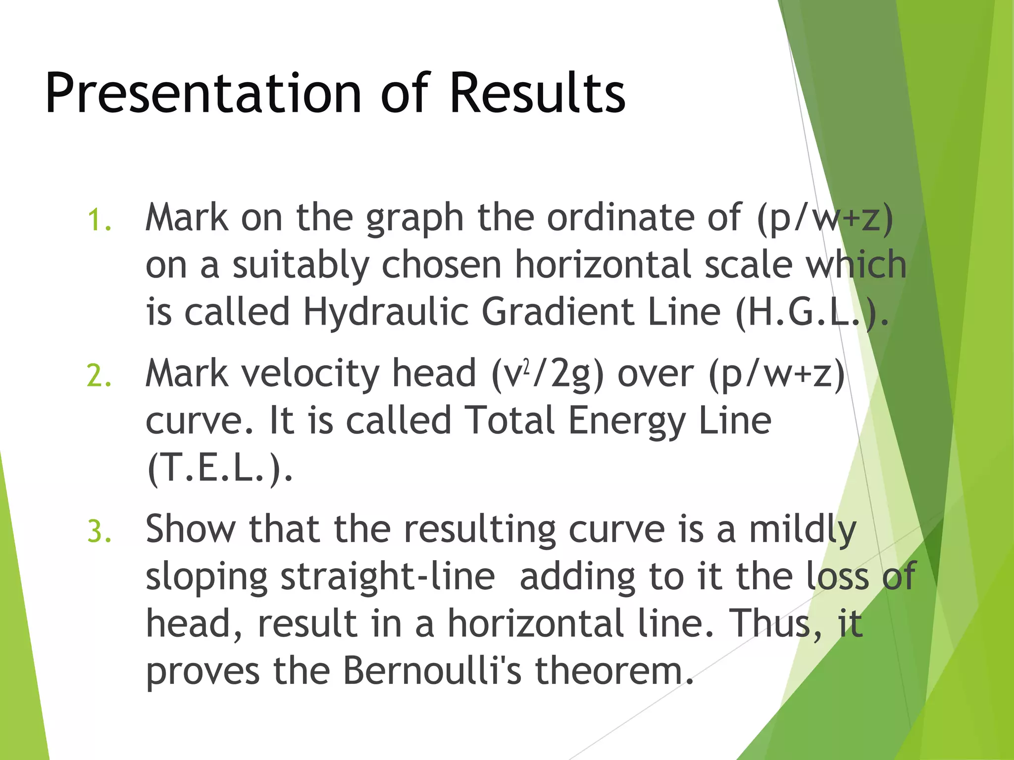

This document describes an experiment to verify Bernoulli's theorem. Bernoulli's theorem states that for an inviscid, incompressible fluid flowing steadily through a closed passage, the total energy at any point remains constant. The experiment involves measuring the pressure, velocity, and elevation at different points in a diverging duct carrying water. Observations are recorded and used to plot the total energy line, which should be horizontal according to Bernoulli's theorem. The results support the theorem by showing the total energy remains constant despite changes in pressure, velocity, and elevation along the duct.


![Unit -2b Fluid Dynamics [Compatibility Mode].pdf](https://cdn.slidesharecdn.com/ss_thumbnails/unit-2bfluiddynamicscompatibilitymode-240912163512-a36cdd14-thumbnail.jpg?width=640&height=640&fit=bounds)


![Coded Agents – with UiPath SDK + LangGraph [Virtual Hands-on Workshop]](https://cdn.slidesharecdn.com/ss_thumbnails/codedagentsdeck-251215155422-5497c599-thumbnail.jpg?width=640&height=640&fit=bounds)


