
Downloaded 206 times

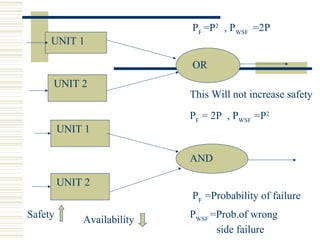

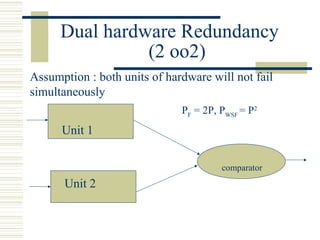
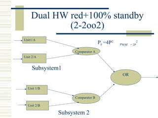

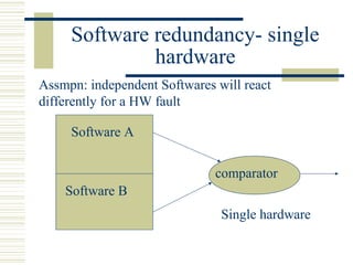
This document discusses safety concepts and practices in railway signalling. It covers fail-safe principles, redundancy techniques, and self-check methods used to ensure safety in signalling systems. The key points are: 1) Signalling systems are designed to be fail-safe, meaning any failure will result in a safe reaction by defaulting to the lowest energy state. This is achieved through mechanical and electrical designs. 2) Microprocessors are not inherently fail-safe, so redundancy and self-checks are used to monitor for faults and ensure safe operation. Techniques include dual hardware, triple modular redundancy, and watchdog timers. 3) Railway interlocking systems are designed so that running signals cannot be lowered unless routes are set


