
Downloaded 194 times


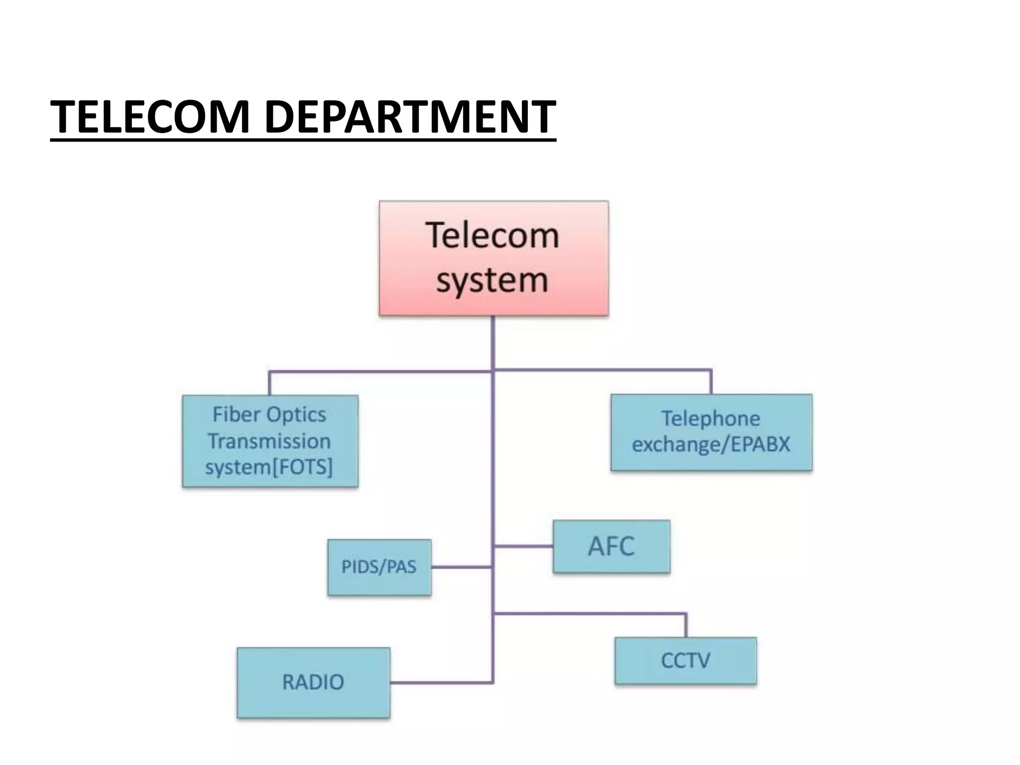

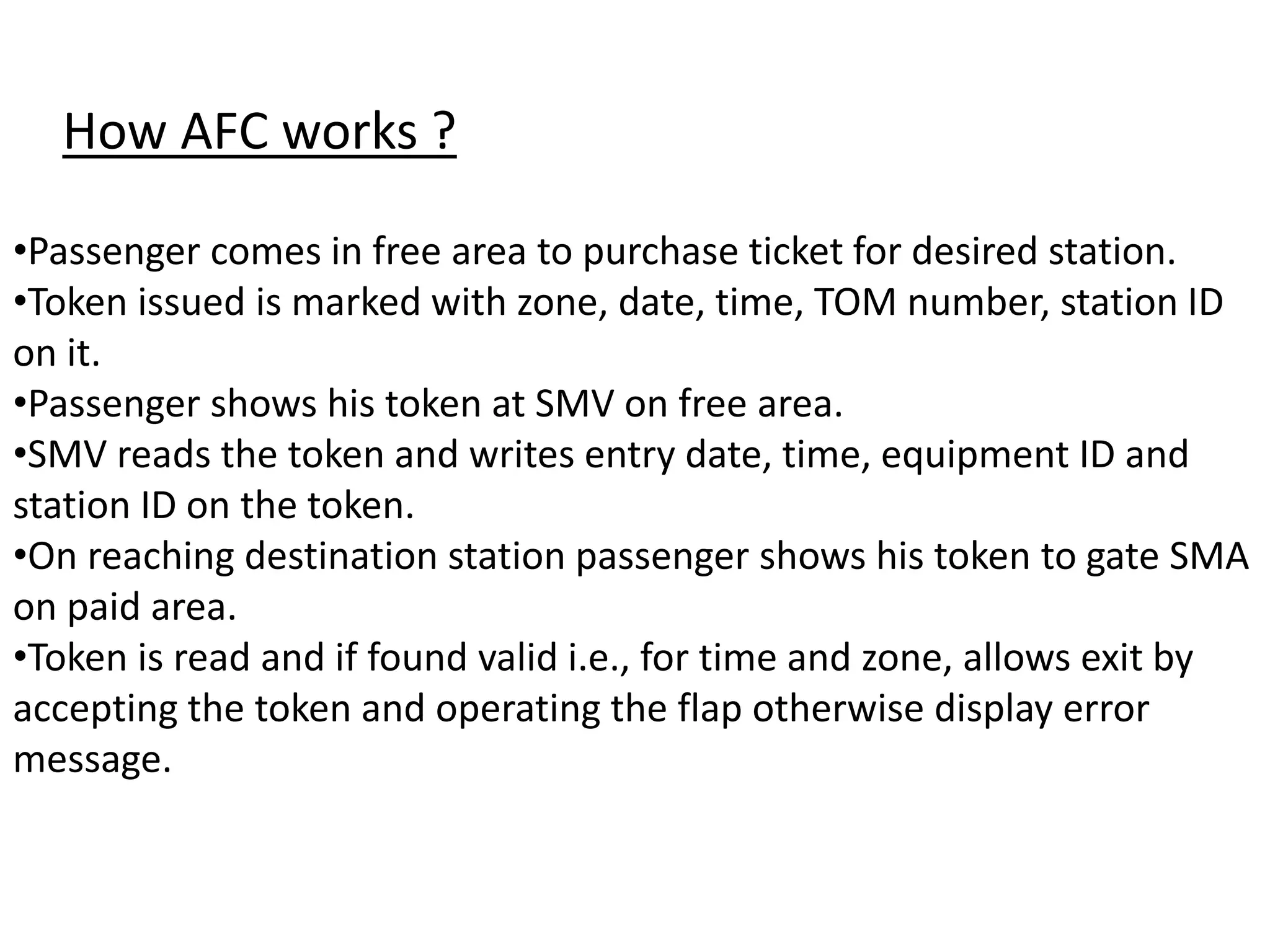


The document provides an overview of the Delhi Metro Rail Corporation (DMRC) and its telecom department, detailing the automatic fare collection (AFC) system which automates the ticketing process for public transportation. It explains the components and functionalities of the AFC system, including automatic gates, ticket vending machines, and station computers, along with telecom systems such as public information displays and public address systems. Additionally, it describes the technical specifications and operational aspects of various devices used for communication and ticketing at DMRC stations.


