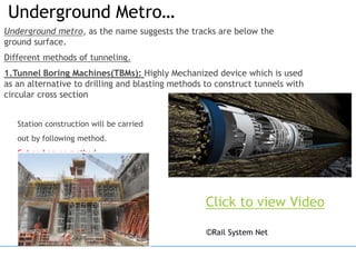
2. Metro?
Metro is the most common term for underground rapid
transit systems used by non-native
Rapid transit or mass rapid transit (MRT), is a type of
high-capacity public transport generally found in urban
areas.
Unlike buses or trams, rapid transit systems are electric
railways that operate on an exclusive right-of-way,
which cannot be accessed by pedestrians or other
vehicles of any sort,and which is often grade-separated
in tunnels or on elevated railways.
China has the largest number of rapid transit systems in
the world
Somewhere in INDIA…
3. Why do you need a Metro?
To decongest the city…. Then why not go with Elevated one’s?
Under construction elevated metro….
Somewhere in INDIA…
4. To Start with….!
Rapid transit or mass rapid transit (MRT), also known as heavy rail, Metro, subway or
tube is a type of high-capacity public transport generally found in Metropolitan
cities/urban areas. Unlike buses or trams, rapid transit systems are electric railways
that operate on an exclusive right-of-way, which cannot be accessed by pedestrians
or other vehicles of any sort, and which is often grade separated in tunnels or on
elevated railways.
5. DIFFERENT TYPES OF METRO
There are three types of metro
stations
Underground metro
At-Grade metro
Elevated metro
6. Most of viaduct structures are being constructed using pre-cast segments
installed using the underslung girder technique.
The advantage of this technique is that it enables the viaduct deck spans
to be erected very rapidly on site with minimal disruption to traffic below.
Viaducts are essentially multi-spanned bridges crossing over roads or
rivers or valleys.
ELEVATED METRO
8. A passenger railway going inside an urban area was called the
METROPOLITAN RAILWAY (urban train system), in modern English: METRO
“Underground Metros were ideal but could not be executed in the city due
to several, particularly financial, constraints.”- Mumbai Metro Rail
Corporation’s (MMRC) Ex-managing director, Ashwini Bhide.
Bhide said the ideal situation could
be that all Metro lines are
underground. But for a country and
a city like ours, where we have a
huge resource crunch, we have tried
to find a solution
Underground METRO
10. 2. New Austrian Tunnelling method(NATM):
Modern Tunnel construction methods where the surrounding rock or soil
formation of a tunnel is integrated into an overall ring like support
structure.
Underground Metro… contd…
22. PURPOSE OF STATION VAC
Typically, underground stations are interspaced at 1 km.
Heat is generated by Traction and other equipment.
Today's state-of-art modern-rolling stock provided with air-
conditioners dissipates substantial heat inside the subway
resulting in the hot air in the tunnel and pulsating heat load on the
platform along with the train.
In an underground section, a Large number of Patrons are
Confined in an Enclosed Space
Supply of fresh air to patrons for biological need
Removal of latent body heat, obnoxious and harmful gases
Removal of sensible heat and fumes from batteries, UPS, lights
etc.
23. VAC – VENTILATION & AIR-CONDITIONING SYSTEM
Consists of
Air Conditioning of UG Stations
Mechanical Ventilation for Plant
Rooms
Smoke Control and Extraction
24. ECS SYSTEM EQUIPMENT
Chillers
Chilled and Condenser Water pumps
Cooling Towers
Air Handling Units
Fan Coil Units
Fresh Air Fans
Ventilation Supply/Exhaust Fans
Smoke Extract Fans
Staircase Pressurization Fans
27. Some stations consists of three or more levels. Plant room for the station is located
generally in Ancillary Building / intermediate level/ other level along with pump room.
Two AHU Rooms Located on either end of the station are generally at the
concourse level meant for the purpose of Air Conditioning of public areas and
entrances. Individual Rooms will be air-conditioned by FCUs. The bifurcation of the
rooms on each level is generally as below.
• Paid and Unpaid Public Areas
• AHU Rooms, Station Control Room,
SCADA,Ventilation Fans , SER, TER, Ticket
Office
• Toilets, Train Captain & Crew Rooms , Retail
areas etc
Concourse Level
• UtilityRoom, Water Tank, Pump Room,
Electrical Room.
• Subways
Intermediate
Level
• Public Area , ASS, Electrical Room
• UPS, Telecom Room etc.
Platform Level
28. 12/5/2020
CENTRAL PLANT AIR-CONDITIONING SYSTEM
Condenser
Pump Cooling
Tower
Condenser
Chillers
A
H
U
36°C
30°C
Condenser
Water Line
Motor
Compressor Expansion VLV
8°C
15°C
Chiller Pump
Liquid Refrigerant Line Chilled Water Line
31. TVS – Major Design criteria
Latest ASHRAE /ISHRAE standards for ambient air conditions.
In normal mode TVS designed to maintain a maximum dry DBT of 40deg C
Congested mode – TVS designed for 45 deg C ( max ) in the tunnel .
Emergency mode ( Fire )
Heat release rate for a train shall be 15 MW
Radiant fraction of 30 % .
NFPA 130.
Heat load from train at normal and congested mode shall be around 610
kw for 6 car train .
Tunnel layouts
Braking heat loads , traction motor losses , AC loads etc
Headway.
One train between two consecutive ventilation shafts .
Pressurization of non incidental tunnels .
33. Tunnel Ventilation system – Why ??
Normal operating conditions; to provide ventilation relief from piston
effect.
Congested operation; to provide air flow inside tunnel to control temp.
rise.
Emergency scenario of fire;
to extract smoke from tunnel and
provide safe evacuation path for the passengers
provide safe path for the fire fighters
During Non-Revenue period; to provide ventilation inside tunnel for
maintenance staff
:
34. TVS – Normal Mode
Piston effect of
running trains
Ventilation in
Normal Mode
Track way
Ventilation system
“ Normal Mode - When trains are working to
timetable throughout the system, at
prescribed headways and dwell times, within
given tolerances.”
Track way exhaust systems
Over track exhaust system
Under platform supply system
OTE ducts
36. TVS – Normal Mode
LOW TEMPERATURE HIGH TEMPERATURE
PISTON EFFECT
STATION1 STATION2
LOW TEMPERATURE HIGH TEMPERATURE
PISTON EFFECT
STATION1 STATION2
NORMAL SCENARIO
37. TVS – Congested Mode
Tunnel
Ventilation fans (
Piston effect zero
) )
Congested
Mode
Track way Ventilation
system
Congested mode – Any deviation from the
Normal operation ( expect from emergency
situations ) . TVS systems ‘ congested mode’
operation to provide air flow inside tunnel to
control temperature rise .
Over track exhaust system
Under platform supply system
OTE ducts
Tunnel Ventilation fans
38. TVS – Congested Mode
Draught relief dampers closed .
TVF are in operation .
TEF / UPS fans running as required .
39. TVS – Congested Mode
LOW TEMPERATURE HIGH TEMPERATURE
PISTON EFFECT
STATION1 STATION2
LOW TEMPERATURE HIGH TEMPERATURE
PUSH - PULL VENTILATION
STATION1 STATION2
‘CONGESTION SCENARIO’
40. TVS – Emergency ( In tunnel )
Tunnel Ventilation fans Emergency
Mode
Emergency
To extract smoke from tunnel
Provide safe evacuation for the
passengers
Provide safe path for the fire fighters
41. TVS – Emergency Mode ( Tunnel )
Click here – TVS ( Full layout )
42. TVS – Emergency Mode ( Cross over )
Pressurization in the adjacent tunnels for safe evacuation of passengers .
43. TVS – Fire in Track way
* With smoke exhaust off
* With smoke exhaust on
44. TVS – Fire in Track way
LOW TEMPERATURE HIGH TEMPERATURE
PISTON EFFECT
STATION1 STATION2
LOW TEMPERATURE HIGH TEMPERATURE
PUSH - PULL VENTILATION
STATION1 STATION2
FIRE EMERGENCY SCENARIO
46. Lets take an idea of Fan
sizes.
Tunnel ventilation fans, classically, must have the ability to
both supply and extract air from a tunnel system, with the
operator's choice dependent on the tunnel ventilation
system's operating mode most appropriate at any given
point in time. Consequently, tunnel ventilation fans must
incorporate a reversible aerodynamic design which limits
the maximum fan pressure rise.
These fans range from 1.4 m dia to 2+ m dia as per
requirement. Motor kW ranging from 45 kW- 300 kW.
https://youtu.be/Ae-awmqLBt0
Video Courtesy : Mr. Fathi Tarada.
12/5/202
0
53. Types of tunnel ventilation system
Longitudinal Ventilation
Here the direction of airflow is longitudinal in nature. At the
beginning of the tunnel or the tunnel section starting, these
moves the pollutant gasses and effluents, that is followed by
the fresh air. Then at the end of the tunnel portal or at the
tunnel section end, the polluted air is discharged.
The configuration of
longitudinal ventilation can
be either portal to portal,
shaft to shaft or from portal
to shaft. For transit and rail
tunnel, the longitudinal
airfow system is used.
54. Types of tunnel ventilation system
Transverse AirHow Ventilation Systems
Here uniform distribution of fresh air is created
along the length of the tunnel. It is mainly
employed in road tunnels. Occasional used for
transit tunnels. A consistent level of temperature
and the pollutants will be maintained if this system
is employed. The system can be either fully or
semi-transverse.
Transverse or semi-transverse ventilation tunnel is
better than a longitudinal one for the tunnels that
are longer than 4 to 5 km.
55. Types of tunnel ventilation system
Natural Ventilation Systems in Tunnel
When from one portal to next portal of the tunnel, there is a provision
of drift, it forms a fair ventilation during the operations involving
enlarging. This is when the tunnel length is short. In the case of long
tunnels, such natural ventilation will be inadequate and we design
separate mechanical ventilation system.
The natural ventilation
can be confgured from
portal to portal, shaft to
shaft or from portal to
shaft. The road tunnel has
an air velocity that is
uniform. The temperature
and the pollutant level
increases at the exit
portal or the section end.
56. TENABLE ENVIRONMENT DURING EMERGENCY MODE
Air temp. < 60o C
Noise < 92 dBA
Visibility up to 110 meter
CO Concentration < 1500 ppm
Radiation Heat flow < 2.5 kW/m2
Maximum Air Velocity < 11 m/s
57. EMERGENCY OPERATION
As per NFPA -130 section 7.2.1; the emergency ventilation system shall be
designed to do the following
Provide a tenable environment along the path of egress from a fire incident in
enclosed train ways
Produce airflow rates sufficient to prevent back layering of smoke in the egress
within enclosed train ways.
Be capable of reaching full operational mode within 180 Secs.
Accommodate maximum number of trains between ventilation shafts during
emergency.
58. ‘NFPA - 130 STANDARD
(FIXED GUIDE WAY TRANSIT SYSTEM)
Ventilation should meet the critical velocity requirement.
Evacuation should be in tenable environment.
Patrons shall not be exposed to high temperature or air-
velocities.
max. 381 m travel for mid-shaft evacuation.
max. 244 m travel in case of cross-passages.
59. TVS OPERATING SCENARIOS
Emergency Conditions - Occurrence
Train under fire or derailment.
Report from Train Driver/Passengers
Emergency Conditions - Consequence
Passengers may expose to smoky environment
60. EMERGENCY VENTILATION DESIGN CONSIDERATION
Fire Size
- Heat Release rate per unit time (MW)
Smoke Propagation in Tunnels
Critical Air Velocity
- Minimum air velocity required to prevent back layering of smoke
61. TVS – MAJOR DESIGN ASSUMPTIONS
Design based on the following:-
One or Two train in a Ventilation Zone
Train Fire Heat release load – 15 /20 MW
TVS control shall be through SCADA from OCC
Group control of TVS plant using Modes
Semi – Automatic Control for TVS
Dual feed power supply to TVS
No passenger carrying trains at sidings, Depot Line, Link Line
62. CONTROL STRATEGY FOR TVS EQUIPMENT
1. Centrally at the OCC for entire section
Through SCADA workstation.
2. Centrally at Station Control Room for each station
Through local BMS / SCADA workstation.
3. Centrally at Station Control Room for each station
Override provision through Ventilation Control panel (VCP)
4. Locally at each PLC location for each end of station
Through Local Control Panel (LCP) of BMS
5 Locally at each TVS MCC Room
By operation of the “Manual – Off – Auto” switch at MCC room.
64. CONCLUSIONS
Thus during normal operation tunnel ventilation is achieved by piston
effect of the train
During congested or emergency mode ventilation is achieved by
running ventilation fans
Selection of technology, design and equipment provides not only
proven, reliable, but also an energy efficient system.
65. TUNNEL VENTILATION SYSTEM – Material Logistics
There must be Logistics route pre-planned
for shifting the materials. TVF fans are
weighing almost a ton.
Taking Fans from one side of the station to
other side is a challenge at concourse
level/ Mezzanine levels because of small
corridors and space constraints.
By track the materials are shifted by
trolley and pulled up through the service
cutout.
68. TUNNEL VENTILATION FLOOR MOUNTED DAMPER INSTALLATION
This is a risky job to fix damper
which is over the tunnel approx. at
6m height from track level.. At
least 600-700mm clearance is
required on each side for safe
working.
69. Service Corridor
3 to 4 different contractors
are working in same corridor
with their services at
different level. Proper co-
ordination and pre planning
is necessary.
For E&M, ECS & TVS system almost 200-250 wall cutouts and core
cutting both together are required to pass individual services (
Piping, ducting, cable tray etc.) It is recommended to prepare those
cutouts at the time of civil execution itself as it can hamper the
seismic compliance of the building at the time of manual cutting.
70. INTERFACE PLANNING & MANAGEMENT
Civil:
Finalizing of cut outs in the SEM drawings.
Interface for delivery routes/ access hatches for lowering of materials.
Interface for timely civil access for TVS, ECS & ancillary building areas.
General Lighting arrangement.
E&M:
Power, Water, Earthing for electrical panels & equipment.
Interface for the drainage points
BMS:
Interface for system requirements with E&M, Signaling, telecom, UPS,
DG, OCC.
Interface requirement for fire detection and alarm system.
Interface with signaling for OCC data transfer.
Interface with signaling for ventilation zones.