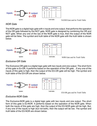
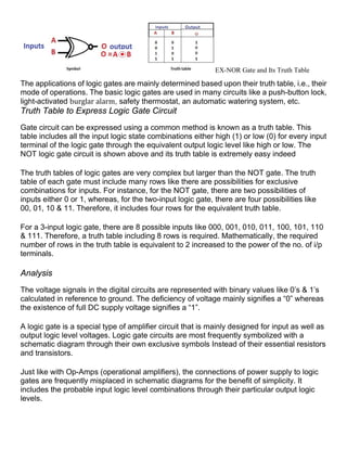
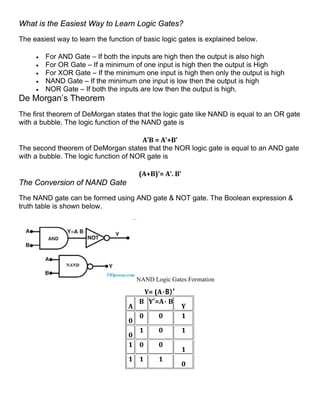
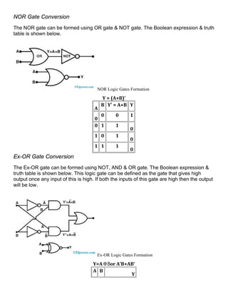
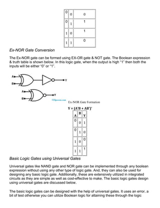
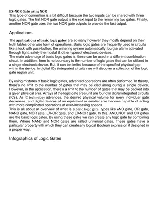
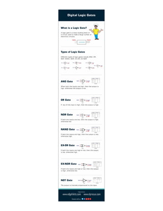
Basic Logic Gates with Truth Tables discusses the basic logic gates used in digital circuits, including AND, OR, NOT, NAND, NOR, XOR, and XNOR gates. It explains what logic gates are, how they are implemented, and provides truth tables showing the output for all possible combinations of inputs for each gate. The document is intended to provide an overview of basic logic gates and their functions using truth tables.
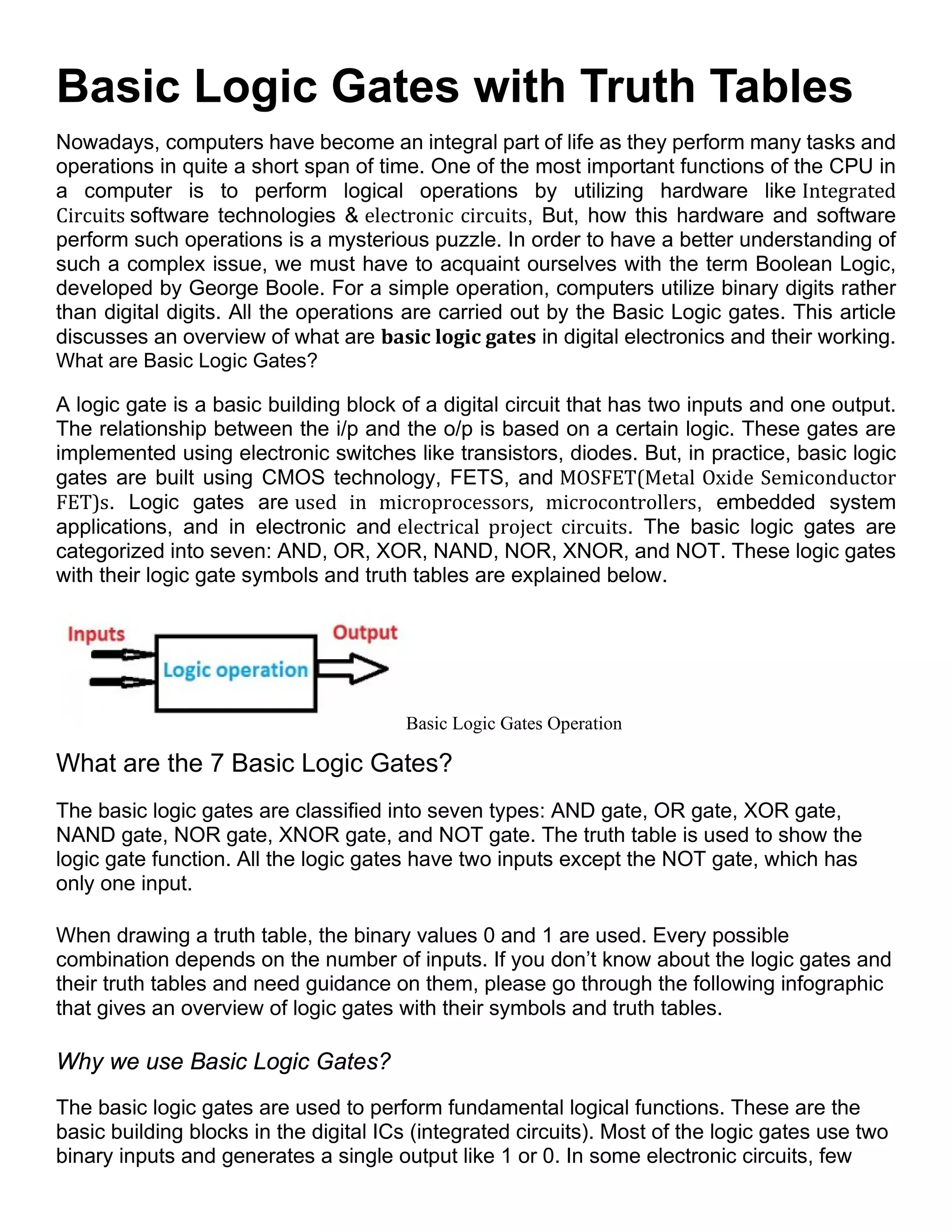


![DLD_-ASoat(41230301768)basic logic [1].pptx](https://cdn.slidesharecdn.com/ss_thumbnails/dld-asoat412303017681-251220103903-3c4281fc-thumbnail.jpg?width=640&height=640&fit=bounds)


