Download to read offline
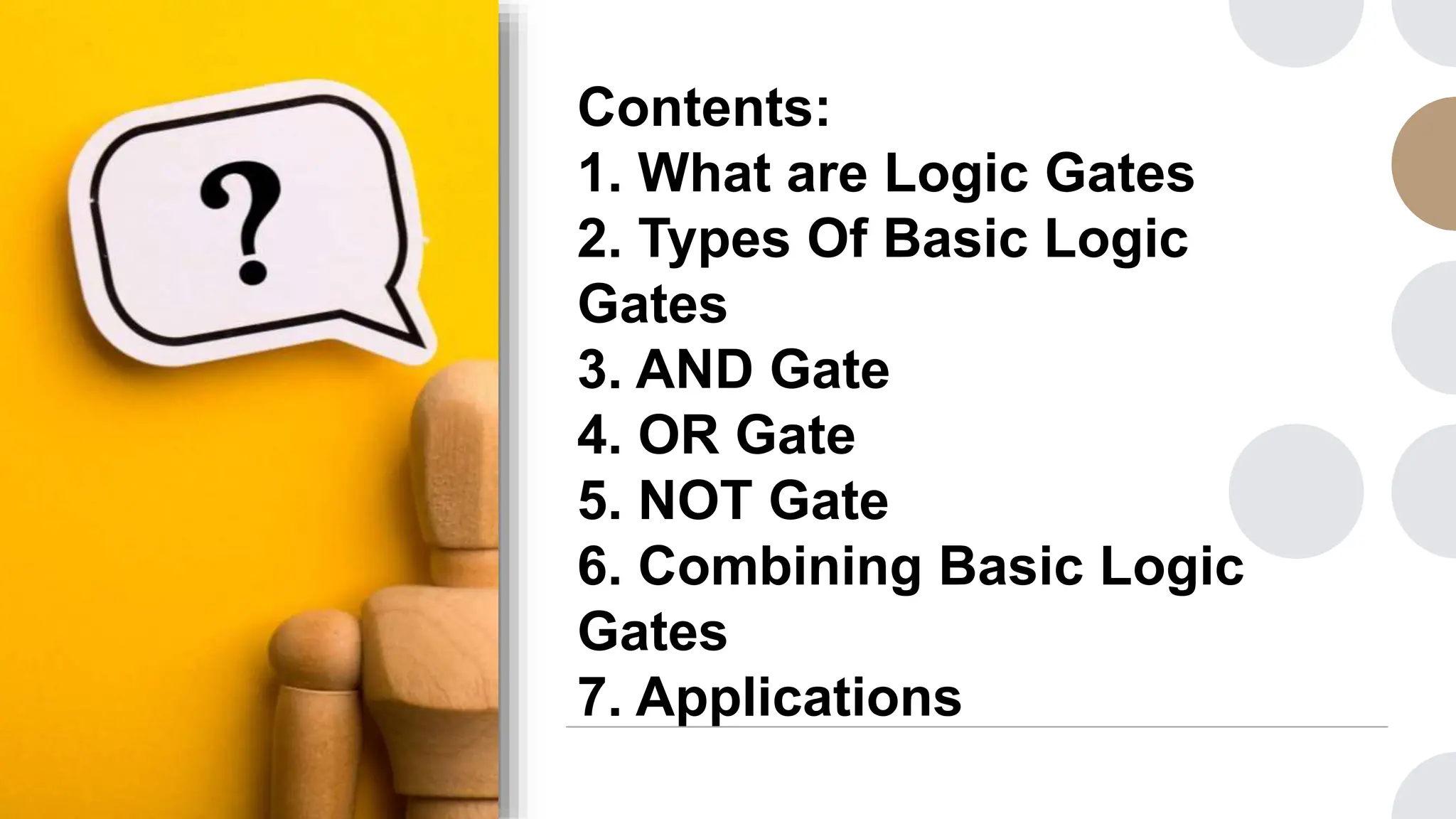
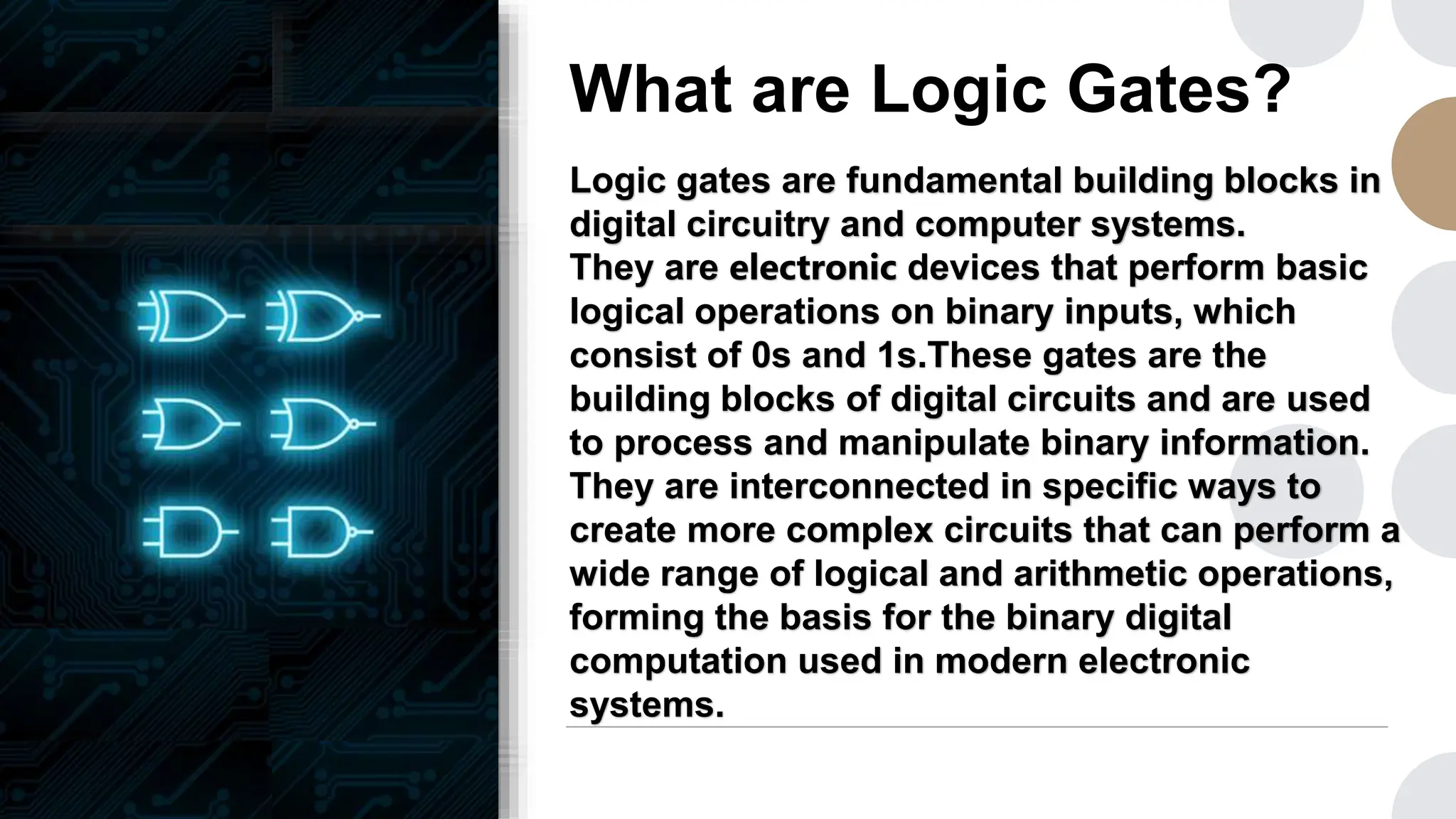
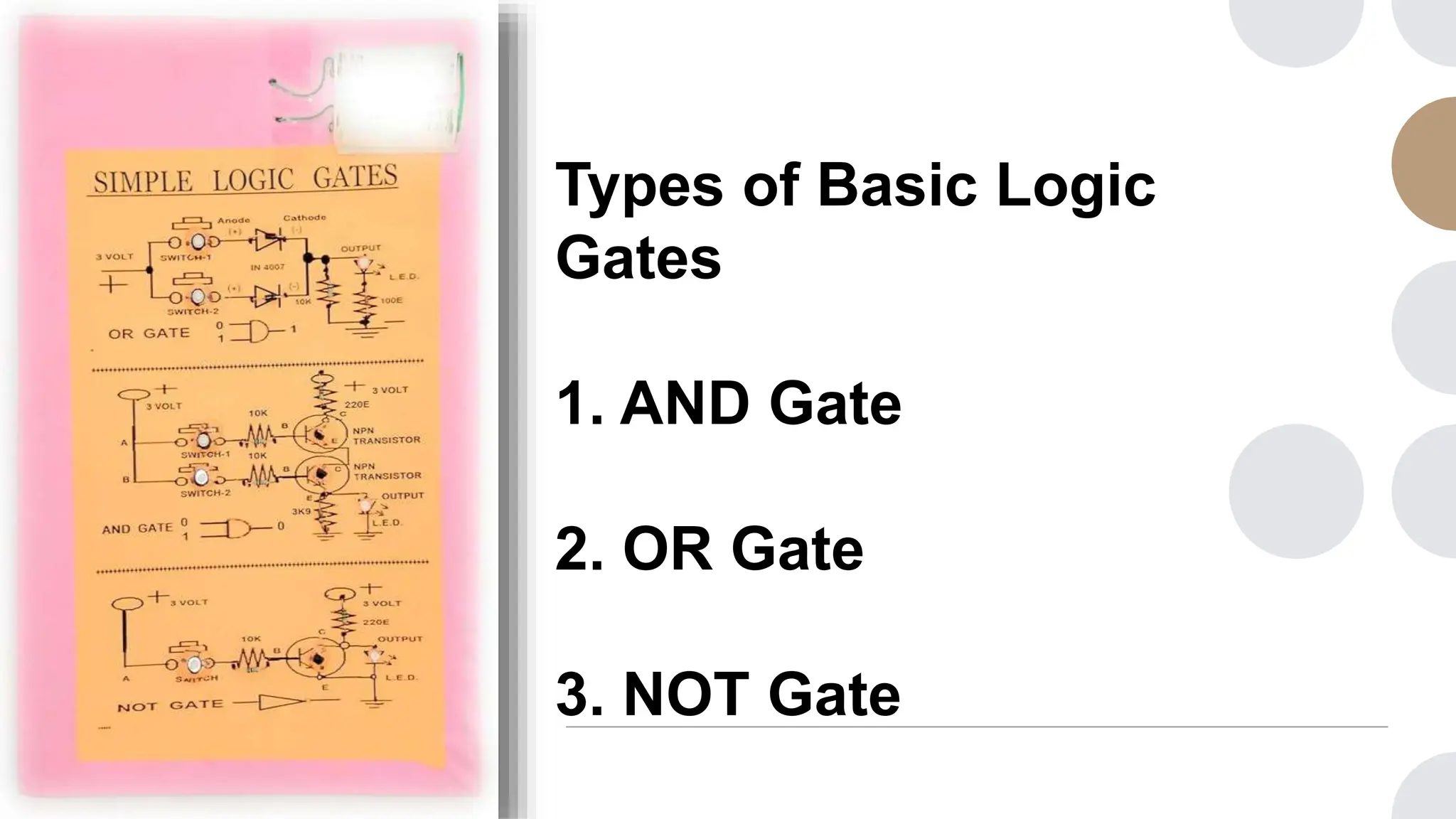
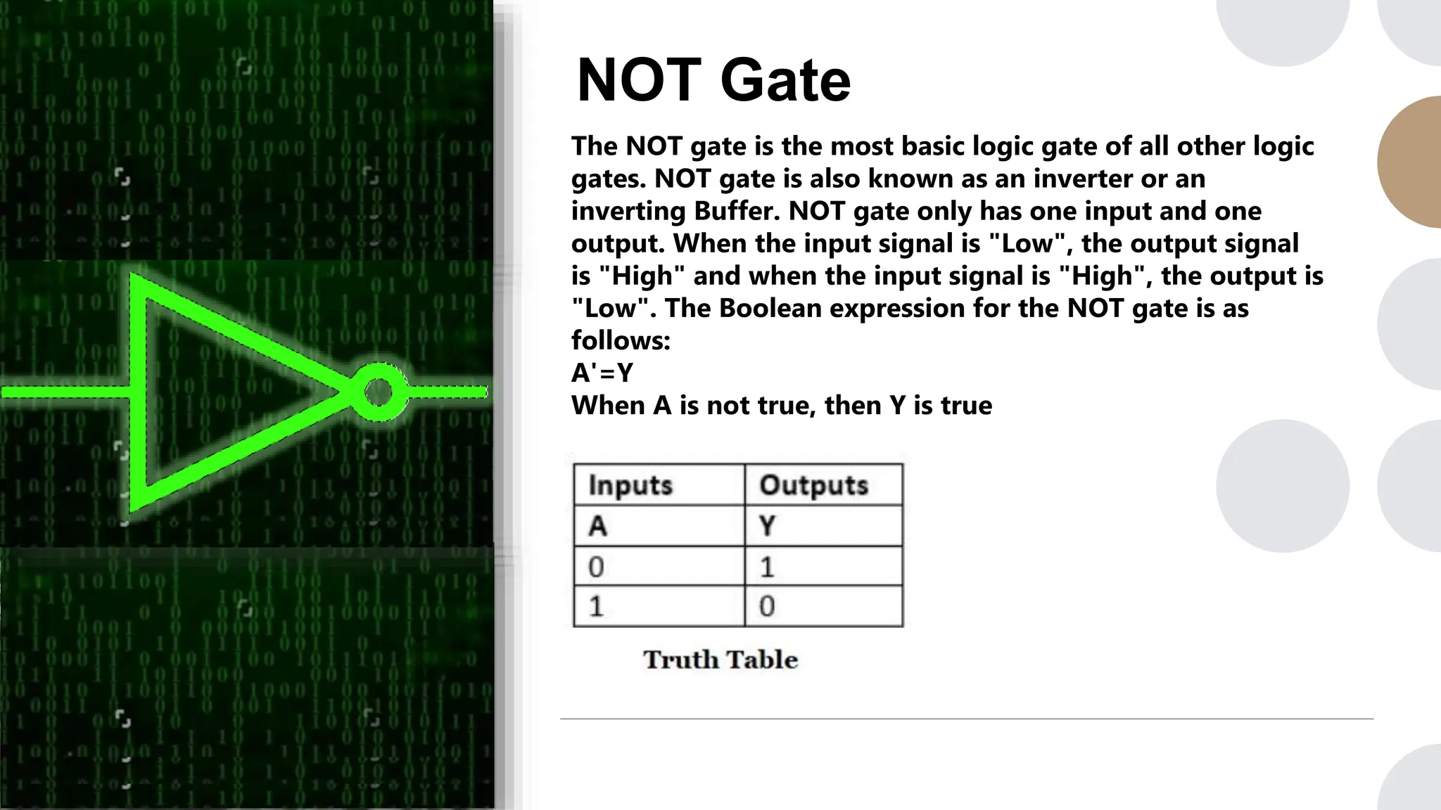
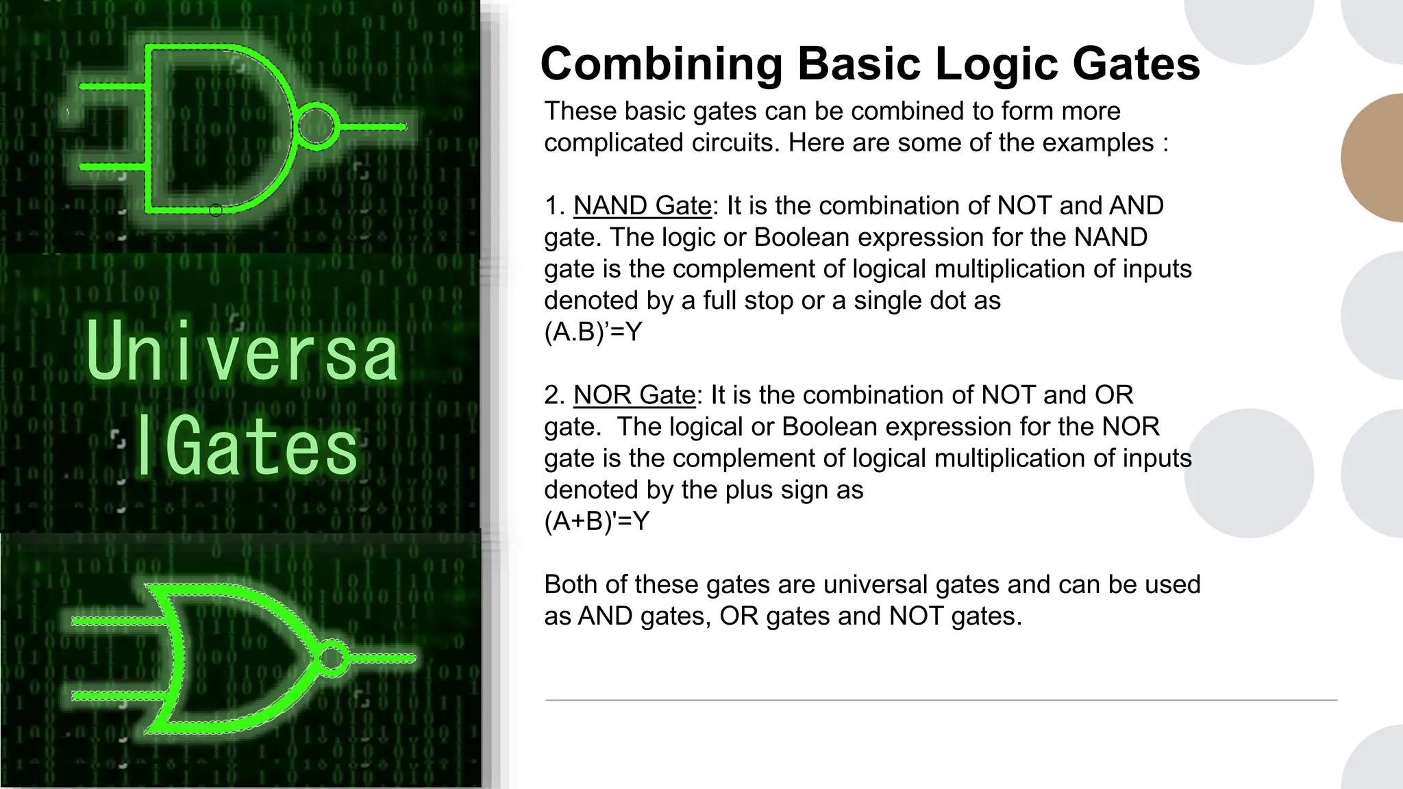
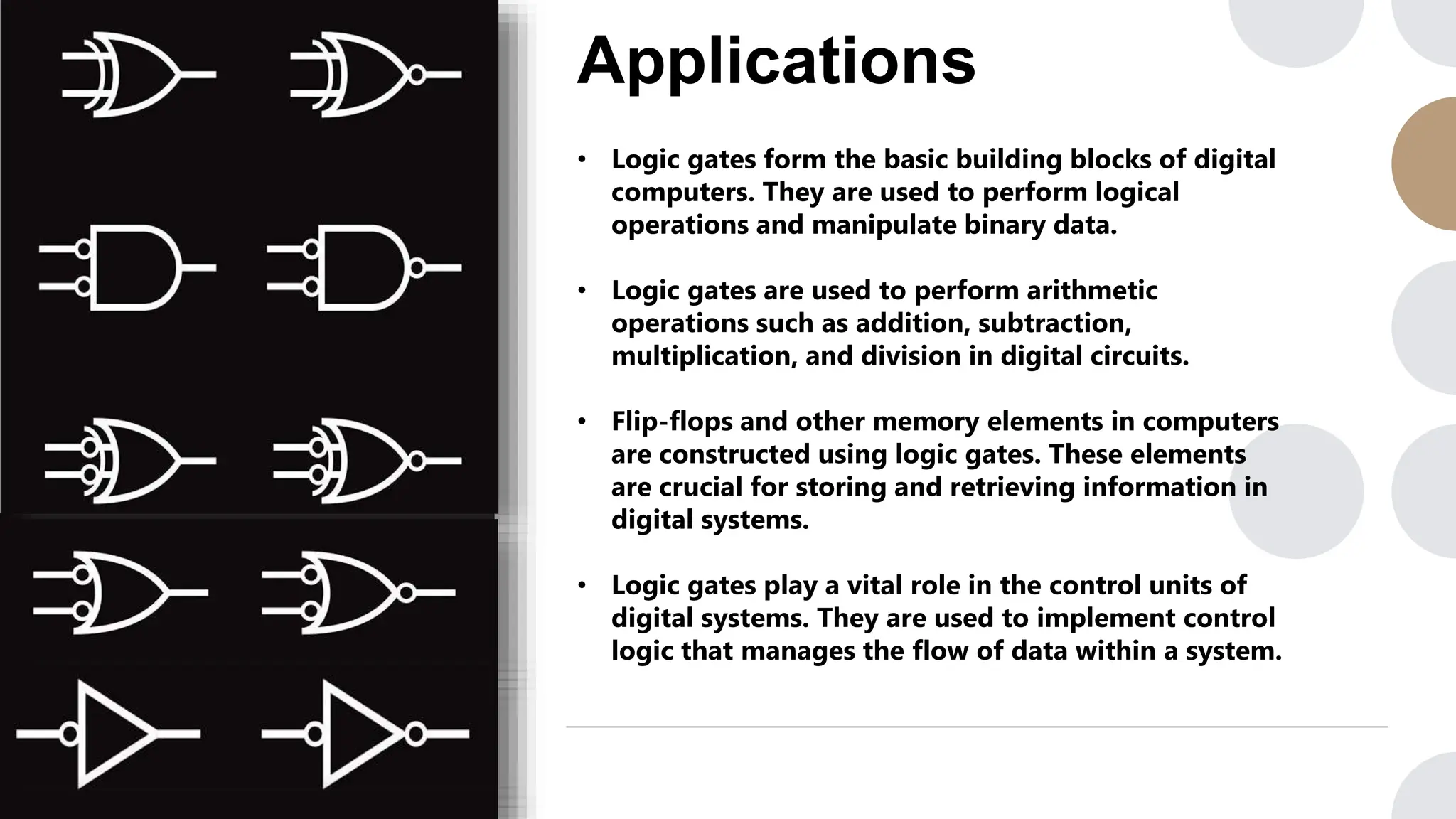


The document presents a presentation on basic logic gates, detailing their definitions, types, operations, and applications. It explains the functionality of AND, OR, and NOT gates, as well as their combinations to form more complex gates like NAND and NOR. Additionally, it highlights the essential role of logic gates in digital systems for performing logical and arithmetic operations, as well as in memory and control units.