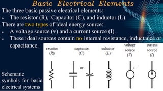
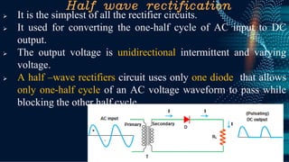
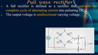
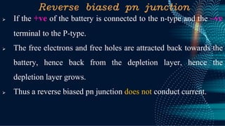
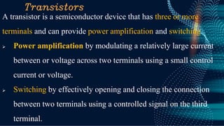
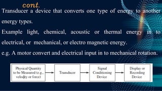
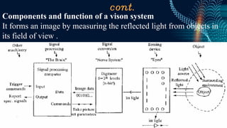
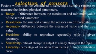
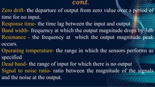
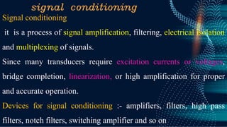
SlideShare a Scribd company logo
Introduction to Mechatronics
Department of mechanical engineering
College of engineering
Debre Berhan University
C.By Samueal T. ,2023
01
01
Introduction to Electronics,
sensors and actuators
Outline
✓ What is Electronics in Mechatronics system ?
✓ What is sensor ?
✓ What is the function of sensors and signal
conditioning?
✓ What is actuators and its function?
Basic Electrical Elements
The three basic passive electrical elements:
➢ The resistor (R), Capacitor (C), and inductor (L).
There are two types of ideal energy source:
➢ A voltage source (v) and a current source (I).
➢ These ideal sources contain no internal resistance, inductance or
capacitance.
Schematic
symbols for basic
electrical systems
Cont.
Resistors Voltage source
Capacitors Inductors
Examples of basic circuit elements
Resistor
A resistor is a dissipative element that converts electrical energy
into heat.
Ohm’s law defines an ideal resistor: V=IR , unit ohm ( ).
Conductance is the reciprocal of resistance. It is sometimes
used as an alternative to resistance to characterize a
dissipative circuit element.
Capacitor
A capacitor is a passive element that stores energy in the form of
an electric field.
Capacitor consists of a pair of parallel conducting plates separated
by a dielectric material.
The dielectric material is an insulator that increases the capacitance
as a result of permanent or induced electric dipoles in the material.
C is the capacitance
measured in farads
(F=coulombs/ volts).
I(t)=𝑪
𝒅𝒗
𝒅𝒕
Inductor
An inductor is a passive energy storage element that stores energy
in the form of a magnetic field.
The simplest form of an inductor is a wire coil, which has a
tendency to maintain a magnetic field once established.
The inductor’s characteristics are a direct result of faraday’s law of
induction. Which states
V(t)=
𝒅
𝒅𝒕
Where  is the total magnetic flux through
the coil windings due to the current.
Semi conductor devices
Electronic materials are classified in to
three type
1. Conductors
➢ Conductors have low resistance
which allows electrical current flow.
➢ Plenty of free electrons floating
➢ The atomic structure of good
conductors usually have one electron
in their outer shell.
➢ Cu, Ag, Au, Al, Ni,
Cont.
2. Insulators: have high resistance
which suppresses electrical current
flow.
Very few or no “free electrons ”
floating .
Most insulators are compound of
several elements
➢ Glass, ceramic, plastics and wood.
The atoms are tightly bound to one
another so electrons are difficult to
strip away for current flow.
Semiconductor
➢ Semiconductors are materials that
essentially can be conditioned to act
as good conductors or good
insulators, or any thing in between.
➢ semiconductor element has four
electrons in its outer or valence orbit
➢ Common elements such as carbon,
silicon, and germanium are semi
conductors.
➢ Silicon is the best and most widely used semiconductors
silicon
It has four valence electrons in its outer most shell. Which shares
with its neighboring silicon atoms to form full orbital’s of eight
electrons.
The unique capability of semiconductor atoms is their ability to
link together to form a physical structure called a crystal lattice.
Semiconductors can be insulators
❑ If the material is pure semiconductor material like silicon, the
crystal lattice structure forms an excellent insulator since all the
atoms are bound to one another and are not free for current flow.
❑ Good insulating semiconductor material is referred to as
intrinsic.
❑ Since the outer valence electrons of each atom are tightly bound
together with one another, the electrons are difficult to dislodge
for current flow.
❑ The ability conduct improved by replacing or adding certain
donor or acceptor atoms to this crystallin structure. “Doping” .
❑ Diode is a semiconductor device that allows an on way switch
for current.
semiconductors can be conductors
❑ To make the semiconductor conduct
electricity other atoms called impurities must
be added.
❑ Ex. Adding arsenic, which has 5 valence
electrons, will allow four of the arsenic
valence electrons to bond with the
neighboring silicon atoms.
❑ The one electron left over for each arsenic
atom becomes available to conduct current
flow.
❑ By controlling the doping of silicon the semiconductor material can
be made as conductive as desired.
cont.
➢ Doping a semiconductor material with
an atom such as boron that has only 3
valence electrons.
➢ The 3 electrons in the outer orbit do
form covalent bond with its
neighboring semiconductor atoms as
before.
➢ The hole assumes a positive charge so it can attract
electrons from some other source.
Types of semiconductor materials
➢ The silicon doped with extra electrons is called an “N type”
semiconductor.
“N” is for negative, which is the change of an electron.
➢ Silicon doped with material missing electrons that produce
locations called holes is called “P type” semiconductor.
“P” is for positive, which is the charge of a hole.
Cont.
N-type semiconductors doped with donor elements (e.g. arsenic or
phosphor group V elements ) that results in one additional electron
freed (free electron) from the crystal lattice as a charge carrier that
is available for conducting.
P-type semiconductors doped with acceptor elements (e.g. boron or
gallium group III elements) that results in a missing electron in the
lattice structure, which is called a hole.
N-type semi conductor
Introduce an impurity atoms such
phosphorus in to the crystallin structure.
These atoms have five outer electrons
leaving one “ free electron” “ donors”
An N-type semiconductor material has
extra electrons.
➢ current (electrons) flow from the
positive terminal to the negative
terminal.
P-type semiconductor
Aluminum, Boron have three valence
electrons when it dopped with silicon the
fourth closed bond can not be formed. It
create positively charged carries known as
holes.
Movement of holes results in a shortage of
electrons “Acceptors”
Current (electrons flows from the postive
terminal to the positive terminal.)
A p-type semiconductor material has a
shortage of electrons with vacancies called
holes.
PN junction
When an N – type material is fused together with a p-type material
free electrons from the donor begin to migrate across the junction
to fill up the holes in the P-type material.
Electronic symbol.. P N junction
cont.
P type and N type semiconductors, taken separately are of very
limited use. While PN junction can function as:
➢ Rectifier
➢ Amplifier
➢ Switching and other operations in electronic circuits.
In PN junction diode, N is at right and P is at left
Majority carriers
➢ N- region– electrons
➢ P -region – holes
cont.
PN junction can basically work in two modes,
Forward bias mode : positive terminal connected to ‘P’ region and
negative terminal connected to ‘n’ region
Reverse bias mode : negative terminal connected to ‘p’-region and
positive terminal connected to ‘n’- region .
Diode
A diode is a two-terminal electronic device that is constructed by
joining a p-type and an n-type semiconductors together to form a
pn junction.
The terminal associated with the p-type material is called the
anode, and the terminal associated with the n-type material is called
the cathode.
Forward biased PN junction
Negative voltage is applied to the N-type material, positive voltage
is applied to the P-type material.
It forces the majority charge carriers to move across the junction…
decreasing the width of the depletion layer.
Rectifiers
➢ A pn junction passes current in only one direction. It is known
as a silicon diode and sometimes referred to as a rectifier.
➢ Rectifiers is a diode it Convert an alternating voltage (AC)
into a continuous voltage (DC) by using one or more P-N
junction diodes.
➢ The reverse operation is performed by an inverter.
➢ A diode behaves as a one-way valve that allows current to flow
in a single direction.
➢ A diode is used as a switch, and a rectifier is used to the
conversion.
➢ Rectifier are two basic types;
➢ Full wave and
➢ Half wave
Half wave rectification
➢ It is the simplest of all the rectifier circuits.
➢ It used for converting the one-half cycle of AC input to DC
output.
➢ The output voltage is unidirectional intermittent and varying
voltage.
➢ A half –wave rectifiers circuit uses only one diode that allows
only one-half cycle of an AC voltage waveform to pass while
blocking the other half cycle.
Full wave rectifier
➢ A full rectifier is defined as a rectifier that converts the
complete cycle of alternating current into pulsating DC.
➢ The output voltage is unidirectional varying voltage.
Reverse biased pn junction
➢ If the +ve of the battery is connected to the n-type and the –ve
terminal to the P-type.
➢ The free electrons and free holes are attracted back towards the
battery, hence back from the depletion layer, hence the
depletion layer grows.
➢ Thus a reverse biased pn junction does not conduct current.
Transistors
A transistor is a semiconductor device that has three or more
terminals and can provide power amplification and switching.
➢ Power amplification by modulating a relatively large current
between or voltage across two terminals using a small control
current or voltage.
➢ Switching by effectively opening and closing the connection
between two terminals using a controlled signal on the third
terminal.
NPN and PNP transistor
Transistor act as a switch which can open and close many times per
second . They have three leads
The base- which is the lead responsible for activating the transistor .
It is the gate controller device
The collector- which is the positive lead and electrical supply
The emitter- which is the negative lead and the outlet for the supply
The transistor PNP and NPN are the basic electrical components,
used in various electrical and electronic circuits to build the projects.
Cont.
The operation of the PNP and NPN transistors
mainly utilizes holes and electrons.
In PNP transistors, the majority charge carriers
are holes , where
In NPN the majority charge carriers are
electrons.
PNP transistor
PNP stands for positive, negative, positive and also known as
sourcing.
The majority charge carriers are holes
The required materials used to build the emitter (E), base (B) and
collector (C) terminals in this transistor are diverse from those used
in the NPN transistor
NPN transistor
➢ NPN transistors serve as amplifiers, switches
➢ NPN transistor carriers (electrons) though the base region that
constitutes transistor action, since these mobile electrons
provide the link between the collector and emitter circuits.
Cont.
PNP and NPN transistor
Cont.
Emitter to Base should act like a
normal diode and conduct one way
only
Collector- base junction should act
like a normal diode and conduct
one way only
Emitter- collector should not
conduct in either direction
Optoelectronic diodes
Also called light-emitting diodes (LED) which emits photons
when forward biased.
● The LED is usually encased in a colored plastic material
that enhances the wavelength generated by the diode and
sometimes helps focus the light into a beam.
The intensity of light is related to
the amount of current flowing
through the device.
sensors and transducer
❑ Sensors is a device that produces an output signal for the
purpose of sensing of a physical phenomenon.
It is used for an input device that provides as a usable output in
response to a specified physical input.
For example, a thermocouple is a sensor that converts a
temperature difference into an electrical output.
❑ Transducer is a device that converts a signal from one form of
energy into another form of energy.
cont.
Transducer a device that converts one type of energy to another
energy types.
Example light, chemical, acoustic or thermal energy in to
electrical, or mechanical, or electro magnetic energy.
e.g. A motor convert and electrical input in to mechanical rotation.
cont.
Typical variables that needed to be measured in a data acquisition
and control systems are;
1. Displacement, Position, velocity, acceleration
2. Force, torque, strain, pressure
3. temperature
4. Flow rate
5. Humidity
A sensors is placed in the environment where a variables is to
measured.
cont.
there are three basic phenomenon in effect in any senor operation,
1. The measured physical variables (i.e. pressure , temperature,
displacement) is translated in to a change in the property
(resistance, capacitance, magnetic coupling) of the sensors.
this is called transduction.
2. The change in the property of the sensors is translated into a
low-power- level electrical signal in the form of voltage or
current.
3. This low-power sensors signal is amplified, conditioned, and
transmitted to an intelligent device for processing. i.e. display
or use in a closed loop control algorithm.
sensors
1. Displacement, position and proximity sensors
Displacement sensor:- are ones that provides information about
the change in the position of a rigid body,
❑ How much the object has been moved.
Position sensors:- is used for a sensor that gives a measure of the
distance between a reference point and the current location of the
target.
❑ Position of an object with a reference point
Proximity sensor
Proximity- form of position sensors, it detects the objects presence
or absence on somewhere.
Inductance, capacitance, photoelectric and hall effects are most
widely used proximity sensors
e.g. sensors to detect seat belt on/off, door open/ close, and so on.
Inductive proximity sensors
it utilize the eddy current generated when a metallic element is
placed within the proximity of an electromagnetic coil. It detects all
metals, ferrous metals only, or non- ferrous metals
Capacitive sensors
It detects all materials. The proximity of the an object changes the
gap and effects the capacitance
cont.
Photoelectric sensors:- it directly aligned with an infrared
light source.
The proximity of the object interrupts the light beam causing
the voltage level to change.
Hall effect. Is non-contact type sensor. Voltage is produced
when a current carrying conductor is exposed to a transverse
magnetic field. The voltage is proportional to transverse
distance between the hall effect sensors and an object in its
proximity.
Ultrasonic sensor it detects the presence of objects by
measuring the travel time of a high frequency sound wave.
Position sensors
Linear displacement sensors :- it used to monitor the thickness or
other dimensions of sheet materials, the position or presence of a
part, the size of a part.
Angular displacement methods
It used to monitor the angular displacement of shafts
e.g. photoelectric sensor .
cont.
Basic types of displacement or position sensors
1. Contact devices
➢ Limit switches
➢ Resistive position transducers
2. Non contact devices
➢ Magnetic sensors, including hall effect and magneto-resistive
sensors.
➢ Photo electric sensors, proximity sensors
Photo electric sensors
Measuring Displacement
1. Potentiometers
Potentiometers are very common devices used to measure
displacement. It provides displacement information by measuring
the voltage drop across a resistor
It measure the displacement based on potential difference.
❑ A linear potentiometer is used for linear measurements and
❑ Angular potentiometer is used for angular measurements.
e.g. LVDT (Linear variable differential transformer ). It gives an
a.c. voltage output proportional to the distance of the transformant
core to the windings.
2. Velocity and motion sensors
1. Incremental Encoder
It can be used for measuring angular velocity, it uses number
pulses produced per second being determined.
2. Tacho generator
Used to measure angular velocity, it is essentially a small electric
generator, consisting of a coil mounted in magnetic field. When the
coil rotates and alternating emf is induced in the coil, the size of the
maximum emf being a measure of the angular velocity.
Velocity Sensors
Tachometers
Tachometers is a passive analog sensors which
provides an output voltage proportional to the
velocity of a shaft. There is no need for external
reference or excitation voltage.
when tachometer shaft rotates, the tachometry gives
a DC output voltage.
3. Force and Torque sensors
Force and torque sensors operate on the same principles. There are
three main types of force and torque sensors:
1. Spring displacement based force/ torque sensors
2. Strain- gauge based force/torque sensors
3. Piezoelectric based force sensors.
Force measurement
Force: the measurement of the interaction between bodies.
The most commonly used sensors are generally based on
either piezoelectric quartz crystal or strain gage sensing
elements.
1. Quartz force sensors
It used for the measurement of dynamic oscillation forces,
impact, or high speed compression/tension forces.
It utilizes the piezoelectric principles, where the applied
mechanical stresses are converted in to an electrostatic charge
that accumulates on the surface of the crystal.
cont.
The quartz crystals of a piezoelectric force sensor generates an
electrostatic charge only when force is applied to or removed from
them.
Cont.
2. Strain gauge load cell
A device used to measure the small changes in
dimension called strain gages due to applied
force.
Strain gauge load cell- use of electrical resistance
to monitor the strain produced in some member
when stretched, compressed or bent.
Force-sensing resistor FSR
It uses electrical resistance to measure the force applied to the
sensor. It is made using polymer film technology.
When no pressure is applied to it, the sensor has an infinite
resistance.
Torque sensors
Measurement of torque is done using two different configuration of
sensors these are the reaction torque sensors and the rotating
torque sensors.
Reaction torque sensors – is used to measure torque in non-
rotating applications. The sensor is stationary, and the shaft of the
part which the torque need to be measured is connected through a
coupling to the sensor and Automotive break torque sensing.
Used to measure a motor torque output at zero speed or the starting
torque. And used to measure bearing friction .
The rotary torque sensor on the other hand is used to measure
torque between rotating devices. Fan and blower testing and
clutch testing
4. Temperature sensors
Types of Temperature sensors
1. Sensors which change physical dimensions as a function of
temperature
2. Sensors which changes resistance as a function of temperature
(RTD and thermistors)
3. Sensors which work based on thermoelectric phenomena
(thermocouple)
cont.
Most metals and fluid change their
dimensions as a function of temperature.
e.g. mercury in glass thermometer is used
to measure temperature because its volume
is increased proportionally with the
temperature.
It uses the transduction principle that the
volume of the mercury expands as a linear
function of temperature.
1. Temperature sensors based on dimensional change
cont.
2. Temperature sensors based on resistance
RTD (resistance temperature detectors) temperature sensors
operates on the transduction principles that the resistance of the
RTD material changes with the temperature.
Then the resistance change can be converted to a proportional
voltage using Wheatstone bridge circuit.
Thermistor is a resistance- based temperature sensor made of
semiconductor materials.
cont.
Thermistor temperature sensors
Thermistors are semiconductor device whose resistance changes as
the temperature changes.
A thermistor has a very high sensitivity to temperature changes,
They are good for very sensitivity measurements in a limited range
of up to 100 °C.
❑ The resistance of the sensing element reduces exponentially
with the temperature.
It is a mixture of metal oxides chromium, cobalt, iron, manganese
and nickel: semi conductors.
Resistance decreases in a very non linear manner with Y increase
in temperature.
Cont.
3. Thermocouples
It is the most popular, easy to use and inexpensive temperature sensors.
It has two electrical conductors made of different metals. The two
conductors connected as shown in figure.
The connection between the two conductors at both end must form a
good electrical connection.
If one of the junctions is at a known
reference temperature, then the
voltage between the nodes is a
function of the difference between
the temperatures of the two junctions.
This fact is used to indicate the
temperature of the other node.
5. pressure sensor
➢ Absolute pressure is measured relative to perfect vacuum where
the pressure is zero.
➢ The local atmospheric pressure is the pressure due to the weight
of the air of the atmospheric at the particular location.
➢ Pascal’s law states that pressure in a contained flued is
transmitted equally in all directions. using this physical
principles, a barometer is used to measure absolute pressure.
➢ The pressure sensors measure the relative pressure with respect
to the local atmospheric pressure.
➢ However, some sensors measure a pressure relative to the
vacuum pressure. It is referred to as the absolute pressure.
cont.
Displacement based pressure sensors
It convert the pressure into a proportional displacement, and then
convert this displacement to proportional electrical voltage.
Strain- gauged based pressure sensor
Pressure is proportional to the strain induced on the diaphragm.
This strain is converted in to voltage output
Piezoelectric based pressure sensor
This one is the most versatile pressure sensors. It convert a force
acting on the piezoelectric element in to proportional voltage.
6. Flow sensors
The venturi meter and orifice plate restrict the flow and use the pressure
difference to determine the flow rate either the flow is laminar or
turbulent .
The pilot tube pressure tube is another popular method of measuring
flow rate.
The rotameter and the turbine meters when placed in the flow path,
rotates at a speed proportional to the flow rate.
Electromagnetic flow meters use non contact method. Magnetic field is
applied in the transverse direction of the flow and the fluid acts as the
conductors to induce voltage proportional to the flow rate.
Ultrasonic flow meters measure fluid velocity by passing high frequency
sounds waves through fluid.
7. Light sensors
Light intensity sensors such as phototransistors, photoresistors and
photodiodes are the common type.
A common photo sensors is made of cadmium sulphide, its
resistance is maximum when the sensors is in dark.
When it exposed to light, its resistance drops in proportion to the
intensity of light.
vibration sensor
vibration is measured by either accelerometers or vibrometers . It
is important in safety devices, machinery and flexible structures.
These two devices have a similar operating principles but differ in
their natural frequency and damping.
The motion of the structure is
transferred to the seismic mass
through the support spring and
damper.
Vision systems
Vison systems is also called computer vision or machine vision, .
Also called smart sensors.
A vision system can be used to measure shape, orientation, area,
defects, differences between parts, etc.
There are three main components of a vision system
1. Vision camera
2. Image processing computers and software
3. Lightning system
cont.
Components and function of a vison system
It forms an image by measuring the reflected light from objects in
its field of view .
selection of sensors
Factors which must be considered in selecting a suitable sensors to
measure the desired physical parameters.
❑ Range – Difference between the maximum and minimum value
of the sensed parameter.
❑ Resolution- the smallest change the sensors can differentiate
❑ Accuracy- difference between the measured value and the true
value
❑ Precision- ability to reproduce repeatedly with a given
accuracy.
❑ Sensitivity- ratio of change in output to a unity change of the input.
❑ Linearity- percentage of deviation from the best fit linear calibration
curve
cont.
Zero drift- the departure of output from zero value over a period of
time for no input.
Response time- the time lag between the input and output
Band width- frequency at which the output magnitude drops by 3db
Resonance - the frequency at which the output magnitude peak
occurs.
Operating temperature- the range in which the sensors performs as
specified
Dead band- the range of input for which there is no output
Signal to noise ratio- ratio between the magnitude of the signals
and the noise at the output.
signal conditioning
Signal conditioning
it is a process of signal amplification, filtering, electrical isolation
and multiplexing of signals.
Since many transducers require excitation currents or voltages,
bridge completion, linearization, or high amplification for proper
and accurate operation.
Devices for signal conditioning :- amplifiers, filters, high pass
filters, notch filters, switching amplifier and so on
signal conditioning
Signal
conditioning
Too small
Analog
Resistance change
Voltage change
non linear
Interference
Amplified
Digital
Current change
Current chage
Rectified
Linearized
filtering
Filtering is the process of attenuating unwanted components or
noise from the sensor output and allowing other components to
pass.
Types of filters
➢ Low pass
➢ High pass
➢ Notch and
➢ Band pass
bridge circuit
A bridge circuit is used to improve the
accuracy and sensitivity of the output of certain
sensors.
It is commonly used to process signals from
resistive, capacitive, and inductive type
sensors.
It is made up of resistive element with a
constant DC voltage input. This four-arm
bridge circuit is known as the Wheatstone
bridge.
❑ And used to process the signal output from strain gages and
resistance-based thermal sensors.
G. Assignment
Research the working principle and identify the type of sensors
used in the following application
a. Kitchen oven
b. car door locking
c. kitchen stove and boiler
d. Refrigerator door closure
e. Laptop cooling system
f. Vehicle engine cooling system
g. Servo robot
h. car airbag system
i. Infrared thermometer
cont.
Consider a PV(photo voltaic) plate automatic position control
system . Which used to improve the sun light absorbing efficiency
of the solar system by tilting the PV panel towards the sun light’s
intensity throughout the day. What type of sensor you will
recommend. And justify your selection, and explain how ?
Actuators
Actuators are basically the muscle behind a mechatronics system
that accepts a control command (mostly in the form of an electrical
signal) and produces a change in the physical system by generating
force, motion, heat, flow , etc.
It is responsible for transforming the output of a microprocessor or
control system into a controlling action.
cont.
➢ Actuators produce physical change such as linear and angular
displacement.
It also modulate the rate and power associated with these changes.
➢ Selecting the appropriate type of actuator is one of the
important aspect of mechatronics.
➢ Actuators can be classified based on the type of energy such as
electrical, electromechanical, electromagnetic, hydraulic or
pneumatic type.
Electrical actuators
Electrical switches are the listed actuators for most of the on-off
type control action.
Switching devices such as diodes, transistors, triacs, MOSFET, and
relays accept a low energy level command signal from the
controller and switch on or off electrical devices such has motors,
valves and heating elements.
Electro magnetic principles
Many actuators rely on electromagnetic forces to create their action.
When a current carrying conductor is moved in a magnetic field, a
force is produced in a direction perpendicular to the current and
magnetic field directions.
➢ The electromagnets are used extensively applications that require
large forces.
➢ The most common electromagnetic actuators are solenoid.
solenoids and relays
A solenoids consists of a coil and a movable
iron core called the armature. When the coil is
energized with current, the core moves to
increase the flux linkage by closing the air gap
between the cores.
The force generated is proportional to he
square of the current and inversely
proportional to the square of the width of he
air gap
It used in home appliance like washing
machine valves, automobile door latches and
pinball machine
Electro mechanical actuators
Electric motors
➢ The electric motor that converts electrical
energy to mechanical motion.
➢ It consists of either permanent magnets or
wire coils.
➢ The rotor is the part of the motor that
rotates.
There is a small air gap between the rotor and the stator where the
magnetic fields interact .
cont.
When selecting a motor for a specific mechatronics application, the
designer must consider the following factors such as speed range,
torque-speed variation, reversibility, operating duty cycle, starting
torque and power required.
Types of motors
➢ DC motors
➢ Brush type DC motors
➢ AC motors
➢ Steeper motor
➢ Servomotor and so on
Hydraulic and pneumatic actuators
Hydraulic system; designed to move large loads by controlling a
high pressure fluid in distribution lines and pistons with mechanical
or electromechanical valves.
➢ It uses pressurized oil
that is incompressible.
➢ It is suited for generating
very large force coupled
with large motion.
Pneumatics
It is similar to hydraulic systems, but it uses compressed air as
working fluid.
Use air under pressure that is most
suitable for low to medium force ,
short stroke ,and high speed
applications.
pumps
s
Assignment
1) For each of the following applications, what is a good choice of the
type of electric motor used? justify your choice
1. Robot arm joint
2. Ceiling fan
3. Electric trolley
4. NC milling machine
5. electric crane
2) List and explain Smart material actuators with working principle and
its area of applications?
1. Disk drive motor
2. Industrial conveyor motor
3. Washing machine
4. Clothes dryer
5. Disk drive head actuator
Thankyou!!
?

More Related Content

Similar to electronics, sensor and signal processing.pdf

PPT_1 Semiconductor.pptx
PPT_1 Semiconductor.pptxPPT_1 Semiconductor.pptx
PPT_1 Semiconductor.pptx
Bharat Tank
 
Semiconductor.pptx
Semiconductor.pptxSemiconductor.pptx
Semiconductor.pptx
ANMOLKUMARSINGH5
 
1.Introduction to Electronics.pptx
1.Introduction to Electronics.pptx1.Introduction to Electronics.pptx
1.Introduction to Electronics.pptx
kpdemon
 
Semiconductor Devices.pptx
Semiconductor Devices.pptxSemiconductor Devices.pptx
Semiconductor Devices.pptx
ssuser8984f3
 
Edc
EdcEdc
Presentation report for Intrinsic & Extrinsic , N-type & P-type and Forward& ...
Presentation report for Intrinsic & Extrinsic , N-type & P-type and Forward& ...Presentation report for Intrinsic & Extrinsic , N-type & P-type and Forward& ...
Presentation report for Intrinsic & Extrinsic , N-type & P-type and Forward& ...
Obaid ur Rehman
 
Semiconductor optoelectronic materials
Semiconductor optoelectronic materialsSemiconductor optoelectronic materials
Semiconductor optoelectronic materials
krishslide
 
unit-2.pdf
unit-2.pdfunit-2.pdf
unit-2.pdf
diriba chali
 
CSE-AE.pptx
CSE-AE.pptxCSE-AE.pptx
CSE-AE.pptx
anitha5075
 
Semiconductors
SemiconductorsSemiconductors
Semiconductors
SAURABH SINGH
 
BASIC ELECTRONICS on physics for teaching grade 12
BASIC ELECTRONICS on physics for teaching grade 12BASIC ELECTRONICS on physics for teaching grade 12
BASIC ELECTRONICS on physics for teaching grade 12
JerryOgugo
 
Analog electrons introduction
Analog electrons introductionAnalog electrons introduction
Analog electrons introduction
P.sudharsan Rao
 
Topic 3 pn_junction_and_diode
Topic 3 pn_junction_and_diodeTopic 3 pn_junction_and_diode
Topic 3 pn_junction_and_diode
Gabriel O'Brien
 
B.tech sem i engineering physics u ii chapter 1-band theory of solid
B.tech sem i engineering physics u ii chapter 1-band theory of solidB.tech sem i engineering physics u ii chapter 1-band theory of solid
B.tech sem i engineering physics u ii chapter 1-band theory of solid
Rai University
 
B.Tech sem I Engineering Physics U-II Chapter 1-Band theory of solid
B.Tech sem I Engineering Physics U-II Chapter 1-Band theory of solidB.Tech sem I Engineering Physics U-II Chapter 1-Band theory of solid
B.Tech sem I Engineering Physics U-II Chapter 1-Band theory of solid
Abhi Hirpara
 
yfliyfuyfyfyfyfifif Semiconductors-PPT.pptx
yfliyfuyfyfyfyfifif Semiconductors-PPT.pptxyfliyfuyfyfyfyfifif Semiconductors-PPT.pptx
yfliyfuyfyfyfyfifif Semiconductors-PPT.pptx
praveenkammar9
 
Semiconductors N. m.Aher
Semiconductors N. m.AherSemiconductors N. m.Aher
Semiconductors N. m.Aher
NandalalAher1
 

Similar to electronics, sensor and signal processing.pdf (20)

Bonding in Solids
Bonding in SolidsBonding in Solids
Bonding in Solids
 
PPT_1 Semiconductor.pptx
PPT_1 Semiconductor.pptxPPT_1 Semiconductor.pptx
PPT_1 Semiconductor.pptx
 
Semiconductor.pptx
Semiconductor.pptxSemiconductor.pptx
Semiconductor.pptx
 
1.Introduction to Electronics.pptx
1.Introduction to Electronics.pptx1.Introduction to Electronics.pptx
1.Introduction to Electronics.pptx
 
Semiconductor Devices.pptx
Semiconductor Devices.pptxSemiconductor Devices.pptx
Semiconductor Devices.pptx
 
Edc
EdcEdc
Edc
 
Presentation report for Intrinsic & Extrinsic , N-type & P-type and Forward& ...
Presentation report for Intrinsic & Extrinsic , N-type & P-type and Forward& ...Presentation report for Intrinsic & Extrinsic , N-type & P-type and Forward& ...
Presentation report for Intrinsic & Extrinsic , N-type & P-type and Forward& ...
 
Semiconductor optoelectronic materials
Semiconductor optoelectronic materialsSemiconductor optoelectronic materials
Semiconductor optoelectronic materials
 
unit-2.pdf
unit-2.pdfunit-2.pdf
unit-2.pdf
 
Basic electronics
Basic electronicsBasic electronics
Basic electronics
 
CSE-AE.pptx
CSE-AE.pptxCSE-AE.pptx
CSE-AE.pptx
 
Semiconductors
SemiconductorsSemiconductors
Semiconductors
 
BASIC ELECTRONICS on physics for teaching grade 12
BASIC ELECTRONICS on physics for teaching grade 12BASIC ELECTRONICS on physics for teaching grade 12
BASIC ELECTRONICS on physics for teaching grade 12
 
Analog electrons introduction
Analog electrons introductionAnalog electrons introduction
Analog electrons introduction
 
Topic 3 pn_junction_and_diode
Topic 3 pn_junction_and_diodeTopic 3 pn_junction_and_diode
Topic 3 pn_junction_and_diode
 
B.tech sem i engineering physics u ii chapter 1-band theory of solid
B.tech sem i engineering physics u ii chapter 1-band theory of solidB.tech sem i engineering physics u ii chapter 1-band theory of solid
B.tech sem i engineering physics u ii chapter 1-band theory of solid
 
B.Tech sem I Engineering Physics U-II Chapter 1-Band theory of solid
B.Tech sem I Engineering Physics U-II Chapter 1-Band theory of solidB.Tech sem I Engineering Physics U-II Chapter 1-Band theory of solid
B.Tech sem I Engineering Physics U-II Chapter 1-Band theory of solid
 
yfliyfuyfyfyfyfifif Semiconductors-PPT.pptx
yfliyfuyfyfyfyfifif Semiconductors-PPT.pptxyfliyfuyfyfyfyfifif Semiconductors-PPT.pptx
yfliyfuyfyfyfyfifif Semiconductors-PPT.pptx
 
L1 semi materials
L1 semi materialsL1 semi materials
L1 semi materials
 
Semiconductors N. m.Aher
Semiconductors N. m.AherSemiconductors N. m.Aher
Semiconductors N. m.Aher
 

Recently uploaded

F5 LTM TROUBLESHOOTING Guide latest.pptx
F5 LTM TROUBLESHOOTING Guide latest.pptxF5 LTM TROUBLESHOOTING Guide latest.pptx
F5 LTM TROUBLESHOOTING Guide latest.pptx
ArjunJain44
 
一比一原版SDSU毕业证圣地亚哥州立大学毕业证成绩单如何办理
一比一原版SDSU毕业证圣地亚哥州立大学毕业证成绩单如何办理一比一原版SDSU毕业证圣地亚哥州立大学毕业证成绩单如何办理
一比一原版SDSU毕业证圣地亚哥州立大学毕业证成绩单如何办理
eemet
 
一比一原版SDSU毕业证圣地亚哥州立大学毕业证成绩单如何办理
一比一原版SDSU毕业证圣地亚哥州立大学毕业证成绩单如何办理一比一原版SDSU毕业证圣地亚哥州立大学毕业证成绩单如何办理
一比一原版SDSU毕业证圣地亚哥州立大学毕业证成绩单如何办理
kywwoyk
 
Memory compiler tutorial – TSMC 40nm technology
Memory compiler tutorial – TSMC 40nm technologyMemory compiler tutorial – TSMC 40nm technology
Memory compiler tutorial – TSMC 40nm technology
Ahmed Abdelazeem
 
一比一原版UVM毕业证佛蒙特大学毕业证成绩单如何办理
一比一原版UVM毕业证佛蒙特大学毕业证成绩单如何办理一比一原版UVM毕业证佛蒙特大学毕业证成绩单如何办理
一比一原版UVM毕业证佛蒙特大学毕业证成绩单如何办理
kywwoyk
 
Cyber Sequrity.pptx is life of cyber security
Cyber Sequrity.pptx is life of cyber securityCyber Sequrity.pptx is life of cyber security
Cyber Sequrity.pptx is life of cyber security
perweeng31
 
MATHEMATICS BRIDGE COURSE (TEN DAYS PLANNER) (FOR CLASS XI STUDENTS GOING TO ...
MATHEMATICS BRIDGE COURSE (TEN DAYS PLANNER) (FOR CLASS XI STUDENTS GOING TO ...MATHEMATICS BRIDGE COURSE (TEN DAYS PLANNER) (FOR CLASS XI STUDENTS GOING TO ...
MATHEMATICS BRIDGE COURSE (TEN DAYS PLANNER) (FOR CLASS XI STUDENTS GOING TO ...
PinkySharma900491
 
NO1 Uk Amil Baba In Lahore Kala Jadu In Lahore Best Amil In Lahore Amil In La...
NO1 Uk Amil Baba In Lahore Kala Jadu In Lahore Best Amil In Lahore Amil In La...NO1 Uk Amil Baba In Lahore Kala Jadu In Lahore Best Amil In Lahore Amil In La...
NO1 Uk Amil Baba In Lahore Kala Jadu In Lahore Best Amil In Lahore Amil In La...
Amil baba
 

Recently uploaded (8)

F5 LTM TROUBLESHOOTING Guide latest.pptx
F5 LTM TROUBLESHOOTING Guide latest.pptxF5 LTM TROUBLESHOOTING Guide latest.pptx
F5 LTM TROUBLESHOOTING Guide latest.pptx
 
一比一原版SDSU毕业证圣地亚哥州立大学毕业证成绩单如何办理
一比一原版SDSU毕业证圣地亚哥州立大学毕业证成绩单如何办理一比一原版SDSU毕业证圣地亚哥州立大学毕业证成绩单如何办理
一比一原版SDSU毕业证圣地亚哥州立大学毕业证成绩单如何办理
 
一比一原版SDSU毕业证圣地亚哥州立大学毕业证成绩单如何办理
一比一原版SDSU毕业证圣地亚哥州立大学毕业证成绩单如何办理一比一原版SDSU毕业证圣地亚哥州立大学毕业证成绩单如何办理
一比一原版SDSU毕业证圣地亚哥州立大学毕业证成绩单如何办理
 
Memory compiler tutorial – TSMC 40nm technology
Memory compiler tutorial – TSMC 40nm technologyMemory compiler tutorial – TSMC 40nm technology
Memory compiler tutorial – TSMC 40nm technology
 
一比一原版UVM毕业证佛蒙特大学毕业证成绩单如何办理
一比一原版UVM毕业证佛蒙特大学毕业证成绩单如何办理一比一原版UVM毕业证佛蒙特大学毕业证成绩单如何办理
一比一原版UVM毕业证佛蒙特大学毕业证成绩单如何办理
 
Cyber Sequrity.pptx is life of cyber security
Cyber Sequrity.pptx is life of cyber securityCyber Sequrity.pptx is life of cyber security
Cyber Sequrity.pptx is life of cyber security
 
MATHEMATICS BRIDGE COURSE (TEN DAYS PLANNER) (FOR CLASS XI STUDENTS GOING TO ...
MATHEMATICS BRIDGE COURSE (TEN DAYS PLANNER) (FOR CLASS XI STUDENTS GOING TO ...MATHEMATICS BRIDGE COURSE (TEN DAYS PLANNER) (FOR CLASS XI STUDENTS GOING TO ...
MATHEMATICS BRIDGE COURSE (TEN DAYS PLANNER) (FOR CLASS XI STUDENTS GOING TO ...
 
NO1 Uk Amil Baba In Lahore Kala Jadu In Lahore Best Amil In Lahore Amil In La...
NO1 Uk Amil Baba In Lahore Kala Jadu In Lahore Best Amil In Lahore Amil In La...NO1 Uk Amil Baba In Lahore Kala Jadu In Lahore Best Amil In Lahore Amil In La...
NO1 Uk Amil Baba In Lahore Kala Jadu In Lahore Best Amil In Lahore Amil In La...
 

electronics, sensor and signal processing.pdf

  • 1. Introduction to Mechatronics Introduction to Mechatronics Department of mechanical engineering College of engineering Debre Berhan University C.By Samueal T. ,2023 C.By Samueal T. ,2023
  • 3. Outline ✓ What is Electronics in Mechatronics system ? ✓ What is sensor ? ✓ What is the function of sensors and signal conditioning? ✓ What is actuators and its function?
  • 4. Basic Electrical Elements The three basic passive electrical elements: ➢ The resistor (R), Capacitor (C), and inductor (L). There are two types of ideal energy source: ➢ A voltage source (v) and a current source (I). ➢ These ideal sources contain no internal resistance, inductance or capacitance. Schematic symbols for basic electrical systems
  • 5. Cont. Resistors Voltage source Capacitors Inductors Examples of basic circuit elements
  • 6. Resistor A resistor is a dissipative element that converts electrical energy into heat. Ohm’s law defines an ideal resistor: V=IR , unit ohm ( ). Conductance is the reciprocal of resistance. It is sometimes used as an alternative to resistance to characterize a dissipative circuit element.
  • 7. Capacitor A capacitor is a passive element that stores energy in the form of an electric field. Capacitor consists of a pair of parallel conducting plates separated by a dielectric material. The dielectric material is an insulator that increases the capacitance as a result of permanent or induced electric dipoles in the material. C is the capacitance measured in farads (F=coulombs/ volts). I(t)=𝑪 𝒅𝒗 𝒅𝒕
  • 8. Inductor An inductor is a passive energy storage element that stores energy in the form of a magnetic field. The simplest form of an inductor is a wire coil, which has a tendency to maintain a magnetic field once established. The inductor’s characteristics are a direct result of faraday’s law of induction. Which states V(t)= 𝒅 𝒅𝒕 Where  is the total magnetic flux through the coil windings due to the current.
  • 9. Semi conductor devices Electronic materials are classified in to three type 1. Conductors ➢ Conductors have low resistance which allows electrical current flow. ➢ Plenty of free electrons floating ➢ The atomic structure of good conductors usually have one electron in their outer shell. ➢ Cu, Ag, Au, Al, Ni,
  • 10. Cont. 2. Insulators: have high resistance which suppresses electrical current flow. Very few or no “free electrons ” floating . Most insulators are compound of several elements ➢ Glass, ceramic, plastics and wood. The atoms are tightly bound to one another so electrons are difficult to strip away for current flow.
  • 11. Semiconductor ➢ Semiconductors are materials that essentially can be conditioned to act as good conductors or good insulators, or any thing in between. ➢ semiconductor element has four electrons in its outer or valence orbit ➢ Common elements such as carbon, silicon, and germanium are semi conductors. ➢ Silicon is the best and most widely used semiconductors
  • 12. silicon It has four valence electrons in its outer most shell. Which shares with its neighboring silicon atoms to form full orbital’s of eight electrons. The unique capability of semiconductor atoms is their ability to link together to form a physical structure called a crystal lattice.
  • 13. Semiconductors can be insulators ❑ If the material is pure semiconductor material like silicon, the crystal lattice structure forms an excellent insulator since all the atoms are bound to one another and are not free for current flow. ❑ Good insulating semiconductor material is referred to as intrinsic. ❑ Since the outer valence electrons of each atom are tightly bound together with one another, the electrons are difficult to dislodge for current flow. ❑ The ability conduct improved by replacing or adding certain donor or acceptor atoms to this crystallin structure. “Doping” . ❑ Diode is a semiconductor device that allows an on way switch for current.
  • 14. semiconductors can be conductors ❑ To make the semiconductor conduct electricity other atoms called impurities must be added. ❑ Ex. Adding arsenic, which has 5 valence electrons, will allow four of the arsenic valence electrons to bond with the neighboring silicon atoms. ❑ The one electron left over for each arsenic atom becomes available to conduct current flow. ❑ By controlling the doping of silicon the semiconductor material can be made as conductive as desired.
  • 15. cont. ➢ Doping a semiconductor material with an atom such as boron that has only 3 valence electrons. ➢ The 3 electrons in the outer orbit do form covalent bond with its neighboring semiconductor atoms as before. ➢ The hole assumes a positive charge so it can attract electrons from some other source.
  • 16. Types of semiconductor materials ➢ The silicon doped with extra electrons is called an “N type” semiconductor. “N” is for negative, which is the change of an electron. ➢ Silicon doped with material missing electrons that produce locations called holes is called “P type” semiconductor. “P” is for positive, which is the charge of a hole.
  • 17. Cont. N-type semiconductors doped with donor elements (e.g. arsenic or phosphor group V elements ) that results in one additional electron freed (free electron) from the crystal lattice as a charge carrier that is available for conducting. P-type semiconductors doped with acceptor elements (e.g. boron or gallium group III elements) that results in a missing electron in the lattice structure, which is called a hole.
  • 18. N-type semi conductor Introduce an impurity atoms such phosphorus in to the crystallin structure. These atoms have five outer electrons leaving one “ free electron” “ donors” An N-type semiconductor material has extra electrons. ➢ current (electrons) flow from the positive terminal to the negative terminal.
  • 19. P-type semiconductor Aluminum, Boron have three valence electrons when it dopped with silicon the fourth closed bond can not be formed. It create positively charged carries known as holes. Movement of holes results in a shortage of electrons “Acceptors” Current (electrons flows from the postive terminal to the positive terminal.) A p-type semiconductor material has a shortage of electrons with vacancies called holes.
  • 20. PN junction When an N – type material is fused together with a p-type material free electrons from the donor begin to migrate across the junction to fill up the holes in the P-type material. Electronic symbol.. P N junction
  • 21. cont. P type and N type semiconductors, taken separately are of very limited use. While PN junction can function as: ➢ Rectifier ➢ Amplifier ➢ Switching and other operations in electronic circuits. In PN junction diode, N is at right and P is at left Majority carriers ➢ N- region– electrons ➢ P -region – holes
  • 22. cont. PN junction can basically work in two modes, Forward bias mode : positive terminal connected to ‘P’ region and negative terminal connected to ‘n’ region Reverse bias mode : negative terminal connected to ‘p’-region and positive terminal connected to ‘n’- region .
  • 23. Diode A diode is a two-terminal electronic device that is constructed by joining a p-type and an n-type semiconductors together to form a pn junction. The terminal associated with the p-type material is called the anode, and the terminal associated with the n-type material is called the cathode.
  • 24. Forward biased PN junction Negative voltage is applied to the N-type material, positive voltage is applied to the P-type material. It forces the majority charge carriers to move across the junction… decreasing the width of the depletion layer.
  • 25. Rectifiers ➢ A pn junction passes current in only one direction. It is known as a silicon diode and sometimes referred to as a rectifier. ➢ Rectifiers is a diode it Convert an alternating voltage (AC) into a continuous voltage (DC) by using one or more P-N junction diodes. ➢ The reverse operation is performed by an inverter. ➢ A diode behaves as a one-way valve that allows current to flow in a single direction. ➢ A diode is used as a switch, and a rectifier is used to the conversion. ➢ Rectifier are two basic types; ➢ Full wave and ➢ Half wave
  • 26. Half wave rectification ➢ It is the simplest of all the rectifier circuits. ➢ It used for converting the one-half cycle of AC input to DC output. ➢ The output voltage is unidirectional intermittent and varying voltage. ➢ A half –wave rectifiers circuit uses only one diode that allows only one-half cycle of an AC voltage waveform to pass while blocking the other half cycle.
  • 27. Full wave rectifier ➢ A full rectifier is defined as a rectifier that converts the complete cycle of alternating current into pulsating DC. ➢ The output voltage is unidirectional varying voltage.
  • 28. Reverse biased pn junction ➢ If the +ve of the battery is connected to the n-type and the –ve terminal to the P-type. ➢ The free electrons and free holes are attracted back towards the battery, hence back from the depletion layer, hence the depletion layer grows. ➢ Thus a reverse biased pn junction does not conduct current.
  • 29. Transistors A transistor is a semiconductor device that has three or more terminals and can provide power amplification and switching. ➢ Power amplification by modulating a relatively large current between or voltage across two terminals using a small control current or voltage. ➢ Switching by effectively opening and closing the connection between two terminals using a controlled signal on the third terminal.
  • 30. NPN and PNP transistor Transistor act as a switch which can open and close many times per second . They have three leads The base- which is the lead responsible for activating the transistor . It is the gate controller device The collector- which is the positive lead and electrical supply The emitter- which is the negative lead and the outlet for the supply The transistor PNP and NPN are the basic electrical components, used in various electrical and electronic circuits to build the projects.
  • 31. Cont. The operation of the PNP and NPN transistors mainly utilizes holes and electrons. In PNP transistors, the majority charge carriers are holes , where In NPN the majority charge carriers are electrons.
  • 32. PNP transistor PNP stands for positive, negative, positive and also known as sourcing. The majority charge carriers are holes The required materials used to build the emitter (E), base (B) and collector (C) terminals in this transistor are diverse from those used in the NPN transistor
  • 33. NPN transistor ➢ NPN transistors serve as amplifiers, switches ➢ NPN transistor carriers (electrons) though the base region that constitutes transistor action, since these mobile electrons provide the link between the collector and emitter circuits.
  • 34. Cont. PNP and NPN transistor
  • 35. Cont. Emitter to Base should act like a normal diode and conduct one way only Collector- base junction should act like a normal diode and conduct one way only Emitter- collector should not conduct in either direction
  • 36. Optoelectronic diodes Also called light-emitting diodes (LED) which emits photons when forward biased. ● The LED is usually encased in a colored plastic material that enhances the wavelength generated by the diode and sometimes helps focus the light into a beam. The intensity of light is related to the amount of current flowing through the device.
  • 37. sensors and transducer ❑ Sensors is a device that produces an output signal for the purpose of sensing of a physical phenomenon. It is used for an input device that provides as a usable output in response to a specified physical input. For example, a thermocouple is a sensor that converts a temperature difference into an electrical output. ❑ Transducer is a device that converts a signal from one form of energy into another form of energy.
  • 38. cont. Transducer a device that converts one type of energy to another energy types. Example light, chemical, acoustic or thermal energy in to electrical, or mechanical, or electro magnetic energy. e.g. A motor convert and electrical input in to mechanical rotation.
  • 39. cont. Typical variables that needed to be measured in a data acquisition and control systems are; 1. Displacement, Position, velocity, acceleration 2. Force, torque, strain, pressure 3. temperature 4. Flow rate 5. Humidity A sensors is placed in the environment where a variables is to measured.
  • 40. cont. there are three basic phenomenon in effect in any senor operation, 1. The measured physical variables (i.e. pressure , temperature, displacement) is translated in to a change in the property (resistance, capacitance, magnetic coupling) of the sensors. this is called transduction. 2. The change in the property of the sensors is translated into a low-power- level electrical signal in the form of voltage or current. 3. This low-power sensors signal is amplified, conditioned, and transmitted to an intelligent device for processing. i.e. display or use in a closed loop control algorithm.
  • 41. sensors 1. Displacement, position and proximity sensors Displacement sensor:- are ones that provides information about the change in the position of a rigid body, ❑ How much the object has been moved. Position sensors:- is used for a sensor that gives a measure of the distance between a reference point and the current location of the target. ❑ Position of an object with a reference point
  • 42. Proximity sensor Proximity- form of position sensors, it detects the objects presence or absence on somewhere. Inductance, capacitance, photoelectric and hall effects are most widely used proximity sensors e.g. sensors to detect seat belt on/off, door open/ close, and so on. Inductive proximity sensors it utilize the eddy current generated when a metallic element is placed within the proximity of an electromagnetic coil. It detects all metals, ferrous metals only, or non- ferrous metals Capacitive sensors It detects all materials. The proximity of the an object changes the gap and effects the capacitance
  • 43. cont. Photoelectric sensors:- it directly aligned with an infrared light source. The proximity of the object interrupts the light beam causing the voltage level to change. Hall effect. Is non-contact type sensor. Voltage is produced when a current carrying conductor is exposed to a transverse magnetic field. The voltage is proportional to transverse distance between the hall effect sensors and an object in its proximity. Ultrasonic sensor it detects the presence of objects by measuring the travel time of a high frequency sound wave.
  • 44. Position sensors Linear displacement sensors :- it used to monitor the thickness or other dimensions of sheet materials, the position or presence of a part, the size of a part. Angular displacement methods It used to monitor the angular displacement of shafts e.g. photoelectric sensor .
  • 45. cont. Basic types of displacement or position sensors 1. Contact devices ➢ Limit switches ➢ Resistive position transducers 2. Non contact devices ➢ Magnetic sensors, including hall effect and magneto-resistive sensors. ➢ Photo electric sensors, proximity sensors Photo electric sensors
  • 46. Measuring Displacement 1. Potentiometers Potentiometers are very common devices used to measure displacement. It provides displacement information by measuring the voltage drop across a resistor It measure the displacement based on potential difference. ❑ A linear potentiometer is used for linear measurements and ❑ Angular potentiometer is used for angular measurements. e.g. LVDT (Linear variable differential transformer ). It gives an a.c. voltage output proportional to the distance of the transformant core to the windings.
  • 47. 2. Velocity and motion sensors 1. Incremental Encoder It can be used for measuring angular velocity, it uses number pulses produced per second being determined. 2. Tacho generator Used to measure angular velocity, it is essentially a small electric generator, consisting of a coil mounted in magnetic field. When the coil rotates and alternating emf is induced in the coil, the size of the maximum emf being a measure of the angular velocity.
  • 48. Velocity Sensors Tachometers Tachometers is a passive analog sensors which provides an output voltage proportional to the velocity of a shaft. There is no need for external reference or excitation voltage. when tachometer shaft rotates, the tachometry gives a DC output voltage.
  • 49. 3. Force and Torque sensors Force and torque sensors operate on the same principles. There are three main types of force and torque sensors: 1. Spring displacement based force/ torque sensors 2. Strain- gauge based force/torque sensors 3. Piezoelectric based force sensors.
  • 50. Force measurement Force: the measurement of the interaction between bodies. The most commonly used sensors are generally based on either piezoelectric quartz crystal or strain gage sensing elements. 1. Quartz force sensors It used for the measurement of dynamic oscillation forces, impact, or high speed compression/tension forces. It utilizes the piezoelectric principles, where the applied mechanical stresses are converted in to an electrostatic charge that accumulates on the surface of the crystal.
  • 51. cont. The quartz crystals of a piezoelectric force sensor generates an electrostatic charge only when force is applied to or removed from them.
  • 52. Cont. 2. Strain gauge load cell A device used to measure the small changes in dimension called strain gages due to applied force. Strain gauge load cell- use of electrical resistance to monitor the strain produced in some member when stretched, compressed or bent.
  • 53. Force-sensing resistor FSR It uses electrical resistance to measure the force applied to the sensor. It is made using polymer film technology. When no pressure is applied to it, the sensor has an infinite resistance.
  • 54. Torque sensors Measurement of torque is done using two different configuration of sensors these are the reaction torque sensors and the rotating torque sensors. Reaction torque sensors – is used to measure torque in non- rotating applications. The sensor is stationary, and the shaft of the part which the torque need to be measured is connected through a coupling to the sensor and Automotive break torque sensing. Used to measure a motor torque output at zero speed or the starting torque. And used to measure bearing friction . The rotary torque sensor on the other hand is used to measure torque between rotating devices. Fan and blower testing and clutch testing
  • 55. 4. Temperature sensors Types of Temperature sensors 1. Sensors which change physical dimensions as a function of temperature 2. Sensors which changes resistance as a function of temperature (RTD and thermistors) 3. Sensors which work based on thermoelectric phenomena (thermocouple)
  • 56. cont. Most metals and fluid change their dimensions as a function of temperature. e.g. mercury in glass thermometer is used to measure temperature because its volume is increased proportionally with the temperature. It uses the transduction principle that the volume of the mercury expands as a linear function of temperature. 1. Temperature sensors based on dimensional change
  • 57. cont. 2. Temperature sensors based on resistance RTD (resistance temperature detectors) temperature sensors operates on the transduction principles that the resistance of the RTD material changes with the temperature. Then the resistance change can be converted to a proportional voltage using Wheatstone bridge circuit. Thermistor is a resistance- based temperature sensor made of semiconductor materials.
  • 58. cont. Thermistor temperature sensors Thermistors are semiconductor device whose resistance changes as the temperature changes. A thermistor has a very high sensitivity to temperature changes, They are good for very sensitivity measurements in a limited range of up to 100 °C. ❑ The resistance of the sensing element reduces exponentially with the temperature. It is a mixture of metal oxides chromium, cobalt, iron, manganese and nickel: semi conductors. Resistance decreases in a very non linear manner with Y increase in temperature.
  • 59. Cont. 3. Thermocouples It is the most popular, easy to use and inexpensive temperature sensors. It has two electrical conductors made of different metals. The two conductors connected as shown in figure. The connection between the two conductors at both end must form a good electrical connection. If one of the junctions is at a known reference temperature, then the voltage between the nodes is a function of the difference between the temperatures of the two junctions. This fact is used to indicate the temperature of the other node.
  • 60. 5. pressure sensor ➢ Absolute pressure is measured relative to perfect vacuum where the pressure is zero. ➢ The local atmospheric pressure is the pressure due to the weight of the air of the atmospheric at the particular location. ➢ Pascal’s law states that pressure in a contained flued is transmitted equally in all directions. using this physical principles, a barometer is used to measure absolute pressure. ➢ The pressure sensors measure the relative pressure with respect to the local atmospheric pressure. ➢ However, some sensors measure a pressure relative to the vacuum pressure. It is referred to as the absolute pressure.
  • 61. cont. Displacement based pressure sensors It convert the pressure into a proportional displacement, and then convert this displacement to proportional electrical voltage. Strain- gauged based pressure sensor Pressure is proportional to the strain induced on the diaphragm. This strain is converted in to voltage output Piezoelectric based pressure sensor This one is the most versatile pressure sensors. It convert a force acting on the piezoelectric element in to proportional voltage.
  • 62. 6. Flow sensors The venturi meter and orifice plate restrict the flow and use the pressure difference to determine the flow rate either the flow is laminar or turbulent . The pilot tube pressure tube is another popular method of measuring flow rate. The rotameter and the turbine meters when placed in the flow path, rotates at a speed proportional to the flow rate. Electromagnetic flow meters use non contact method. Magnetic field is applied in the transverse direction of the flow and the fluid acts as the conductors to induce voltage proportional to the flow rate. Ultrasonic flow meters measure fluid velocity by passing high frequency sounds waves through fluid.
  • 63. 7. Light sensors Light intensity sensors such as phototransistors, photoresistors and photodiodes are the common type. A common photo sensors is made of cadmium sulphide, its resistance is maximum when the sensors is in dark. When it exposed to light, its resistance drops in proportion to the intensity of light.
  • 64. vibration sensor vibration is measured by either accelerometers or vibrometers . It is important in safety devices, machinery and flexible structures. These two devices have a similar operating principles but differ in their natural frequency and damping. The motion of the structure is transferred to the seismic mass through the support spring and damper.
  • 65. Vision systems Vison systems is also called computer vision or machine vision, . Also called smart sensors. A vision system can be used to measure shape, orientation, area, defects, differences between parts, etc. There are three main components of a vision system 1. Vision camera 2. Image processing computers and software 3. Lightning system
  • 66. cont. Components and function of a vison system It forms an image by measuring the reflected light from objects in its field of view .
  • 67. selection of sensors Factors which must be considered in selecting a suitable sensors to measure the desired physical parameters. ❑ Range – Difference between the maximum and minimum value of the sensed parameter. ❑ Resolution- the smallest change the sensors can differentiate ❑ Accuracy- difference between the measured value and the true value ❑ Precision- ability to reproduce repeatedly with a given accuracy. ❑ Sensitivity- ratio of change in output to a unity change of the input. ❑ Linearity- percentage of deviation from the best fit linear calibration curve
  • 68. cont. Zero drift- the departure of output from zero value over a period of time for no input. Response time- the time lag between the input and output Band width- frequency at which the output magnitude drops by 3db Resonance - the frequency at which the output magnitude peak occurs. Operating temperature- the range in which the sensors performs as specified Dead band- the range of input for which there is no output Signal to noise ratio- ratio between the magnitude of the signals and the noise at the output.
  • 69. signal conditioning Signal conditioning it is a process of signal amplification, filtering, electrical isolation and multiplexing of signals. Since many transducers require excitation currents or voltages, bridge completion, linearization, or high amplification for proper and accurate operation. Devices for signal conditioning :- amplifiers, filters, high pass filters, notch filters, switching amplifier and so on
  • 70. signal conditioning Signal conditioning Too small Analog Resistance change Voltage change non linear Interference Amplified Digital Current change Current chage Rectified Linearized
  • 71. filtering Filtering is the process of attenuating unwanted components or noise from the sensor output and allowing other components to pass. Types of filters ➢ Low pass ➢ High pass ➢ Notch and ➢ Band pass
  • 72. bridge circuit A bridge circuit is used to improve the accuracy and sensitivity of the output of certain sensors. It is commonly used to process signals from resistive, capacitive, and inductive type sensors. It is made up of resistive element with a constant DC voltage input. This four-arm bridge circuit is known as the Wheatstone bridge. ❑ And used to process the signal output from strain gages and resistance-based thermal sensors.
  • 73. G. Assignment Research the working principle and identify the type of sensors used in the following application a. Kitchen oven b. car door locking c. kitchen stove and boiler d. Refrigerator door closure e. Laptop cooling system f. Vehicle engine cooling system g. Servo robot h. car airbag system i. Infrared thermometer
  • 74. cont. Consider a PV(photo voltaic) plate automatic position control system . Which used to improve the sun light absorbing efficiency of the solar system by tilting the PV panel towards the sun light’s intensity throughout the day. What type of sensor you will recommend. And justify your selection, and explain how ?
  • 75. Actuators Actuators are basically the muscle behind a mechatronics system that accepts a control command (mostly in the form of an electrical signal) and produces a change in the physical system by generating force, motion, heat, flow , etc. It is responsible for transforming the output of a microprocessor or control system into a controlling action.
  • 76. cont. ➢ Actuators produce physical change such as linear and angular displacement. It also modulate the rate and power associated with these changes. ➢ Selecting the appropriate type of actuator is one of the important aspect of mechatronics. ➢ Actuators can be classified based on the type of energy such as electrical, electromechanical, electromagnetic, hydraulic or pneumatic type.
  • 77. Electrical actuators Electrical switches are the listed actuators for most of the on-off type control action. Switching devices such as diodes, transistors, triacs, MOSFET, and relays accept a low energy level command signal from the controller and switch on or off electrical devices such has motors, valves and heating elements.
  • 78. Electro magnetic principles Many actuators rely on electromagnetic forces to create their action. When a current carrying conductor is moved in a magnetic field, a force is produced in a direction perpendicular to the current and magnetic field directions. ➢ The electromagnets are used extensively applications that require large forces. ➢ The most common electromagnetic actuators are solenoid.
  • 79. solenoids and relays A solenoids consists of a coil and a movable iron core called the armature. When the coil is energized with current, the core moves to increase the flux linkage by closing the air gap between the cores. The force generated is proportional to he square of the current and inversely proportional to the square of the width of he air gap It used in home appliance like washing machine valves, automobile door latches and pinball machine
  • 80. Electro mechanical actuators Electric motors ➢ The electric motor that converts electrical energy to mechanical motion. ➢ It consists of either permanent magnets or wire coils. ➢ The rotor is the part of the motor that rotates. There is a small air gap between the rotor and the stator where the magnetic fields interact .
  • 81. cont. When selecting a motor for a specific mechatronics application, the designer must consider the following factors such as speed range, torque-speed variation, reversibility, operating duty cycle, starting torque and power required. Types of motors ➢ DC motors ➢ Brush type DC motors ➢ AC motors ➢ Steeper motor ➢ Servomotor and so on
  • 82. Hydraulic and pneumatic actuators Hydraulic system; designed to move large loads by controlling a high pressure fluid in distribution lines and pistons with mechanical or electromechanical valves. ➢ It uses pressurized oil that is incompressible. ➢ It is suited for generating very large force coupled with large motion.
  • 83. Pneumatics It is similar to hydraulic systems, but it uses compressed air as working fluid. Use air under pressure that is most suitable for low to medium force , short stroke ,and high speed applications.
  • 85. Assignment 1) For each of the following applications, what is a good choice of the type of electric motor used? justify your choice 1. Robot arm joint 2. Ceiling fan 3. Electric trolley 4. NC milling machine 5. electric crane 2) List and explain Smart material actuators with working principle and its area of applications? 1. Disk drive motor 2. Industrial conveyor motor 3. Washing machine 4. Clothes dryer 5. Disk drive head actuator