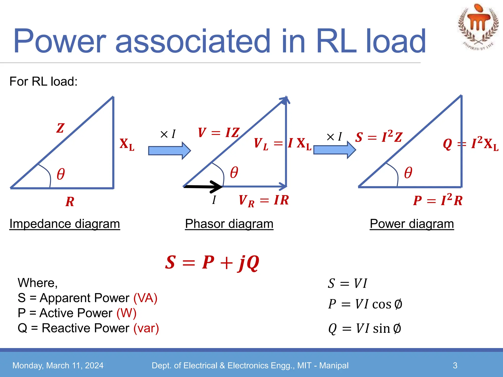
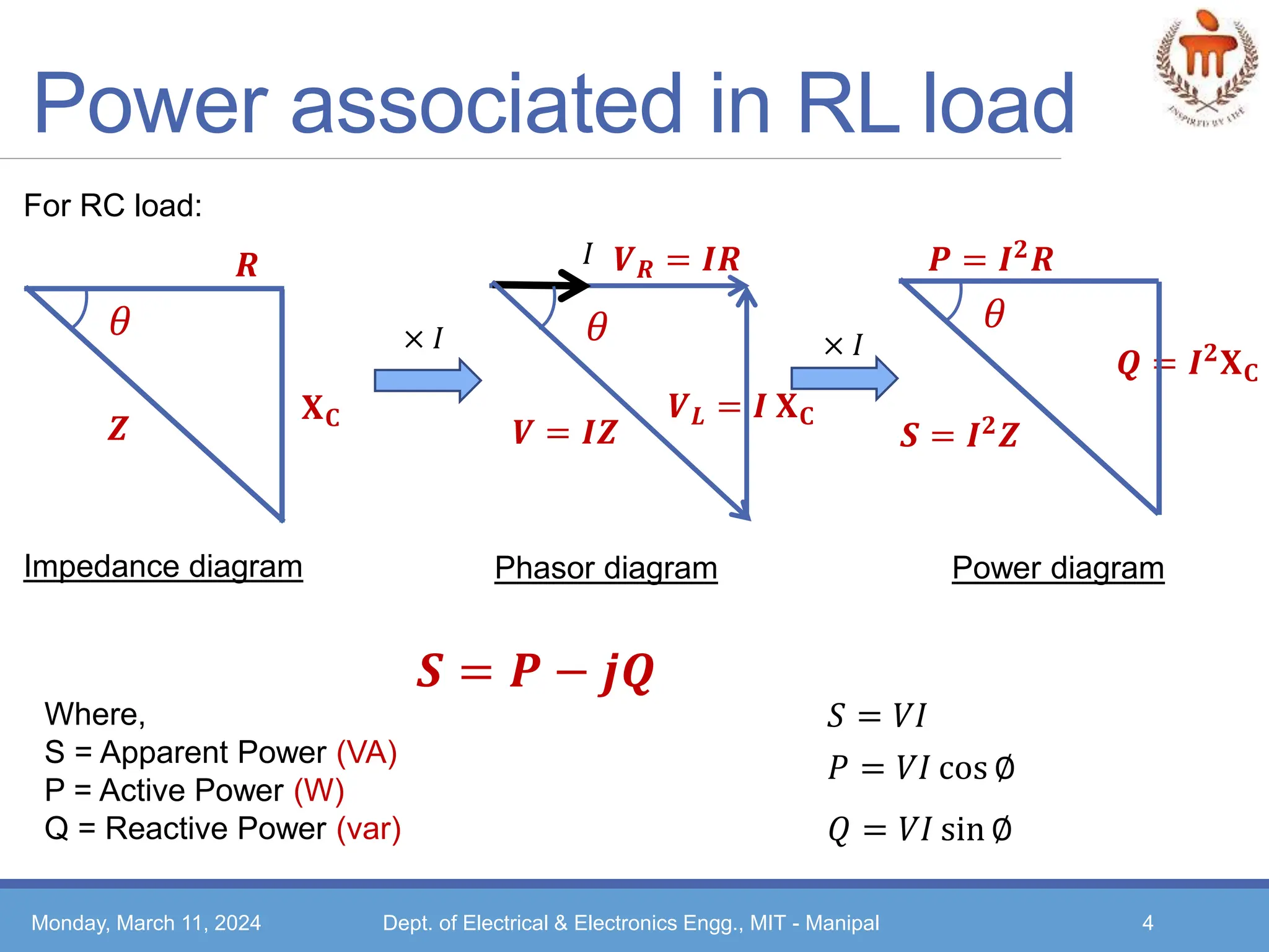
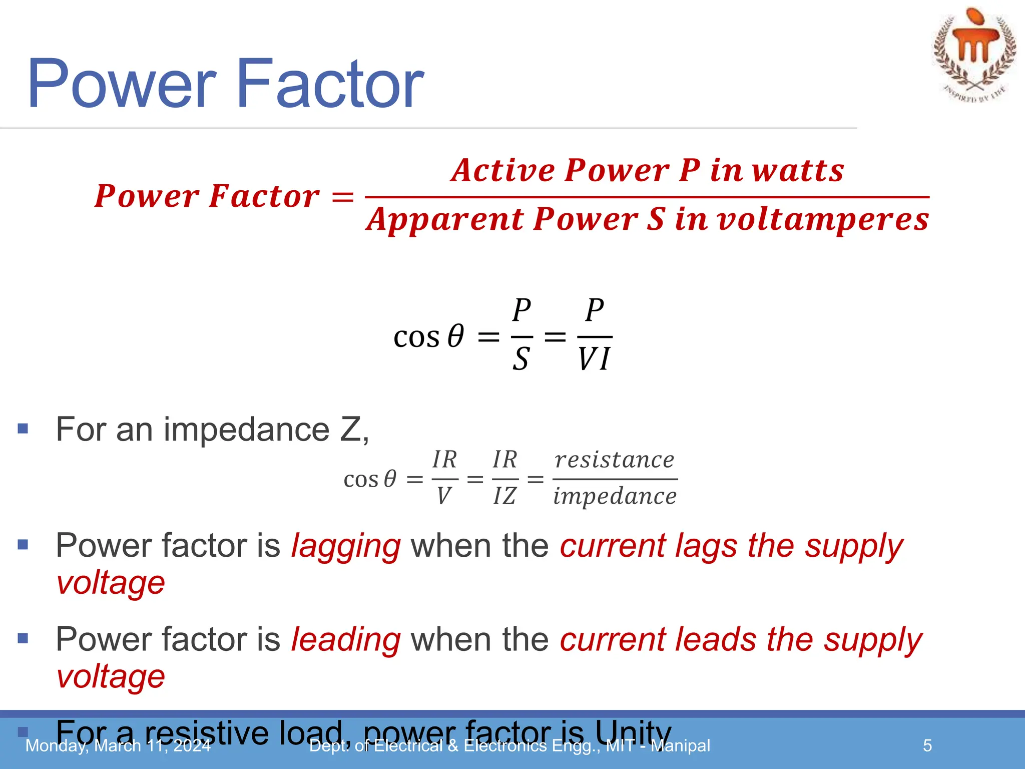
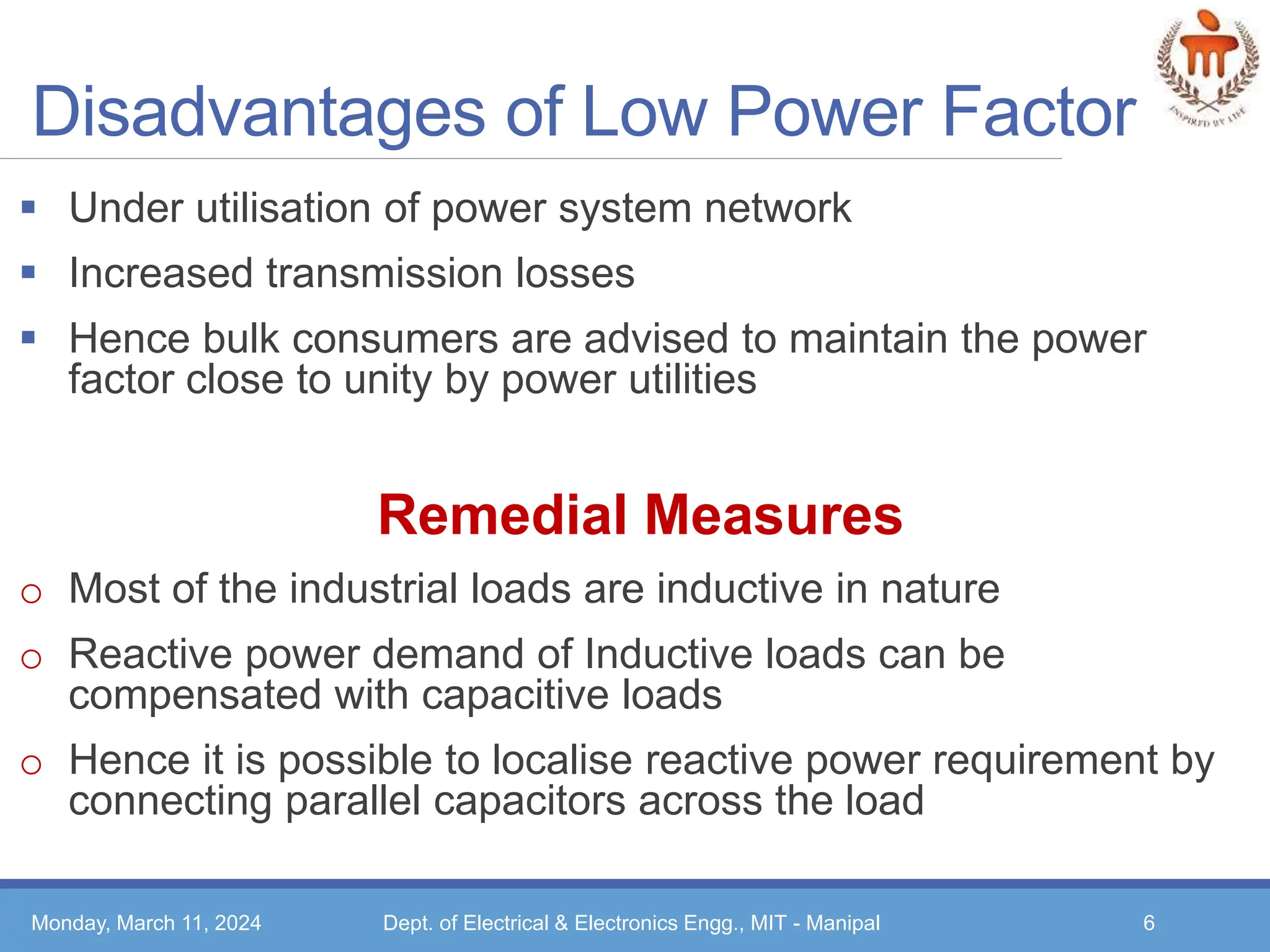
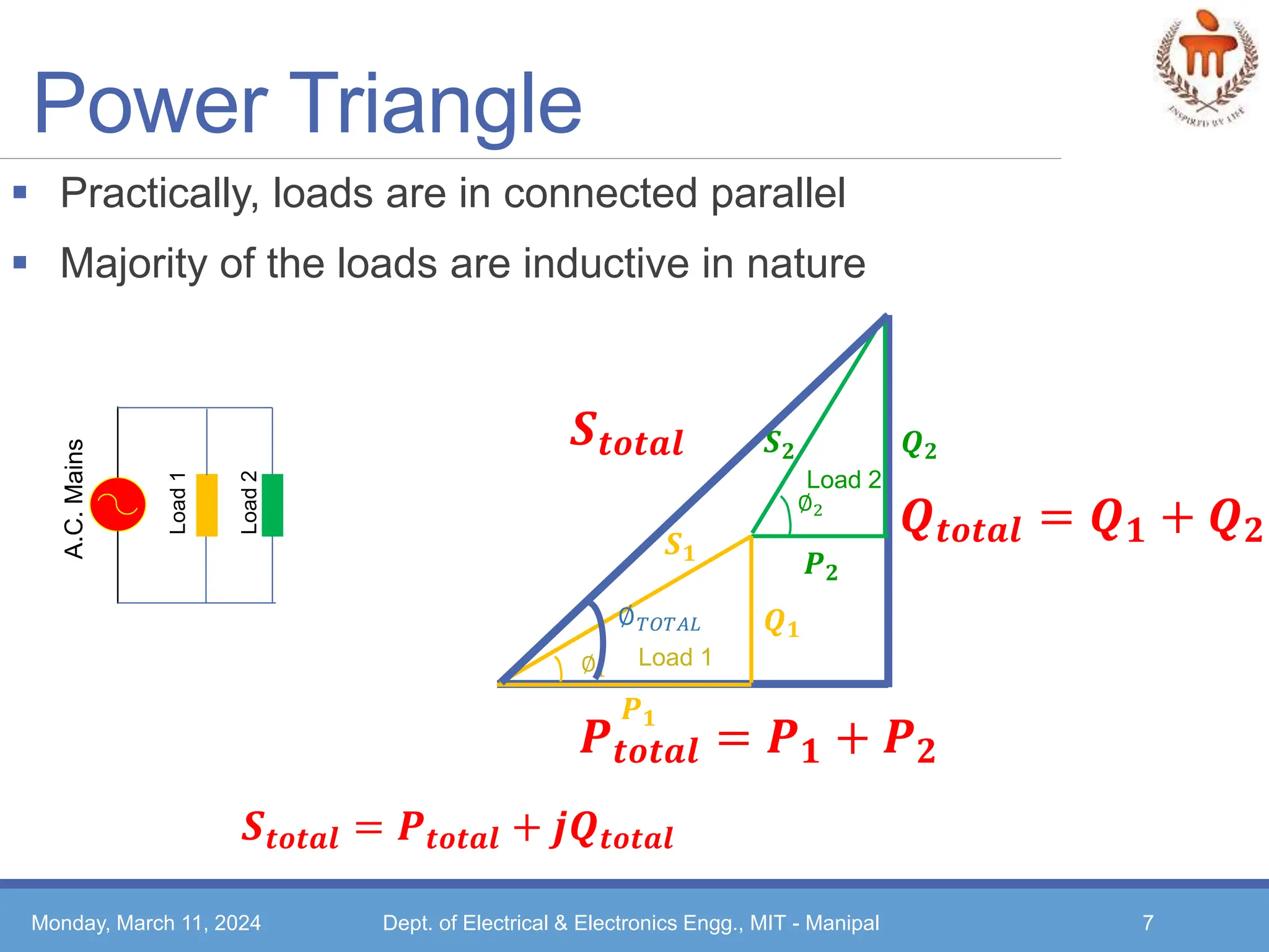
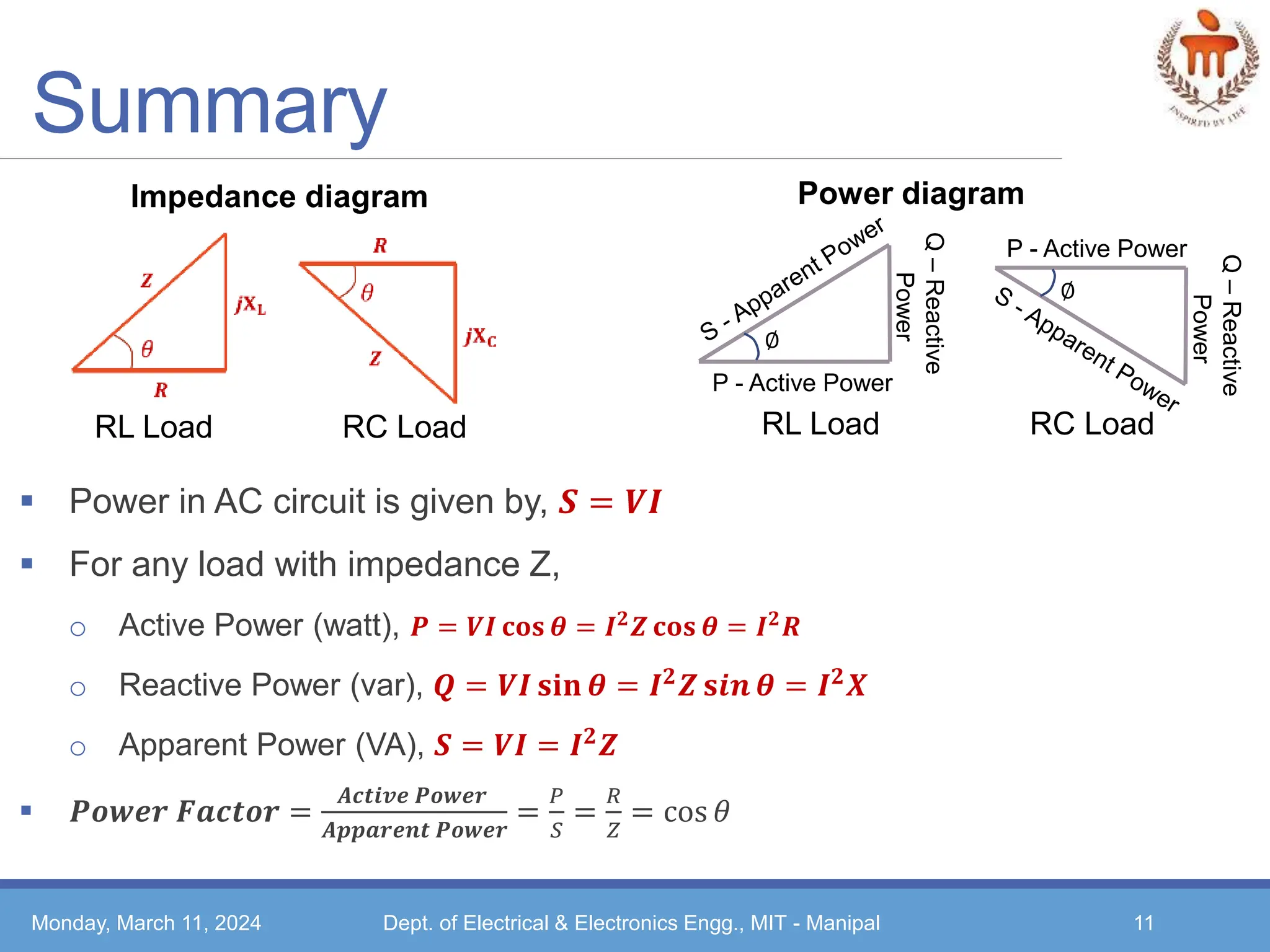
1. Basic Electrical Technology
[ELE 1051]
SINGLE PHASE AC CIRCUITS
L19 – Power in AC circuits
Monday, March 11, 2024 Dept. of Electrical & Electronics Engg., MIT - Manipal 1
2. Topics covered…
Impedance, phasor & Power Diagram
Concept of power factor and its significance
Need for power factor improvement
Monday, March 11, 2024 Dept. of Electrical & Electronics Engg., MIT - Manipal 2
3. Power associated in RL load
Monday, March 11, 2024 Dept. of Electrical & Electronics Engg., MIT - Manipal 3
For RL load:
𝜃
𝑹
𝐗𝐋
𝒁
Impedance diagram
× 𝐼
𝜃
𝑷 = 𝑰𝟐𝑹
𝑸 = 𝑰𝟐𝐗𝐋
𝑺 = 𝑰𝟐𝒁
Power diagram
× 𝐼
𝜃
𝑽𝑹 = 𝑰𝑹
𝑽𝑳 = 𝑰 𝐗𝐋
𝑽 = 𝑰𝒁
𝐼
Phasor diagram
𝑺 = 𝑷 + 𝒋𝑸
𝑆 = 𝑉𝐼
𝑃 = 𝑉𝐼 cos ∅
𝑄 = 𝑉𝐼 sin ∅
Where,
S = Apparent Power (VA)
P = Active Power (W)
Q = Reactive Power (var)
4. Power associated in RL load
Monday, March 11, 2024 Dept. of Electrical & Electronics Engg., MIT - Manipal 4
For RC load:
× 𝐼 × 𝐼
𝑺 = 𝑷 − 𝒋𝑸
Where,
S = Apparent Power (VA)
P = Active Power (W)
Q = Reactive Power (var)
𝜃
𝑹
𝐗𝐂
𝒁
Impedance diagram
𝜃
𝑽𝑹 = 𝑰𝑹
𝑽𝑳 = 𝑰 𝐗𝐂
𝑽 = 𝑰𝒁
𝐼
Phasor diagram
𝑷 = 𝑰𝟐
𝑹
𝑸 = 𝑰𝟐𝐗𝐂
𝑺 = 𝑰𝟐𝒁
Power diagram
𝜃
𝑆 = 𝑉𝐼
𝑃 = 𝑉𝐼 cos ∅
𝑄 = 𝑉𝐼 sin ∅
5. Power Factor
For an impedance Z,
cos 𝜃 =
𝐼𝑅
𝑉
=
𝐼𝑅
𝐼𝑍
=
𝑟𝑒𝑠𝑖𝑠𝑡𝑎𝑛𝑐𝑒
𝑖𝑚𝑝𝑒𝑑𝑎𝑛𝑐𝑒
Power factor is lagging when the current lags the supply
voltage
Power factor is leading when the current leads the supply
voltage
For a resistive load, power factor is Unity
Monday, March 11, 2024 Dept. of Electrical & Electronics Engg., MIT - Manipal 5
𝑷𝒐𝒘𝒆𝒓 𝑭𝒂𝒄𝒕𝒐𝒓 =
𝑨𝒄𝒕𝒊𝒗𝒆 𝑷𝒐𝒘𝒆𝒓 𝑷 𝒊𝒏 𝒘𝒂𝒕𝒕𝒔
𝑨𝒑𝒑𝒂𝒓𝒆𝒏𝒕 𝑷𝒐𝒘𝒆𝒓 𝑺 𝒊𝒏 𝒗𝒐𝒍𝒕𝒂𝒎𝒑𝒆𝒓𝒆𝒔
cos 𝜃 =
𝑃
𝑆
=
𝑃
𝑉𝐼
6. Disadvantages of Low Power Factor
Under utilisation of power system network
Increased transmission losses
Hence bulk consumers are advised to maintain the power
factor close to unity by power utilities
Remedial Measures
o Most of the industrial loads are inductive in nature
o Reactive power demand of Inductive loads can be
compensated with capacitive loads
o Hence it is possible to localise reactive power requirement by
connecting parallel capacitors across the load
Monday, March 11, 2024 Dept. of Electrical & Electronics Engg., MIT - Manipal 6
7. Power Triangle
Practically, loads are in connected parallel
Majority of the loads are inductive in nature
Monday, March 11, 2024 Dept. of Electrical & Electronics Engg., MIT - Manipal 7
A.C.
Mains
Load
2
Load
1
𝑺𝒕𝒐𝒕𝒂𝒍
𝑷𝒕𝒐𝒕𝒂𝒍 = 𝑷𝟏 + 𝑷𝟐
𝑸𝒕𝒐𝒕𝒂𝒍 = 𝑸𝟏 + 𝑸𝟐
𝑺𝒕𝒐𝒕𝒂𝒍 = 𝑷𝒕𝒐𝒕𝒂𝒍 + 𝒋𝑸𝒕𝒐𝒕𝒂𝒍
Load 2
∅2
𝑺𝟐
𝑷𝟐
𝑸𝟐
Load 1
∅1
𝑷𝟏
𝑸𝟏
𝑺𝟏
∅𝑇𝑂𝑇𝐴𝐿
8. Power Factor Improvement
Connect capacitor parallel to the load
Energy stored by the capacitor provides the required reactive power
by the load
Monday, March 11, 2024 Dept. of Electrical & Electronics Engg., MIT - Manipal 8
𝑺𝒕
𝑷𝒕
𝑸𝒕
∅𝑇𝑂𝑇𝐴𝐿
Load
2
Load
1
A.C.
Mains
capacitor
𝑺𝒕
𝑷𝒕
𝑸𝒄
∅𝑇𝑂𝑇𝐴𝐿
∅𝑛𝑒𝑤
𝑸𝒏𝒆𝒘 = 𝑸𝒕 − 𝑸𝒄
𝑺𝒏𝒆𝒘
• Calculate 𝑄𝑐needed to improve power factor to 𝑐𝑜𝑠∅𝑛𝑒𝑤
• Calculate 𝑋𝑐 =
𝑉2
𝑄𝐶
& c =
𝑋𝑐
2𝜋𝑓
Calculation of capacitor value
9. Illustration 1
A single-phase motor takes 8.3 A at a power factor of 0.866
lagging when connected to a 230 V, 50 Hz supply. Capacitance
bank is now connected in parallel with the motor to raise the
power factor to unity. Determine the capacitance value
Monday, March 11, 2024 Dept. of Electrical & Electronics Engg., MIT - Manipal 9
Ans: 𝟓𝟕. 𝟒 𝝁𝑭
10. Illustration 2
A single-phase load of 5 kW operates at a power factor of 0.6
lagging. It is proposed to improve this power factor to 0.95
lagging by connecting a capacitor across the load. Calculate the
kvar rating of the capacitor
Monday, March 11, 2024 Dept. of Electrical & Electronics Engg., MIT - Manipal 10
Ans: 5.02 kvar
11. Summary
Power in AC circuit is given by, 𝑺 = 𝑽𝑰
For any load with impedance Z,
o Active Power (watt), 𝑷 = 𝑽𝑰 𝐜𝐨𝐬 𝜽 = 𝑰𝟐
𝒁 𝐜𝐨𝐬 𝜽 = 𝑰𝟐
𝑹
o Reactive Power (var), 𝑸 = 𝑽𝑰 𝐬𝐢𝐧 𝜽 = 𝑰𝟐
𝒁 𝐬𝒊𝒏 𝜽 = 𝑰𝟐
𝑿
o Apparent Power (VA), 𝑺 = 𝑽𝑰 = 𝑰𝟐
𝒁
𝑷𝒐𝒘𝒆𝒓 𝑭𝒂𝒄𝒕𝒐𝒓 =
𝑨𝒄𝒕𝒊𝒗𝒆 𝑷𝒐𝒘𝒆𝒓
𝑨𝒑𝒑𝒂𝒓𝒆𝒏𝒕 𝑷𝒐𝒘𝒆𝒓
=
𝑃
𝑆
=
𝑅
𝑍
= cos 𝜃
Monday, March 11, 2024 Dept. of Electrical & Electronics Engg., MIT - Manipal 11
Impedance diagram
RL Load RC Load
Power diagram
RL Load RC Load
∅
P - Active Power
Q
–
Reactive
Power
∅
P - Active Power
Q
–
Reactive
Power
12. Summary
Low power factor loads must be avoided
Capacitor bank connected parallel to the load serves as the
source of reactive power for the load
o Improves load power factor
o Reduces transmission and distribution losses
Monday, March 11, 2024 Dept. of Electrical & Electronics Engg., MIT - Manipal 12