Download as PDF, PPTX


![Observations: CBD definition(1)
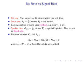
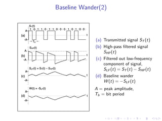
Define Cumulative bit difference(CBD), difference between the number of
transmitted zeros and the number of transmitted ones2
,
CBD[n] = N0[n] − N1[n] (7)
where CBD[n] = cumulative bit difference at the n-th bit of the pattern
N0 = cumulative number of 0s in the pattern up to the n-th bit
N1 = cumulative number of 1s in the pattern up to the n-th bit
2 NRZ Bandwidth – LF Cutoff and Baseline Wander, Maxim Integerted](https://image.slidesharecdn.com/dcnldtalks4-200501063406/85/Baseline-Wandering-14-320.jpg)
![Observations
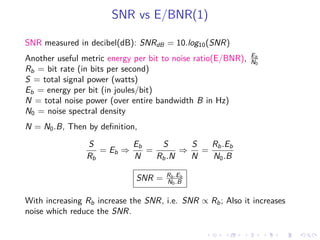
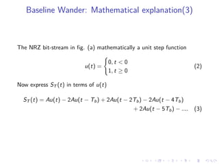
Magnitude of baseline wander in NRZ determined by CBD[n] and LF
cutoff.
Baseline wander changes fastest when there are consecutive identical
digits(CID), and this also changes the CBD too.
Apart from CIDs, and imbalance in number of 0s and 1s create
wandering.
The baseline wander depend on the CBD only when the CBD is
computed over a number of bit periods that constitute a small
fraction of one time constant.](https://image.slidesharecdn.com/dcnldtalks4-200501063406/85/Baseline-Wandering-15-320.jpg)
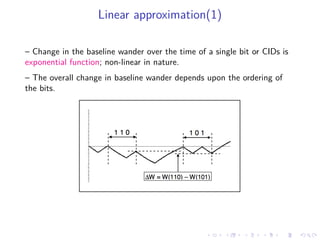
![Linear approximation(2)
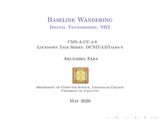
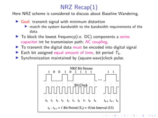
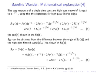
– Assumption: rate of change of baseline wander is constant(i.e. linear).
– For linear baseline wander, the offset will adds up linearly irrespective of
the bit pattern.
– Then approximate baseline wander can be a function of local CBD.
using the linear approximation, eqn.(6) reduced to,
W (t) = −Au(t) 1 −
t
Tb
+ 2Au(t − Tb) 1 −
t − Tb
τ
(8)
– Taking summation over entire bit sequence in eqn.(8)
W (t) = CBD[n] ×
Tb
τ
(9)](https://image.slidesharecdn.com/dcnldtalks4-200501063406/85/Baseline-Wandering-17-320.jpg)
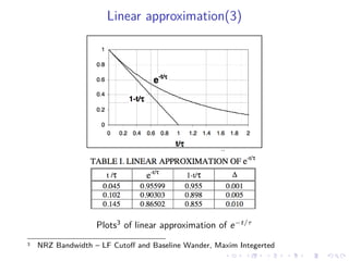


The document discusses baseline wandering in digital transmission, particularly in non-return-to-zero (NRZ) encoding, and its impact on bit error rates. It explores the mathematical explanations, observations, and effects of baseline wander, emphasizing how cumulative bit difference (CBD) and low-frequency (LF) cutoff influence the phenomenon. The document concludes that managing baseline wander involves ensuring an equal number of transmitted zeros and ones, alongside coding techniques to mitigate its effects.