Download to read offline
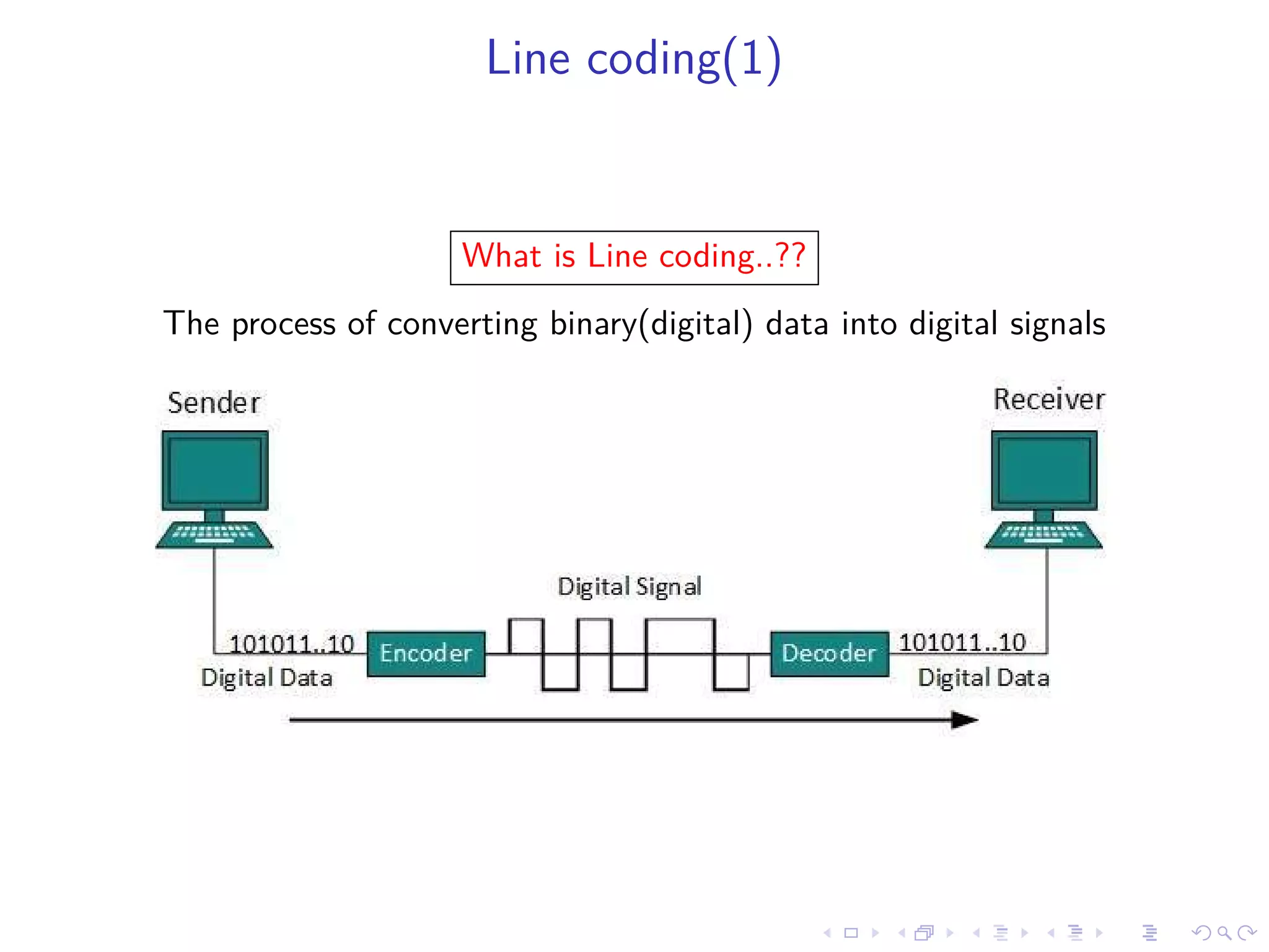
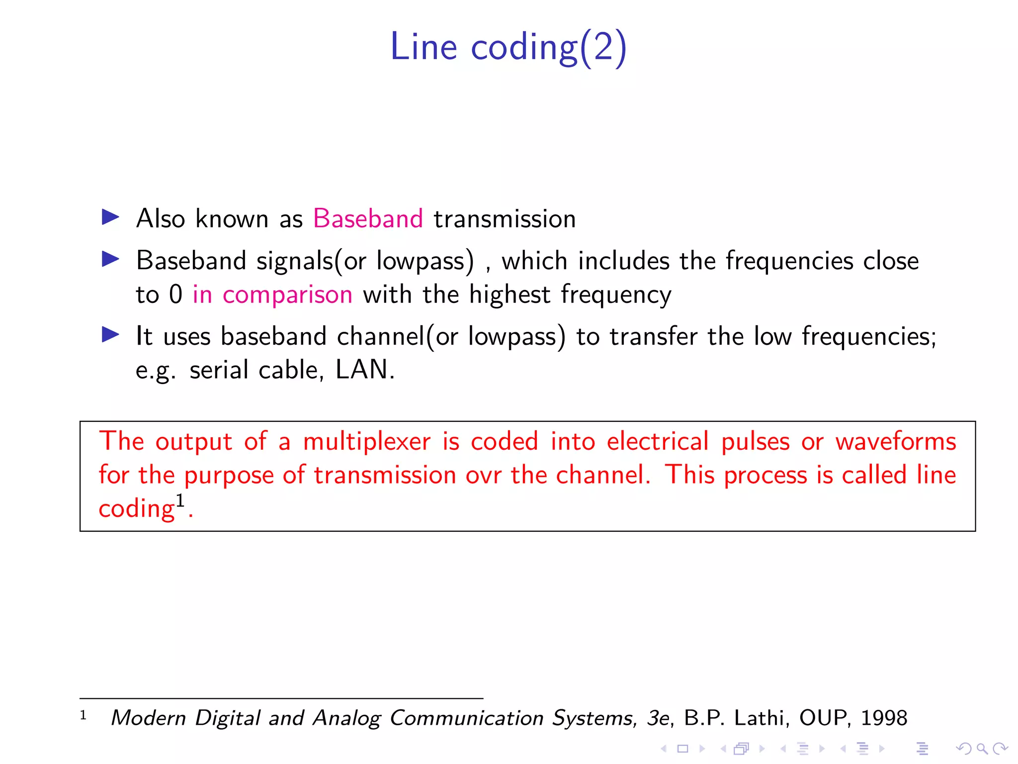
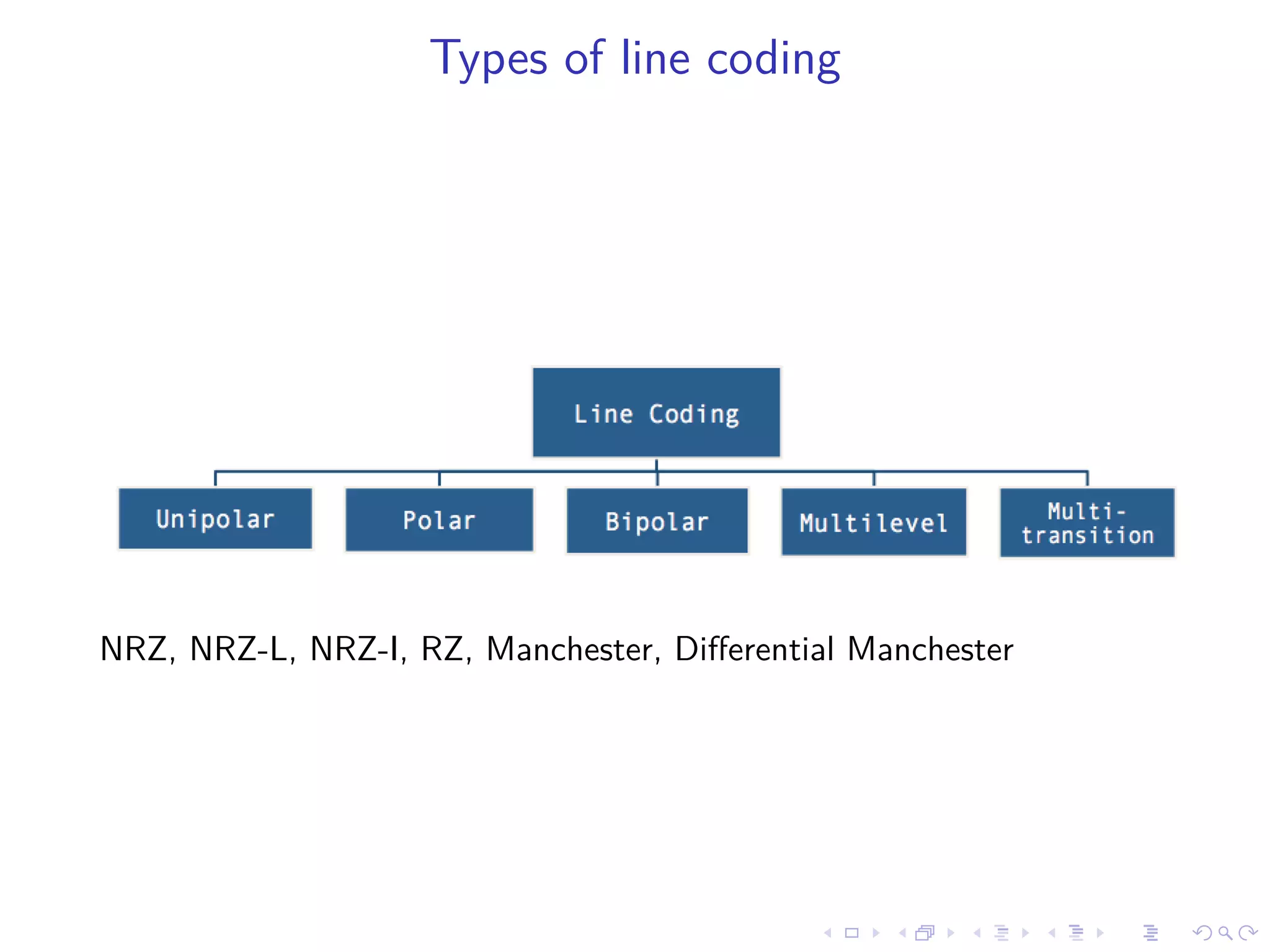
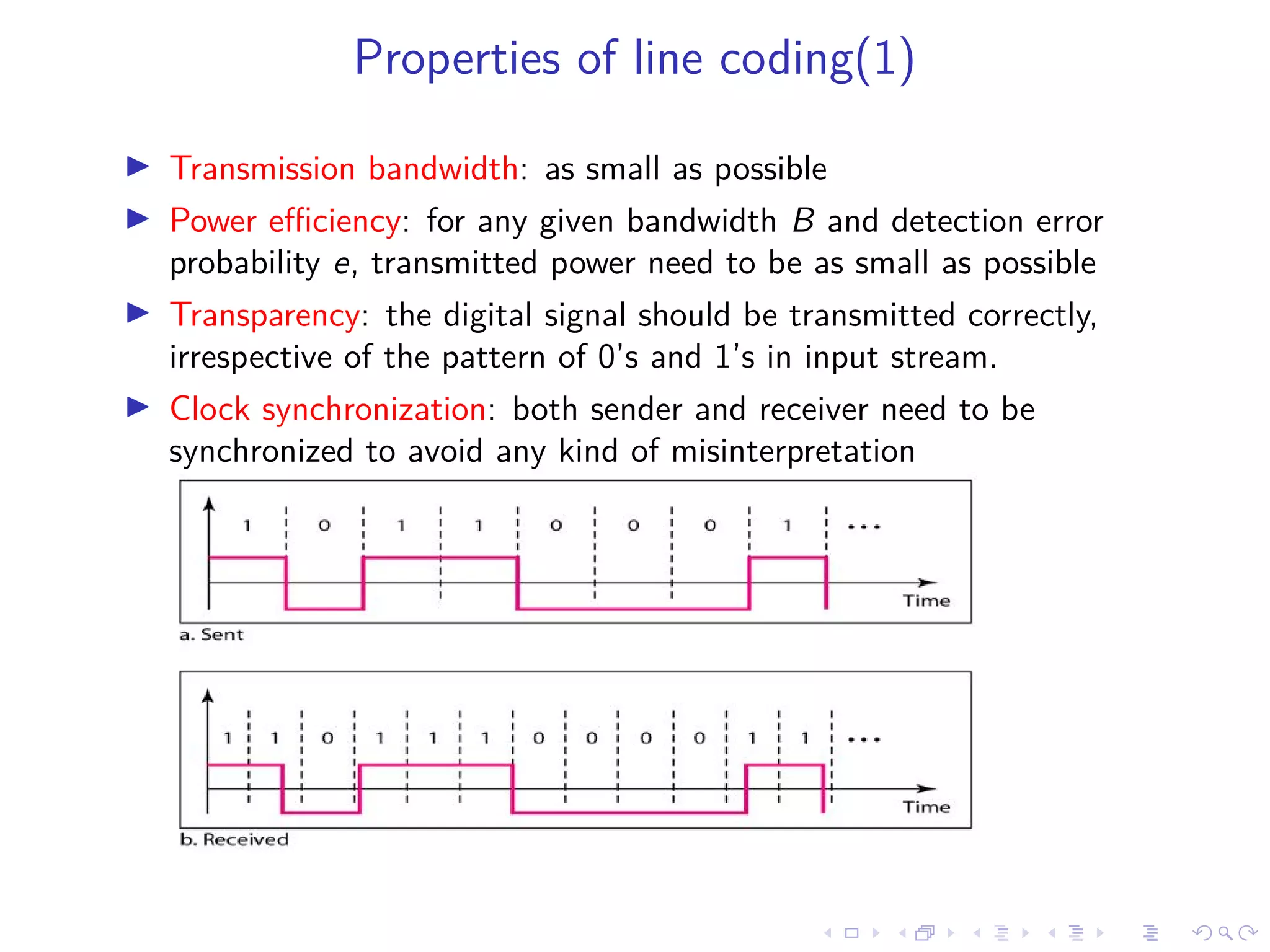

Line coding schemes are used to convert digital data into electrical signals for transmission over channels. This document outlines various line coding techniques such as NRZ, Manchester, and Differential Manchester coding. It discusses properties of good line coding schemes, including low transmission bandwidth, power efficiency, transparency, clock synchronization, error handling, and prevention of baseline wandering. Line coding is important for digital transmission in applications such as local and wide area networks, pulse shaping, and telephonic transmission.