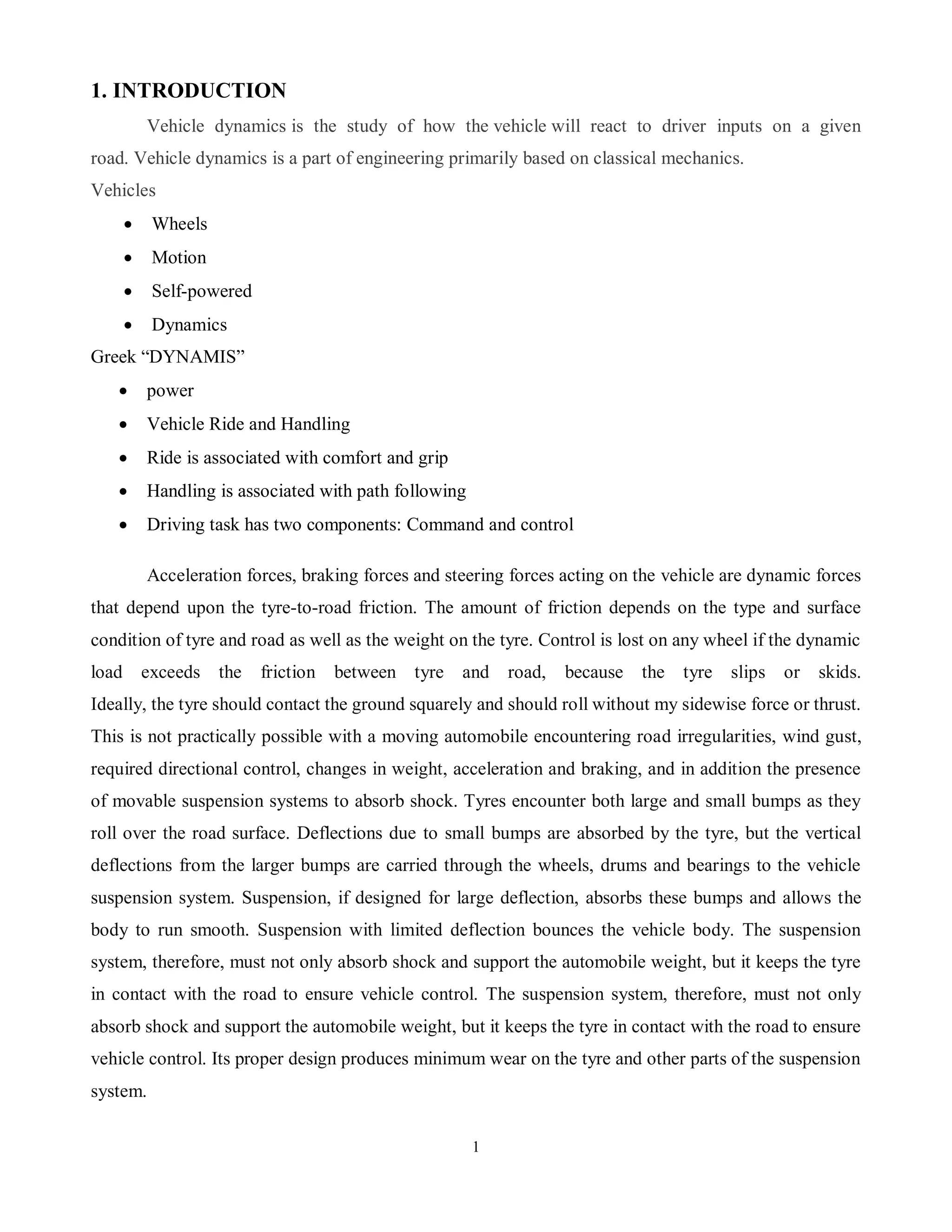
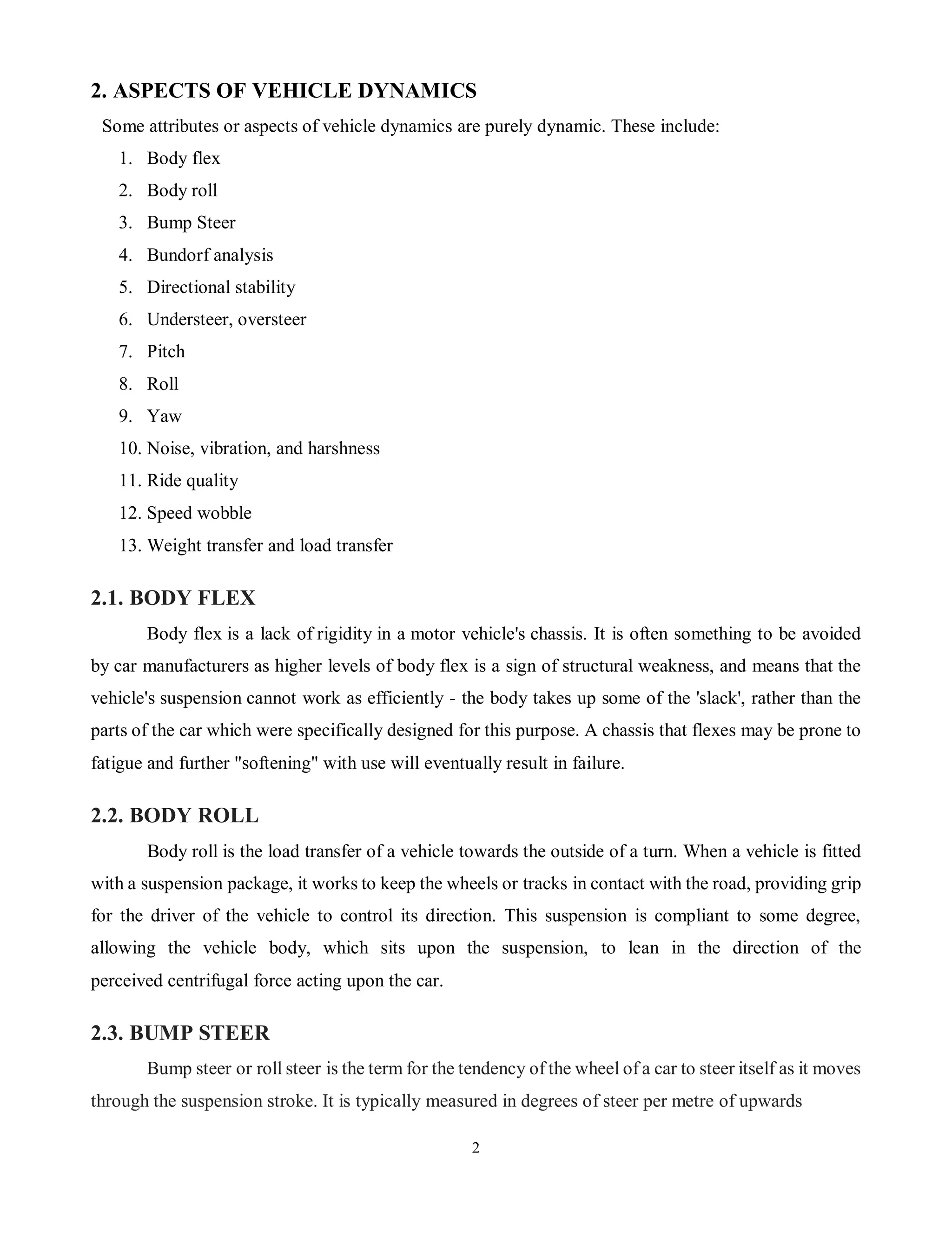
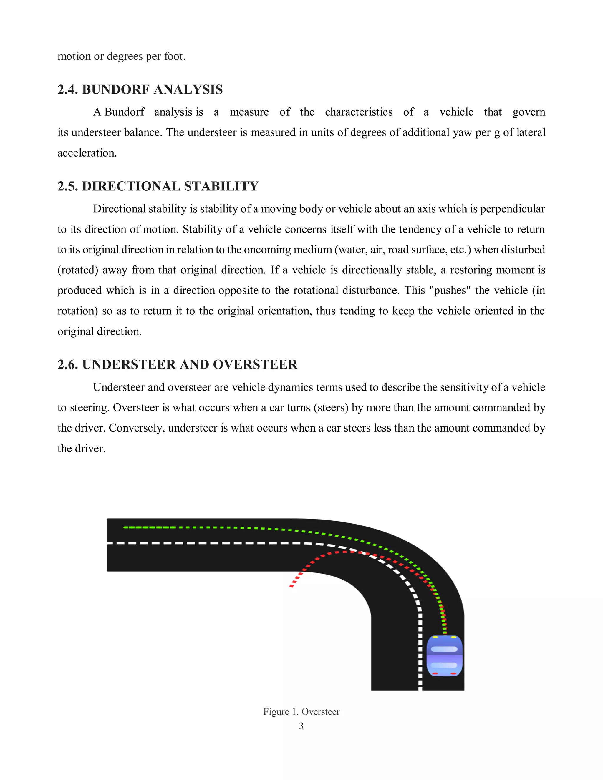
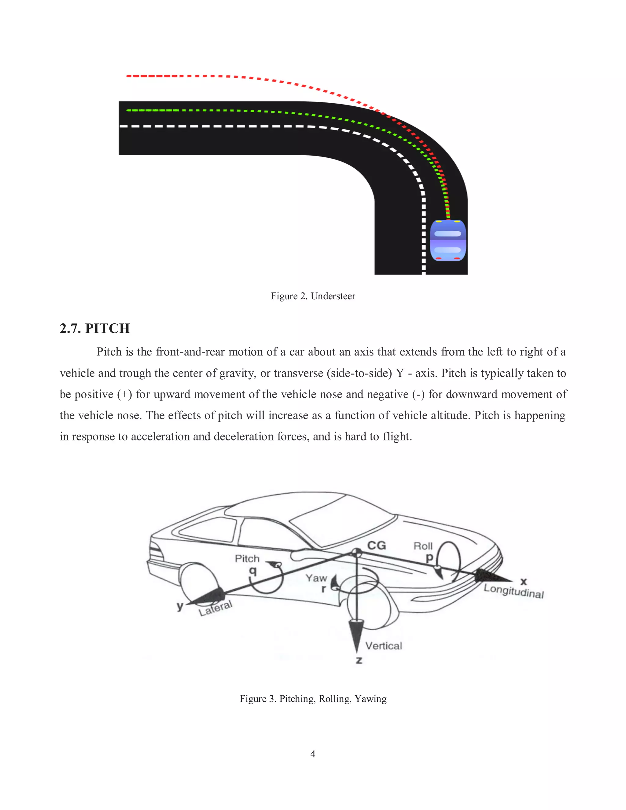
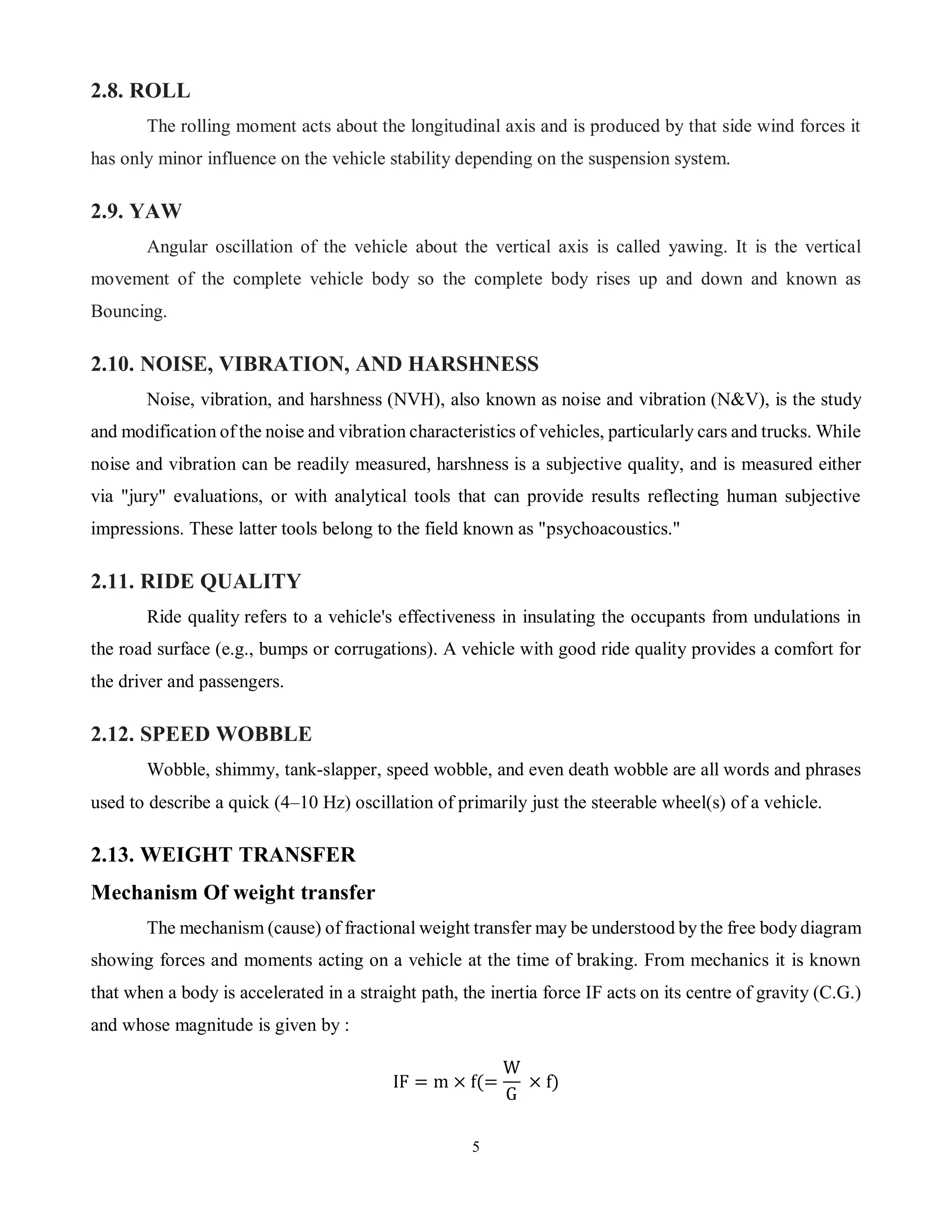
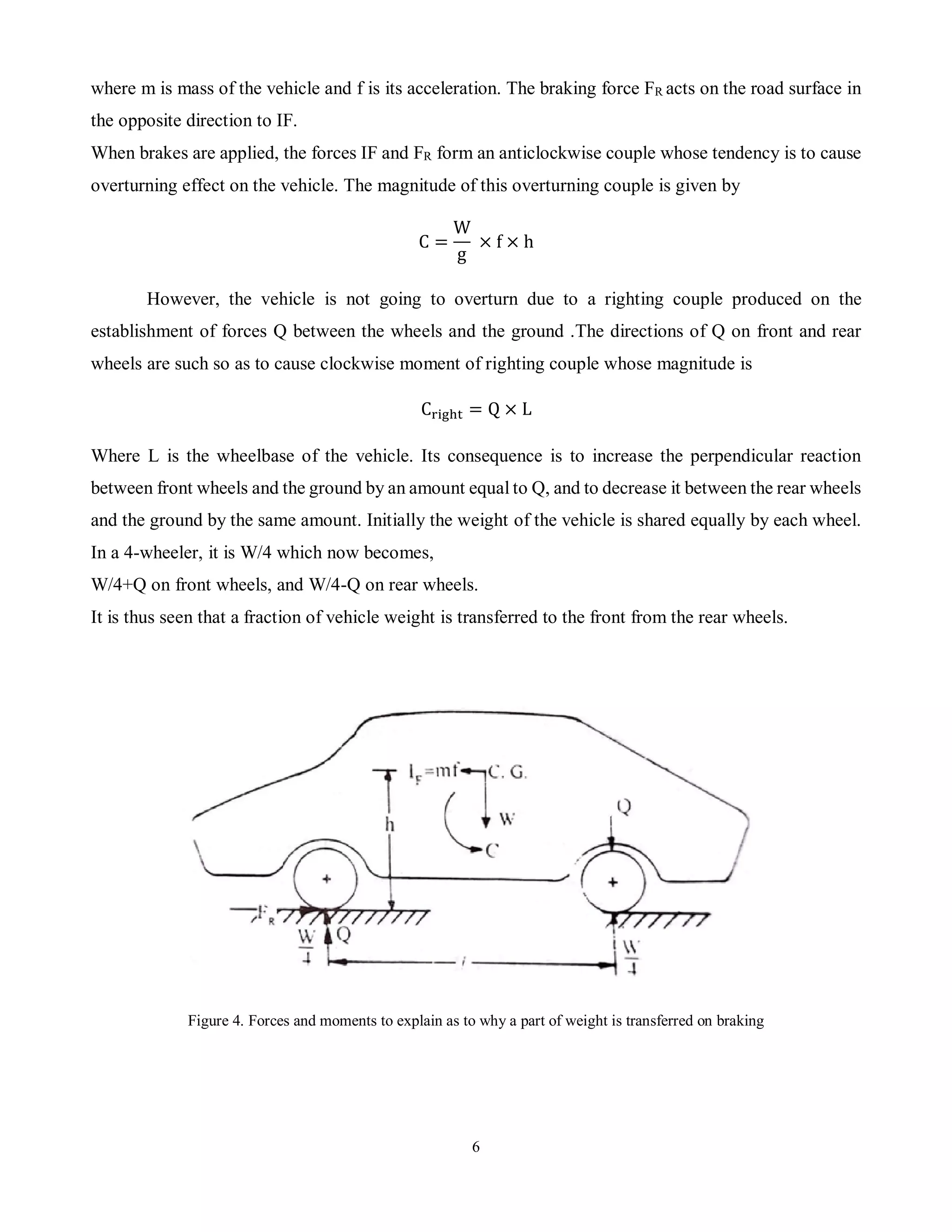
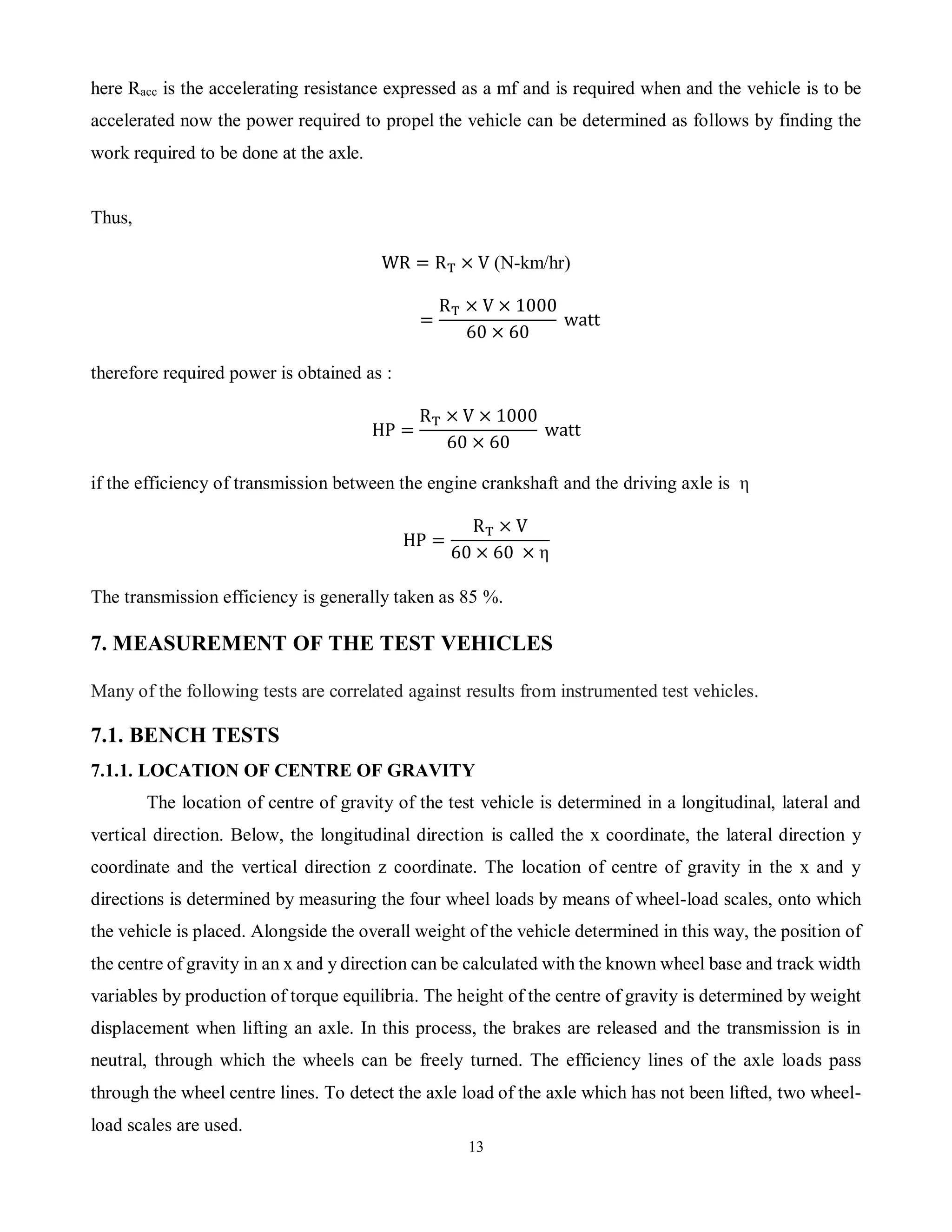
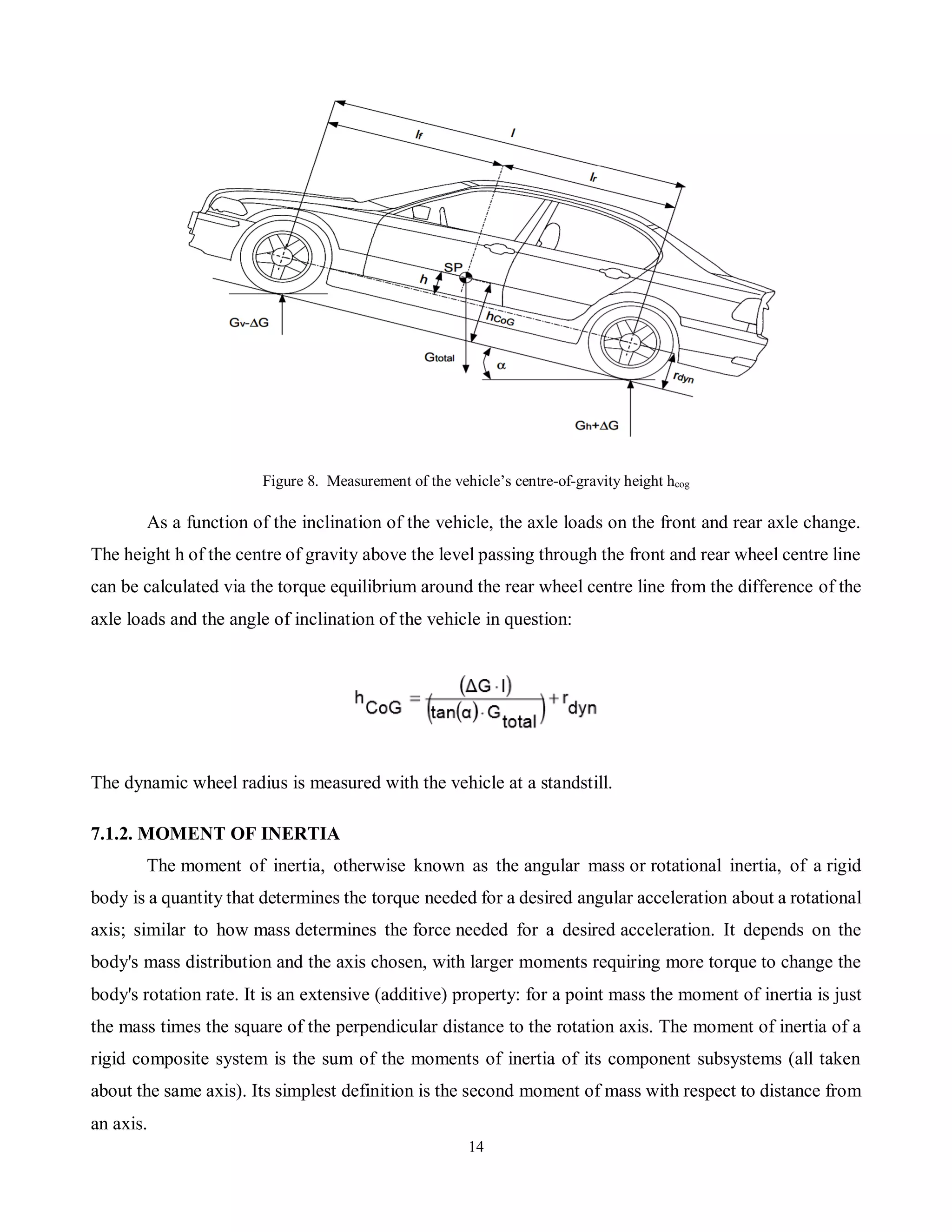
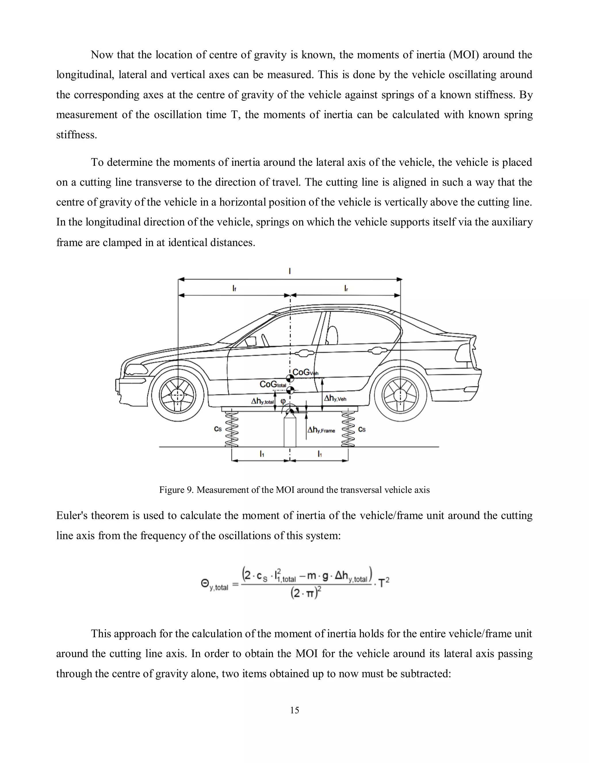
This document provides an introduction to vehicle dynamics and its key concepts. It discusses topics such as ride and handling, suspension systems, forces acting on vehicles, vehicle motion including pitch, roll and yaw, and power characteristics. Vehicle dynamics is the study of how vehicles react to driver inputs based on mechanics. Key aspects covered include body flex, weight transfer during braking, types of steering like understeer and oversteer, suspension design impacts on ride quality, and engine power outputs. The document provides a high-level overview of fundamental vehicle dynamics principles.
This document discusses vehicle dynamics and tools used to assess vehicle dynamics. It begins with an introduction defining vehicle dynamics as the study of how a vehicle reacts to driver inputs based on classical mechanics. It then outlines several key aspects of vehicle dynamics including body flex, roll, bump steer, stability, and understeer/oversteer. The document also discusses engine power output metrics like indicated power and brake power. It concludes by examining automotive resistances like rolling resistance, frictional resistance, gradient resistance, and air resistance that reduce the propulsive power of a vehicle.
The document provides an overview of power steering systems. It discusses the history of power steering from its invention in the early 1900s to its use in automobiles and agricultural vehicles. The key components of power steering systems are described including the reservoir, steering gearbox, rotary valve, and pump. The main types of power steering systems - hydraulic, electro-hydraulic, and electric - are outlined along with diagrams of how each system works. Advantages like reduced driver fatigue and continuous steering are balanced with potential disadvantages such as leakage and vibration.
This 3 sentence summary provides an overview of the key details from the document:
The document is a final design report for an all-terrain vehicle (ATV) created by a group of mechanical engineering students to fulfill their degree requirements. It includes sections on frame design and analysis, suspension system, steering, braking, engine and transmission selection, and safety features. The goal was to design a single-seat, high-performance off-road vehicle that can handle rugged terrain with maximum safety and comfort.
This document provides an overview of a vehicle dynamics course. It discusses topics that will be covered such as vehicle dynamics fundamentals, load transfer, acceleration and braking performance, wheel alignment, handling, ride forces, suspension technologies, tires, and vehicle dynamic tests. The course will examine chapters on vehicle dynamics, longitudinal and lateral load transfer, tractive effort and forces, weight transfer, and the relationship between road loads and tractive resistance. It also provides examples of vehicle dynamic field tests. The goal is for students to gain an understanding of key vehicle dynamics concepts and metrics.
Active suspension System of Automobiles.Mayank khare
An active suspension system,has the capability to adjust itself continuously to changing road conditions. It "artificially" extends the design parameters of the system by constantly monitoring and adjusting itself, thereby changing its character on an ongoing basis. It's schizophrenic, if you will, but with a purpose. With advanced sensors and microprocessors feeding it information all the time, its identity remains fluid, contextual, amorphous. By changing its character to respond to varying road conditions, active suspension offers superior handling, road feel, responsiveness and safety.
Study of transmission system of automobileNikhil Chavda
The document summarizes the transmission system of an automobile. It defines the transmission system as the mechanism that transmits power from the engine to the driving wheels. It has three main components - the clutch, gearbox, and propeller shaft. The transmission allows the engine to be disconnected from the wheels, connected smoothly, and drives the wheels at different speeds. It enables torque multiplication for starting and leverage variation between the engine and wheels. The document discusses different types of transmission systems including mechanical, hydraulic, electrical and automatic systems. It also explains the power flow in sliding mesh and constant mesh gearboxes.
The document describes the different layouts of automobiles, including where the engine and drive wheels are located. It discusses the main types - front engine rear wheel drive, rear engine rear wheel drive, and front engine front wheel drive. For each type, it provides details on their characteristics such as noise isolation, drive train loss, weight distribution, and handling. The document aims to explain the different configurations and their respective advantages and limitations.
Google announced its first fully functional driverless car ready for testing on public roads, marking a breakthrough in automotive technology. Automakers are also developing automated manual transmissions, vehicle-to-vehicle communication technologies, and advanced driver assistance systems using sensors and automatic braking to increase safety and prevent collisions. Meanwhile, new infotainment systems are allowing smartphone-like interfaces in vehicles, and materials like aluminum are making cars lighter and more fuel efficient.
basic aerodynamic design consideration of automobile, importance of car aerodyanamic design, various aerodynamic devices use in car body,different tools require for anlysis of aerodynamic
automobile workshop ppt Traning report by c rang rajan and sudhir kumarchakrawarti rang rajan
The document provides an overview of the key components and systems of an automobile. It begins with an introduction to Karlo Automobiles, an Indian vehicle repair workshop. It then defines an automobile and describes its main parts like the engine, transmission system including the clutch, gearbox, propeller shaft, differential, wheels, axle and chassis. The document further explains the body, suspension system, cooling system, steering system, braking system and lighting system of a car. Diagrams and pictures are included to illustrate the different components. The presentation aims to provide trainees an understanding of the various parts that make up a motor vehicle.
Frame and Body of Automobile
Introduction to chassis, Classification of chassis, Conventional chassis,
Semi forward chassis, Full forward chassis, Engine at the front, Engine at the rear, Engine in mid, Frame of the automobile, Function of Frame, types of frame, conventional frame, semi-integral frame, integral frame, defects in chassis, Body of the automobile, types of the body in automobile,
This document discusses replacing traditional leaf springs in vehicles with composite leaf springs made of fiberglass-reinforced plastic. It begins by introducing composite materials and their benefits of lighter weight, stiffness, and corrosion resistance. Leaf springs are then described as flat plates commonly used in heavy vehicles for suspension. Analysis was performed in ANSYS to compare the stress, strain, bending stress, and deformation of traditional steel leaf springs and composite leaf springs under different loads. The results show the composite leaf springs can reduce weight by around 60% while increasing fatigue life and providing benefits like better damping and corrosion resistance over steel springs.
The document describes the fabrication of a four wheel steering system for a Maruti 800 vehicle. Key points:
- The rear wheels were modified to allow for steering capability by adding a second rack and pinion steering gearbox connected to the original front gearbox via transfer rods and bevel gears.
- In rear steer mode at low speeds, the rear wheels turn in the opposite direction of the front wheels, greatly reducing the turning radius.
- Benefits of the four wheel steering system include improved vehicle handling, stability, and reduced driver fatigue over long drives due to the easier steering capability.
- The successful implementation of the system allows for increased maneuverability and stability of vehicles.
The document discusses vehicle steering systems. It begins with an introduction to basic steering components and principles. It then covers various topics related to steering mechanisms, including Davis and Ackerman steering mechanisms. It also discusses steering ratio, steering lock, steering gear boxes including different types, and power steering. The document provides information on key factors for proper steering such as steerability and stability.
The document is a PowerPoint presentation on automobile engineering given by Assistant Professor Mahesh Kumar. It covers topics such as the basic concepts of automobile engineering, classifications of automobiles, transmission systems including clutches, gear ratios, driveshafts and differentials, and other systems like steering, brakes and suspension. The presentation provides an overview of key terms and components in automobile engineering.
Steering gears - worm and wheel steering gearBASURI NIKHIL
The document discusses different types of steering gears used in vehicles. It focuses on the worm and wheel steering gear. It describes how the worm and wheel steering gear system works, with a worm keyed to the steering shaft that meshes with a worm wheel mounted in bearings in a cast iron case. The worm wheel is connected to steering linkages to convert the rotary motion of the steering wheel into linear motion of the front wheels. Worm gears can increase torque or reduce speed while providing a smooth and quiet operation. However, they also have high power losses and generate heat.
This document discusses active suspension systems. It begins by outlining the requirements of a conventional suspension system, then classifies suspension systems as either active, passive, or semi-active. It describes how active suspension systems use actuators like hydraulics, pneumatics, or electromagnetics to control wheel position independently. Active suspension provides advantages like improved handling and ride quality but has higher costs and weight compared to conventional systems. The document concludes by discussing military applications of active suspension and the future potential of the technology.
This document discusses aerodynamics in cars. It begins by defining aerodynamics and classifying different types. It then discusses how aerodynamics affects forces on a car like lift, drag, downforce, and thrust. The document traces the evolution of aerodynamic design in cars from the early 20th century to the 1970s when fuel efficiency became important. It describes methods to evaluate aerodynamics like wind tunnels and simulation software. The document highlights various aerodynamic devices used in cars like wings, spoilers, ducts and diffusers and how they impact speed, downforce, and fuel efficiency.
This document provides an overview of steering systems for vehicles. It discusses the basic requirements and functions of a steering system, which include controlling the direction of vehicle wheels, providing stability while driving straight, and minimizing tire wear. It then describes the principles of Ackermann steering geometry and the conditions for proper steering. Finally, it outlines different types of steering mechanisms, focusing on rack and pinion steering gears, which convert the rotational motion of the steering wheel to linear motion at the wheels.
Electric cars are automobiles, which are powered by the electric engine and electric energy. The development of the electric vehicles is a very perspective and important process. Scientists and engineers managed to create electric engines which are no less effective than the ordinary engines used today. It is obvious that electric cars are more ecologically safe and require less energy for work. EVs provide fast acceleration by delivering power instantly to the wheels by providing high torque at low speeds; they give a feel of smooth and quick responsiveness (Technology).
Electromagnetic suspension system in two wheelersswapnil bhosale
The document summarizes a seminar on electromagnetic suspension systems for two-wheelers. It discusses how electromagnetic suspension works by using electromagnets and a feedback loop to control magnetic fields and levitate objects. This eliminates friction and reduces energy consumption compared to traditional spring-based suspensions. The document reviews various research papers on electromagnetic suspension systems that conclude they can improve comfort and stability over passive suspensions. Electromagnetic suspension is presented as a promising technology for vehicles due to advantages like durability, low maintenance, and ability to adapt stiffness as needed.
Active suspension system
An active suspension is a type of automotive suspension on a vehicle. It uses an onboard system to control the vertical movement of the vehicle's wheels relative to the chassis or vehicle body rather than the passive suspension provided by large springs where the movement is determined entirely by the road surface. So-called active suspensions are divided into two classes: real active suspensions, and adaptive or semi-active suspensions. While adaptive suspensions only very shock absorber firmness to match changing road or dynamic conditions, active suspensions use some type of actuator to raise and lower the chassis independently at each wheel.
The document provides an overview of automobiles and automobile power plants. It discusses the classification of automobiles based on use, capacity, make, fuel used, body style, wheels, drive, and transmission. The major components of an automobile including the frame, suspension, power plant, transmission system, electrical system, and control systems are described. Different automobile layouts such as front-engine rear-wheel drive, rear-engine rear-wheel drive, and front-engine front-wheel drive are summarized. Safety features in cars like seat belts, air bags, anti-lock brakes, and electronic stability control are highlighted. Different types of automobile power plants including internal combustion engines, electrical vehicles, fuel cells, and hybrid systems are
Transmission system of ICE Vehicles and Electric VehiclesAvishek Das Gupta
This presentation is about the operating principle of the transmission system in ICE vehicles and electric vehicles. Here I discussed the comparison of ICE vehicles and electric vehicles from the point of view of torque. In this presentation, the basic principle of manual transmission system is described. In automatic transmission system, the objective and working principle of the planetary gear set and the torque converter are described. The schematic diagram of the single-speed transmission system is shown. Difference between the single-speed transmission system and the two-speed transmission system is also shown from the point of view of torque.
The document discusses two-wheelers in India, including their chassis and components. It notes that India is the second largest producer of two-wheelers globally. The main types are motorcycles and mopeds. The chassis is the main frame that supports all other vehicle components like the engine, gearbox, brakes, and suspension system. Some leading manufacturers of motorcycles include Bajaj Auto, Royal Enfield, Yamaha and TVS, while Honda and Hero are top moped producers. Two-wheelers are very popular in India due to their affordable price, fuel efficiency and safety.
This document provides information on various types of transfer cases and differentials used in 4WD and AWD vehicles. It discusses how transfer cases are used to distribute torque to the front and rear axles. Integral transfer gears and part-time 4WD systems are described. Limited slip and locking differentials are also summarized, which help provide traction when one wheel loses grip.
Vehicle dynamics is the study of how a vehicle reacts to driver inputs based on classical mechanics. It examines attributes like body roll, bump steer, weight transfer, and ride quality. There are different types of engine power like indicated power (at the cylinder) and brake power (at the crankshaft). Automotive resistances that reduce usable power include rolling resistance, road gradient resistance, and air resistance. Tests are conducted to find properties like the center of gravity location, moments of inertia, and brake force distribution which enhance vehicle stability, steering control, and overall design.
This document discusses suspension systems for vehicles. It begins by defining suspension systems and their dual purposes of contributing to vehicle handling/safety while providing passenger comfort. It then describes some of the key design conflicts around suspension geometry. Specifically, it discusses how cornering forces can cause the contact patch to deform in undesirable ways. It provides examples of different suspension geometries and how they affect camber angle and contact patch deformation during turns and over bumps. The document outlines the objectives of reducing passenger discomfort, improving safety, and reducing slip during corners. It concludes by describing various properties of suspension systems that are important to consider in the design process such as spring rate, wheel rate, weight transfer, travel, damping, and more.
This document provides an introduction to hybrid vehicles and their components. It discusses how hybrid vehicles combine two power sources, such as gasoline/electric. It also summarizes the characteristics of conventional vehicles, vehicle performance factors like speed and acceleration, vehicle resistance forces, and the characteristics of vehicle power sources and transmissions.
Yaw stability of single versus tandem axle tractorsRoberto Davis
This document analyzes the yaw stability of five tractor-semitrailer configurations using simulation software. It finds that configurations with two-axle tractors are more prone to oversteer and yaw instability compared to three-axle tractor configurations. The simulations also show differences in vehicle response between the EDVDS and SIMON simulation programs, with SIMON predicting more neutral steering behavior. Overall, the number of drive axles and how tractors are matched to trailers can significantly impact a vehicle's handling characteristics and stability.
The document discusses the design parameters of electric vehicles. It begins by outlining the presentation outcomes, which are to recognize the importance of EV design parameters, describe EV dynamics, and recall relations between tractive force, velocity, power, energy, torque, etc. It then provides background on EVs and discusses parameters like vehicle dynamics, capacity, motor type, speed, range, battery type, and power converters. Key equations for tractive effort, power required, aerodynamic drag, rolling resistance, and gradient force are also presented.
Behaviour of metals – problem for heat transfer from the automobile brakes sy...eSAT Journals
Abstract We know that, The Braking action is the use of a controlled force to reduce the speed or to stop a moving vehicle or to keep a vehicle stationary , when braking is applied, it develop friction which does the braking i.e. Kinetic energy which is converted into heat energy on the application of brake. The biggest question today is, while the driver is going to brake applied, this force is increasing by 8 times of as per horse power. For example, one vehicle has 100 hp, after the braking applied is going to reached 800 hp. Therefore, in terms of behavior of metals, some time frequent accident by means of dragging. Because, this heat is transferred through the surrounding air. The weight of the vehicle is divided on its axle, and retarding force acts on the point of road contacts towards the rear and the inertia force of gravity towards the font. Let F= retarding force, μ = coefficient of friction, W = weight of the vehicle, h = height of centre of Gravity of the vehicle from road. Therefore, F = μW (inertia force) and couple = μW × h Keywords: Braking action, horse power, inertia
The document discusses tires and the forces acting on vehicles. It provides details on different tire designs like radial and cross-ply tires. Tires transmit motive, braking, and lateral forces between the vehicle and road. These forces depend on factors like the tire construction, road conditions, and weather. The document also examines other forces like normal force, circumferential force, lateral force, braking torque, and yaw moment and how they influence vehicle motion and handling.
The Active suspension system
is a type of
automotive suspension system
which controls
the vertical movement
of the wheels
with respect to
the chassis and the vehicle body
1. Passive Suspensions
2. Self Leveling Suspensions
3. Semi-Active Suspension - Slow Active
- Low Bandwidth
- High Bandwidth
4. Full Active Suspension System
This is Part 3 of a 10 Part Series in Automotive Dynamics and Design, with an emphasis on Mass Properties. This series was intended to constitute the basis of a semester long course on the subject.
1. The document describes various forces that affect the motion of vehicles including friction between surfaces, air resistance, and gravitational forces.
2. It outlines the specific forces involved when coasting, accelerating, braking, driving on ice, climbing/descending hills, and turning corners. These include engine force, friction, gravity, and centripetal force.
3. Newton's second law relates the net force on an object to its mass and acceleration. Forces on planes, trains, and cars provide forward acceleration according to this law until opposing forces are balanced.
Kinematics and Compliance of Sports Utility VehicleIRJEETJournal
Today, we have to consider different demands to make a successful and reliable concept design of modern suspension systems. Beside package and lightweight construction especially the real scopes of a suspension system, kinematics and compliances are getting more and more important to fulfill all the technical needs coming from the automotive market. In particular, the development of suspension system for sport utility vehicle (SUVs) has to satisfy various demands and strong characteristic criteria coming from the on-road and off-road driving conditions.
In this paper, the main kinematics and compliance effects for an independent SUV suspension system will be explained and illustrated:
Explanation of different load cases coming from the individual purpose of a sport utility vehicle (off road & on road)
- Illustration of the K&C influences coming from the use of active systems to control roll and pitch angles or the individual wheel loads
- Development of an analytic approach to solve the kinematic and compliance needs.
- Simulation description and results to verify the suspension design.
- Analysis of vibration problems resulting from suspension concepts.
This document discusses vehicle aerodynamics and the various road loads that affect a vehicle's performance and fuel efficiency. It covers topics such as aerodynamic drag, lift forces, pressure distributions, rolling resistance, and how factors like air density, drag coefficients, tire design and crosswinds influence a vehicle's handling and energy usage. The goal of vehicle aerodynamics is to optimize these elements to reduce wind resistance, improve stability, and minimize fuel consumption during driving.
Resistances to vehicle motion include aerodynamic drag, gradient resistance from inclines, rolling resistance from flexing tires and road surfaces, and inertia forces during acceleration and braking. A gearbox is needed to reduce the high rotational speed of the engine to slower wheel speeds required for starting, stopping, and slower travel while increasing torque. Gears provide increased torque through speed reduction to help overcome resistances when starting from a stop, and shift to faster gears as speed increases to handle higher loads without overstressing components.
This document provides an overview of traction as it relates to tractors, including definitions, theories, and factors that impact traction. It discusses traction device types like tires and tracks, and how features like grooves, lugs and chains can increase traction. Wheel slippage and the mechanics of rigid wheels are explained. The document also covers water ballasting of tires to increase load and stability. Different tire types suited for various surfaces are described, along with bias ply and radial tire constructions.
This document is an assignment submitted by Nitesh Prasad on braking of vehicles on curved paths. It begins with an acknowledgement and introduction. It then discusses motion along a curved path can be analyzed using circular motion concepts. It explains the forces acting on a vehicle during braking on a curved path, including centrifugal force. It discusses how braking capacity is reduced on a curved path compared to a straight path. It provides a stability criteria analysis and curve showing the stability limit of a vehicle on a curved path based on speed and braking angle. It concludes with recommendations on how to properly apply the brakes on a curved path, including braking smoothly and using the front brake more than the rear brake.
The International Journal of Engineering and Science (The IJES)theijes
The International Journal of Engineering & Science is aimed at providing a platform for researchers, engineers, scientists, or educators to publish their original research results, to exchange new ideas, to disseminate information in innovative designs, engineering experiences and technological skills. It is also the Journal's objective to promote engineering and technology education. All papers submitted to the Journal will be blind peer-reviewed. Only original articles will be published.
This document discusses active suspension systems. It begins by introducing traditional suspension systems and their purposes. It then defines active suspension systems as using onboard control systems rather than just road inputs to control wheel movement. The document outlines the main functions of active suspensions in isolating vehicle bodies from road disturbances and maintaining tire contact. It provides details on sensors, controllers and actuators that allow active suspensions to change damping characteristics without mechanical parts. The document compares advantages of active suspensions like improved handling, braking and ride quality to disadvantages like increased complexity and cost.
This document summarizes a technical paper about designing and tuning air suspensions for tractors. It discusses the challenges of achieving a balance between ride comfort and handling for tractor-trailer combinations, given their mass distribution and the influence of the trailer on dynamics. The paper presents the development of a new primary air suspension system for a Volkswagen tractor to improve comfort, protect fragile loads, and allow for different trailer configurations while maintaining other vehicle characteristics. A mixed suspension using springs in front and air bags in the rear was selected based on its benefits and ability to meet design goals. The tuning process and methods used to evaluate and optimize the suspension are also described.
This document provides an overview of magnetic refrigeration. It discusses the history and principles of magnetic refrigeration, describing the magnetocaloric effect and the thermodynamic cycle used. The components required for a magnetic refrigerator are outlined. Applications are discussed, along with advantages such as high efficiency and compactness compared to vapor-compression refrigeration. Some challenges are also noted, such as limited temperature changes and availability of materials. In conclusion, while further development is needed, magnetic refrigeration shows promise as an environmentally-friendly cooling technology.
This project report details the design and fabrication of a semi-automatic sugarcane bud chipping machine. It was submitted by four mechanical engineering students at Harcourt Butler Technical University in Kanpur, India, in partial fulfillment of their Bachelor of Technology degree requirements. The report was created under the guidance of their professor, Dr. Rajive Gupta, in June 2019.
Certificate on Sugercane bud chipper projectShiva Nand
The document is a certificate signed by Dr. Rajive Gupta certifying that students Shivanand, Shubham Gangwar, Rohit Jaiswal, and Amit Verma carried out research and developed a project on designing and fabricating a semi-automatic sugarcane bud chipping machine. It states the project was their original work and does not form the basis for any other degree.
The students acknowledge their thesis guide Dr. Rajive Gupta for his guidance and support in completing the project report. They also thank their parents, teachers, colleagues, and the Department of Mechanical Engineering at HBTU Kanpur for their assistance.
Table of content on sugercane bud chipperShiva Nand
This document provides details on the design and development of a semi-automatic sugarcane bud chipping machine. It includes sections that describe the components required for the machine such as the power source, gearbox, gears, shaft, cutter, belt and pulley drive, and supporting frame. It also includes sections on the design and calculations done to develop the machine as well as the fabrication and manufacturing aspects. The document concludes with discussions on the advantages of the machine, challenges faced, and potential income increase for farmers.
This document describes the design and fabrication of a semi-automatic sugarcane bud chipping machine. It aims to reduce labor requirements and increase efficiency in the sugarcane planting process. The key components of the machine include an electric motor, gearbox, shaft, cutter, and supporting frame. It works by reducing the motor speed through pulleys and a worm gear setup, converting the rotational motion into reciprocating motion of the cutter to chip sugarcane buds. The design calculations show the machine can chip buds at a rate of 23 buds per minute. An analysis indicates it will save farmers costs and provide an additional source of income by allowing the use of just buds for planting versus full sugarcane pieces currently used.
This document provides information about sugarcane bud chipper technology. It discusses how sugarcane is traditionally planted using full stalks, but bud chippers allow using only buds which saves on planting material. The document reviews the working of semi-automatic bud chippers that use a motor, gears, and cam mechanism to cut buds off stalks. It examines the components and specifications of one such machine, including a 0.5 HP motor, 1:30 gear ratio, and cost analysis of around 7000 INR. Overall, the document outlines the development and design of sugarcane bud chippers to improve sugarcane cultivation efficiency.
This document provides an overview of vehicle dynamics, tools, and techniques for assessing vehicle dynamics. It discusses various aspects of vehicle dynamics including body flex, roll, bump steer, directional stability, understeer, oversteer, pitch, roll, yaw, noise vibration and harshness, ride quality, and speed wobble. It also discusses power and torque characteristics of automobiles, including engine power output, automotive resistances and propulsive power, tractive resistance and propelling power. Finally, it discusses various tests and measurements that can be performed on test vehicles, including bench tests to determine center of gravity and moment of inertia, as well as driving tests and tests to determine brake force distribution.
Advanced control scheme of doubly fed induction generator for wind turbine us...IJECEIAES
This paper describes a speed control device for generating electrical energy on an electricity network based on the doubly fed induction generator (DFIG) used for wind power conversion systems. At first, a double-fed induction generator model was constructed. A control law is formulated to govern the flow of energy between the stator of a DFIG and the energy network using three types of controllers: proportional integral (PI), sliding mode controller (SMC) and second order sliding mode controller (SOSMC). Their different results in terms of power reference tracking, reaction to unexpected speed fluctuations, sensitivity to perturbations, and resilience against machine parameter alterations are compared. MATLAB/Simulink was used to conduct the simulations for the preceding study. Multiple simulations have shown very satisfying results, and the investigations demonstrate the efficacy and power-enhancing capabilities of the suggested control system.
Presentation of IEEE Slovenia CIS (Computational Intelligence Society) Chapte...University of Maribor
Slides from talk presenting:
Aleš Zamuda: Presentation of IEEE Slovenia CIS (Computational Intelligence Society) Chapter and Networking.
Presentation at IcETRAN 2024 session:
"Inter-Society Networking Panel GRSS/MTT-S/CIS
Panel Session: Promoting Connection and Cooperation"
IEEE Slovenia GRSS
IEEE Serbia and Montenegro MTT-S
IEEE Slovenia CIS
11TH INTERNATIONAL CONFERENCE ON ELECTRICAL, ELECTRONIC AND COMPUTING ENGINEERING
3-6 June 2024, Niš, Serbia
A review on techniques and modelling methodologies used for checking electrom...nooriasukmaningtyas
The proper function of the integrated circuit (IC) in an inhibiting electromagnetic environment has always been a serious concern throughout the decades of revolution in the world of electronics, from disjunct devices to today’s integrated circuit technology, where billions of transistors are combined on a single chip. The automotive industry and smart vehicles in particular, are confronting design issues such as being prone to electromagnetic interference (EMI). Electronic control devices calculate incorrect outputs because of EMI and sensors give misleading values which can prove fatal in case of automotives. In this paper, the authors have non exhaustively tried to review research work concerned with the investigation of EMI in ICs and prediction of this EMI using various modelling methodologies and measurement setups.
Optimizing Gradle Builds - Gradle DPE Tour Berlin 2024Sinan KOZAK
Sinan from the Delivery Hero mobile infrastructure engineering team shares a deep dive into performance acceleration with Gradle build cache optimizations. Sinan shares their journey into solving complex build-cache problems that affect Gradle builds. By understanding the challenges and solutions found in our journey, we aim to demonstrate the possibilities for faster builds. The case study reveals how overlapping outputs and cache misconfigurations led to significant increases in build times, especially as the project scaled up with numerous modules using Paparazzi tests. The journey from diagnosing to defeating cache issues offers invaluable lessons on maintaining cache integrity without sacrificing functionality.
KuberTENes Birthday Bash Guadalajara - K8sGPT first impressionsVictor Morales
K8sGPT is a tool that analyzes and diagnoses Kubernetes clusters. This presentation was used to share the requirements and dependencies to deploy K8sGPT in a local environment.
Comparative analysis between traditional aquaponics and reconstructed aquapon...bijceesjournal
The aquaponic system of planting is a method that does not require soil usage. It is a method that only needs water, fish, lava rocks (a substitute for soil), and plants. Aquaponic systems are sustainable and environmentally friendly. Its use not only helps to plant in small spaces but also helps reduce artificial chemical use and minimizes excess water use, as aquaponics consumes 90% less water than soil-based gardening. The study applied a descriptive and experimental design to assess and compare conventional and reconstructed aquaponic methods for reproducing tomatoes. The researchers created an observation checklist to determine the significant factors of the study. The study aims to determine the significant difference between traditional aquaponics and reconstructed aquaponics systems propagating tomatoes in terms of height, weight, girth, and number of fruits. The reconstructed aquaponics system’s higher growth yield results in a much more nourished crop than the traditional aquaponics system. It is superior in its number of fruits, height, weight, and girth measurement. Moreover, the reconstructed aquaponics system is proven to eliminate all the hindrances present in the traditional aquaponics system, which are overcrowding of fish, algae growth, pest problems, contaminated water, and dead fish.
Literature Review Basics and Understanding Reference Management.pptxDr Ramhari Poudyal
Three-day training on academic research focuses on analytical tools at United Technical College, supported by the University Grant Commission, Nepal. 24-26 May 2024
Introduction- e - waste – definition - sources of e-waste– hazardous substances in e-waste - effects of e-waste on environment and human health- need for e-waste management– e-waste handling rules - waste minimization techniques for managing e-waste – recycling of e-waste - disposal treatment methods of e- waste – mechanism of extraction of precious metal from leaching solution-global Scenario of E-waste – E-waste in India- case studies.
1. 1
1. INTRODUCTION
Vehicle dynamics is the study of how the vehicle will react to driver inputs on a given
road. Vehicle dynamics is a part of engineering primarily based on classical mechanics.
Vehicles
Wheels
Motion
Self-powered
Dynamics
Greek “DYNAMIS”
power
Vehicle Ride and Handling
Ride is associated with comfort and grip
Handling is associated with path following
Driving task has two components: Command and control
Acceleration forces, braking forces and steering forces acting on the vehicle are dynamic forces
that depend upon the tyre-to-road friction. The amount of friction depends on the type and surface
condition of tyre and road as well as the weight on the tyre. Control is lost on any wheel if the dynamic
load exceeds the friction between tyre and road, because the tyre slips or skids.
Ideally, the tyre should contact the ground squarely and should roll without my sidewise force or thrust.
This is not practically possible with a moving automobile encountering road irregularities, wind gust,
required directional control, changes in weight, acceleration and braking, and in addition the presence
of movable suspension systems to absorb shock. Tyres encounter both large and small bumps as they
roll over the road surface. Deflections due to small bumps are absorbed by the tyre, but the vertical
deflections from the larger bumps are carried through the wheels, drums and bearings to the vehicle
suspension system. Suspension, if designed for large deflection, absorbs these bumps and allows the
body to run smooth. Suspension with limited deflection bounces the vehicle body. The suspension
system, therefore, must not only absorb shock and support the automobile weight, but it keeps the tyre
in contact with the road to ensure vehicle control. The suspension system, therefore, must not only
absorb shock and support the automobile weight, but it keeps the tyre in contact with the road to ensure
vehicle control. Its proper design produces minimum wear on the tyre and other parts of the suspension
system.
2. 2
2. ASPECTS OF VEHICLE DYNAMICS
Some attributes or aspects of vehicle dynamics are purely dynamic. These include:
1. Body flex
2. Body roll
3. Bump Steer
4. Bundorf analysis
5. Directional stability
6. Understeer, oversteer
7. Pitch
8. Roll
9. Yaw
10. Noise, vibration, and harshness
11. Ride quality
12. Speed wobble
13. Weight transfer and load transfer
2.1. BODY FLEX
Body flex is a lack of rigidity in a motor vehicle's chassis. It is often something to be avoided
by car manufacturers as higher levels of body flex is a sign of structural weakness, and means that the
vehicle's suspension cannot work as efficiently - the body takes up some of the 'slack', rather than the
parts of the car which were specifically designed for this purpose. A chassis that flexes may be prone to
fatigue and further "softening" with use will eventually result in failure.
2.2. BODY ROLL
Body roll is the load transfer of a vehicle towards the outside of a turn. When a vehicle is fitted
with a suspension package, it works to keep the wheels or tracks in contact with the road, providing grip
for the driver of the vehicle to control its direction. This suspension is compliant to some degree,
allowing the vehicle body, which sits upon the suspension, to lean in the direction of the
perceived centrifugal force acting upon the car.
2.3. BUMP STEER
Bump steer or roll steer is the term for the tendency of the wheel of a car to steer itself as it moves
through the suspension stroke. It is typically measured in degrees of steer per metre of upwards
3. 3
motion or degrees per foot.
2.4. BUNDORF ANALYSIS
A Bundorf analysis is a measure of the characteristics of a vehicle that govern
its understeer balance. The understeer is measured in units of degrees of additional yaw per g of lateral
acceleration.
2.5. DIRECTIONAL STABILITY
Directional stability is stability of a moving body or vehicle about an axis which is perpendicular
to its direction of motion. Stability of a vehicle concerns itself with the tendency of a vehicle to return
to its original direction in relation to the oncoming medium (water, air, road surface, etc.) when disturbed
(rotated) away from that original direction. If a vehicle is directionally stable, a restoring moment is
produced which is in a direction opposite to the rotational disturbance. This "pushes" the vehicle (in
rotation) so as to return it to the original orientation, thus tending to keep the vehicle oriented in the
original direction.
2.6. UNDERSTEER AND OVERSTEER
Understeer and oversteer are vehicle dynamics terms used to describe the sensitivity of a vehicle
to steering. Oversteer is what occurs when a car turns (steers) by more than the amount commanded by
the driver. Conversely, understeer is what occurs when a car steers less than the amount commanded by
the driver.
Figure 1. Oversteer
4. 4
Figure 2. Understeer
2.7. PITCH
Pitch is the front-and-rear motion of a car about an axis that extends from the left to right of a
vehicle and trough the center of gravity, or transverse (side-to-side) Y - axis. Pitch is typically taken to
be positive (+) for upward movement of the vehicle nose and negative (-) for downward movement of
the vehicle nose. The effects of pitch will increase as a function of vehicle altitude. Pitch is happening
in response to acceleration and deceleration forces, and is hard to flight.
Figure 3. Pitching, Rolling, Yawing
5. 5
2.8. ROLL
The rolling moment acts about the longitudinal axis and is produced by that side wind forces it
has only minor influence on the vehicle stability depending on the suspension system.
2.9. YAW
Angular oscillation of the vehicle about the vertical axis is called yawing. It is the vertical
movement of the complete vehicle body so the complete body rises up and down and known as
Bouncing.
2.10. NOISE, VIBRATION, AND HARSHNESS
Noise, vibration, and harshness (NVH), also known as noise and vibration (N&V), is the study
and modification of the noise and vibration characteristics of vehicles, particularly cars and trucks. While
noise and vibration can be readily measured, harshness is a subjective quality, and is measured either
via "jury" evaluations, or with analytical tools that can provide results reflecting human subjective
impressions. These latter tools belong to the field known as "psychoacoustics."
2.11. RIDE QUALITY
Ride quality refers to a vehicle's effectiveness in insulating the occupants from undulations in
the road surface (e.g., bumps or corrugations). A vehicle with good ride quality provides a comfort for
the driver and passengers.
2.12. SPEED WOBBLE
Wobble, shimmy, tank-slapper, speed wobble, and even death wobble are all words and phrases
used to describe a quick (4–10 Hz) oscillation of primarily just the steerable wheel(s) of a vehicle.
2.13. WEIGHT TRANSFER
Mechanism Of weight transfer
The mechanism (cause) of fractional weight transfer may be understood by the free body diagram
showing forces and moments acting on a vehicle at the time of braking. From mechanics it is known
that when a body is accelerated in a straight path, the inertia force IF acts on its centre of gravity (C.G.)
and whose magnitude is given by :
IF = m × f(=
W
G
× f)
6. 6
where m is mass of the vehicle and f is its acceleration. The braking force FR acts on the road surface in
the opposite direction to IF.
When brakes are applied, the forces IF and FR form an anticlockwise couple whose tendency is to cause
overturning effect on the vehicle. The magnitude of this overturning couple is given by
C =
W
g
× f × h
However, the vehicle is not going to overturn due to a righting couple produced on the
establishment of forces Q between the wheels and the ground .The directions of Q on front and rear
wheels are such so as to cause clockwise moment of righting couple whose magnitude is
Cright = Q × L
Where L is the wheelbase of the vehicle. Its consequence is to increase the perpendicular reaction
between front wheels and the ground by an amount equal to Q, and to decrease it between the rear wheels
and the ground by the same amount. Initially the weight of the vehicle is shared equally by each wheel.
In a 4-wheeler, it is W/4 which now becomes,
W/4+Q on front wheels, and W/4-Q on rear wheels.
It is thus seen that a fraction of vehicle weight is transferred to the front from the rear wheels.
Figure 4. Forces and moments to explain as to why a part of weight is transferred on braking
7. 7
3. POWER AND TORQUE CHARACTERISTICS OF AUTOMOBILE
Figure 5. Variation of IP, BP, FP and torque as a function of engine speed in rpm.
4. ENGINE POWER OUTPUT
The charge (fresh fuel-air mixture) on ignition converts into gas, and impinges upon the piston
inside the cylinder. This causes movement of the piston, and thus the work is done on it. The rate at
which this work is done, is called power and is measured in terms of power (in kW) or horsepower (hp).
An engine that can deliver 75 kgf-m of work in 1 second is known to be a 1 hp engine. Following types
of powers are being quoted with reference/to engines.
1. Indicated power (IP)
2. Brake power (BP)
3. Frictional power (FP)
4. Taxable horsepower (THP)
5. Drawbar power (DHP)
4.1. INDICATED POWER
The power developed inside the cylinder by combustion of gases is called indicated horsepower.
An indicating device an oscilloscope is used to determine IP. This device measures the pressure in the
cylinder by Electronic means during all the four piston stroke.
IP =
pLANk
1000
kW
8. 8
4.2. BRAKE POWER
The power available at the crankshaft (for onward transmission to drive the vehicle) is called the
brake power. Rating of automotive engines is done m terms of BP. Brake power can be measured by
dynamometer. The brake horsepower of an engine is calculated by the following formula :
BHP =
2πNT
4500
where N is in rpm and T in kgf-m.
If N is in rps and T in Nm, then 4500 will be replaced by 1000 and power will be kW. Then it will be
calculated by,
BP =
2πNT
1000
4.3. FRICTION POWER
Loss of power due to friction occurs at many places inside the engine despite proper lubrication.
One of the major causes of this loss is friction between piston-rings and the cylinder. It normally
accounts for about 75% of all frictional losses in the engine. Other sources of friction losses are crankpin
and connecting rod big end joint, crankshaft and main bearings etc. Friction losses in an engine are
expressed in terms of friction power (FP). This loss is less at low speed of an engine, and increases
rapidly at higher speeds. Variation of frictional horsepower (a loss) as a function of engine speed is
shown in Figure. It is related to indicated power and brake power by
FP = IP - BP
4.4. TAXABLE HORSEPOWER
The taxable horsepower (THP) rating of engines is used to assess engines for taxation purposes.
It is also used to categorize engines on a uniform basis. To illustrate, we consider a race event of auto
vehicles in which all types of vehicles ranging from mopeds, scooters, motorcycles, cars etc. are the
participants. Question arises whether all these vehicles should run together, or they be grouped in
different categories.
It is expressed by
THP =
D2
N
2.5
9. 9
A logical answer is, of course, the latter alternative i.e. the participating vehicles should be
grouped in different categories. This is similar to weightlifting or boxing games in which the players are
grouped on the basis of their weights. Grouping of vehicles is done on the basis of their THP. Thus a 2-
wheeler and a car will run in the same group if their engines are of the same THP rating .
4.5. DRAWBAR HORSEPOWER
A larger proportion of brake horsepower goes waste in overcoming various resistances in a
moving vehicle. Rest of the Power is utilized to propel the vehicle. This power which is utilized to propel
the vehicle is known as drawbar horsepower (DHP). Thus
DHP = BHP - RESISTANCES
5. AUTOMOTIVE RESISTANCES AND PROPULSIVE POWER
The brake horsepower available at the crankshaft of an automotive engine is not fully utilized to
Speed up the vehicle much of it goes waste to overcome various resistances which are given as under.
1. Road resistances:
(a) Rolling resistance
(b) Frictional resistances
2. Road gradient resistance
3. Air (or wind) resistance
4. Accelerating resistance
5.1. (a) Rolling Resistance
It mainly occurs due to the deformation of road and tyre, and dissipation of energy through impact.
The toning resistance depends upon,
Mass of the vehicle
Material of the road surface such as; asphalt, macadam, gravel, clay, wood or sand.
Nature (quality) of the road surface such as poor, good, dry or wet.
Material of the tyres
Inflation of the tyres
It is greater on soft muddy and sandy road than the hard, dry or wooden paving. Also it is less with
pneumatic tyres than the solid tyres. It is directly proportional to the gross vehicle weight.
10. 10
The rolling resistance R, can be expressed by,
Rr = Cr mg
where Cr is rolling resistance constant and m is mass of the vehicle. The value of Cr, depends upon the
condition of tyre and road surfaces in contact. A reasonable value of 0.015 may be taken for it when Rr,
is expressed in newton and m in kilogram.
The rolling resistance may also be determined empirically by the following formula which includes the
effect of velocity V of the auto vehicle.
Rr = (0.0112 + 0.00006V) mg
Here Rr is in newton, m in kg and V in kmph. This formula has been suggested by General Motors
Company of USA, and is valid for steady speed on level paved road. A comparison equations shows
that the rolling resistance constant is related with the vehicle’s velocity as
Cr = 0.0112 + 0.00006V
Rolling resistance for different road surfaces and tyres can be approximated from the values given in
Table for speeds between 20 to 50 kmph.
Table 1. Road resistances for different road surfaces
5.1. (b) Frictional resistances
Another kind of road resistance is frictional resistance that includes resistance due to
transmission losses also. Such losses are owing to
Lower gear efficiencies in first, second, and top gears.
Churning of oil in gearbox and the rear axle system.
Adhesion of tyre which is about 65% of the total losses in chassis. The frictional resistance R
can be approximated by
Rf =132.5 + 50.5 m
11. 11
The frictional resistance also depends upon the driving conditions driving habits and maintenance of the
vehicle. Those losses are comparatively low in privately owned vehicles single hand driven vehicles and
periodically maintained vehicles.
5.2. Road gradient resistance
Slope (Gradient) of the road has considerable effect on the resistance to motion of the vehicle. The
gradient resistance depends upon
mass of the vehicle
slope of the Road on which vehicle is moving
The road gradient resistance Rg is expressed by
Rg = mg sin θ
where m is the mass of the vehicle and ϴ is slope of the road gradient resistance is higher on a steeper
road than on the road with mild slope it is zero on the level road since ϴ is equal to zero for such roads.
Figure 6. Gradeability of vehicle
5.3. Air (or wind) resistance
The air resistance faced by an automobile depends upon
Speed of the vehicle
Size and shape of the vehicle
Speed of moving air
Direction of wind with respect to direction of the vehicles motion
The effect of speed on the air resistance is illustrated in figure the air resistance varies such as the
square of speed it means that if the speed is doubled the resistance increases by four times. For slow
speed vehicles such as trucks and Lorries, the air resistance is small but for higher speed vehicles it is
considerable.
12. 12
For racing cars, it is of paramount importance the air resistance Ra is expressed by :-
Ra = Ca A V2
Figure 7. Effect of speed on Air resistance
where Ca is coefficient of air resistance A is projected frontal area of the vehicle and V is speed of the
vehicle if Ra is expressed in a Newton, A in square metre and V in kmph then value of Ca for different
categories of auto vehicles as given below in the chart.
Table 2. Value of Ca for different categories of auto vehicles
6. TRACTIVE RESISTANCE AND PROPELLING POWER
The sum of the resistances discussed earlier is known as the tractive resistance RT and is
considered at the axle of the vehicle. Thus
Rt = Rr + Rf + Rg + Ra + Racc
13. 13
here Racc is the accelerating resistance expressed as a mf and is required when and the vehicle is to be
accelerated now the power required to propel the vehicle can be determined as follows by finding the
work required to be done at the axle.
Thus,
WR = RT × V (N-km/hr)
=
RT × V × 1000
60 × 60
watt
therefore required power is obtained as :
HP =
RT × V × 1000
60 × 60
watt
if the efficiency of transmission between the engine crankshaft and the driving axle is η
HP =
RT × V
60 × 60 × η
The transmission efficiency is generally taken as 85 %.
7. MEASUREMENT OF THE TEST VEHICLES
Many of the following tests are correlated against results from instrumented test vehicles.
7.1. BENCH TESTS
7.1.1. LOCATION OF CENTRE OF GRAVITY
The location of centre of gravity of the test vehicle is determined in a longitudinal, lateral and
vertical direction. Below, the longitudinal direction is called the x coordinate, the lateral direction y
coordinate and the vertical direction z coordinate. The location of centre of gravity in the x and y
directions is determined by measuring the four wheel loads by means of wheel-load scales, onto which
the vehicle is placed. Alongside the overall weight of the vehicle determined in this way, the position of
the centre of gravity in an x and y direction can be calculated with the known wheel base and track width
variables by production of torque equilibria. The height of the centre of gravity is determined by weight
displacement when lifting an axle. In this process, the brakes are released and the transmission is in
neutral, through which the wheels can be freely turned. The efficiency lines of the axle loads pass
through the wheel centre lines. To detect the axle load of the axle which has not been lifted, two wheel-
load scales are used.
14. 14
Figure 8. Measurement of the vehicle’s centre-of-gravity height hcog
As a function of the inclination of the vehicle, the axle loads on the front and rear axle change.
The height h of the centre of gravity above the level passing through the front and rear wheel centre line
can be calculated via the torque equilibrium around the rear wheel centre line from the difference of the
axle loads and the angle of inclination of the vehicle in question:
The dynamic wheel radius is measured with the vehicle at a standstill.
7.1.2. MOMENT OF INERTIA
The moment of inertia, otherwise known as the angular mass or rotational inertia, of a rigid
body is a quantity that determines the torque needed for a desired angular acceleration about a rotational
axis; similar to how mass determines the force needed for a desired acceleration. It depends on the
body's mass distribution and the axis chosen, with larger moments requiring more torque to change the
body's rotation rate. It is an extensive (additive) property: for a point mass the moment of inertia is just
the mass times the square of the perpendicular distance to the rotation axis. The moment of inertia of a
rigid composite system is the sum of the moments of inertia of its component subsystems (all taken
about the same axis). Its simplest definition is the second moment of mass with respect to distance from
an axis.
15. 15
Now that the location of centre of gravity is known, the moments of inertia (MOI) around the
longitudinal, lateral and vertical axes can be measured. This is done by the vehicle oscillating around
the corresponding axes at the centre of gravity of the vehicle against springs of a known stiffness. By
measurement of the oscillation time T, the moments of inertia can be calculated with known spring
stiffness.
To determine the moments of inertia around the lateral axis of the vehicle, the vehicle is placed
on a cutting line transverse to the direction of travel. The cutting line is aligned in such a way that the
centre of gravity of the vehicle in a horizontal position of the vehicle is vertically above the cutting line.
In the longitudinal direction of the vehicle, springs on which the vehicle supports itself via the auxiliary
frame are clamped in at identical distances.
Figure 9. Measurement of the MOI around the transversal vehicle axis
Euler's theorem is used to calculate the moment of inertia of the vehicle/frame unit around the cutting
line axis from the frequency of the oscillations of this system:
This approach for the calculation of the moment of inertia holds for the entire vehicle/frame unit
around the cutting line axis. In order to obtain the MOI for the vehicle around its lateral axis passing
through the centre of gravity alone, two items obtained up to now must be subtracted:
16. 16
On the one hand, an item is contained corresponding to the MOI of the frame. To remove it from
the result up to now, the measurement with the auxiliary frame alone is repeated and the moment of
inertia of the frame around the cutting line axis ϴy,Frame is calculated. By subtracting Θy,Frame from
the overall moment of inertia around the cutting line Θy, total, the moment of inertia of the vehicle alone
around the cutting line axis.
Θ y,Veh = Θ y,total – Θ y,Frame
The second item having an influence on the moment of inertia around the lateral axis is the so-called
“Steiner ratio” of the vehicle. The Steiner ratio results from the distance between the rotary axis of the
cutting line and the required reference axis, the axis through the centre of gravity of the vehicle. By
subtracting the Steiner ratio in , the moment of inertia in a lateral direction of the vehicle through the
centre of gravity is determined.
Θy,CoG = Θy,Veh -mVeh ∆h2
y,Veh
Figure 10. Test-bench structure for the MOI measurement around the transversal axis
7.2. BRAKE FORCE DISTRIBUTION
In the course of this study, the connection between brake pressure applied by the hydraulic unit
of the brake and the resulting brake power on the wheel must be determined. During the driving tests
held at a later point in time, there can be a deduction of the brake power actually existing on the wheels
with the help of this ratio.
17. 17
These measurements are done on the “ABS test bench” of the ika. The ABS test bench has four
sets of rollers driven independently of one another onto which the vehicle is placed. Thanks to a movable
frame for the rollers for the rear axle, the test bench can be adjusted to various wheel bases. All four
wheels are driven evenly via the rollers with a speed corresponding to a traction of 6.5 kph. The reaction
torque and thus the effective brake power up to a maximum of 5 kN are measured by a force transmitter
interposed between the drive unit support and the frame. A detection roller measures the actual wheel
speed in order to switch the test bench off automatically in the event of excessive slip between the rollers
and the wheel. A principal diagram of the ABS test bench is shown in Figure.
Figure 11. ABS test-bench
While the test is being held, the ABS test bench drives all four wheels evenly to start with. Thanks
to a continuous operation of the brake pedal, the brake power on all the wheels is increased until the
blocking of one axle results, by which the vehicle is lifted out of the contact rollers. During this process,
the four wheel brake powers and the brake pressures are recorded, the two brake powers of one axle
being identical.
7.3. DRIVING TESTS
In order to be able to hold the driving tests to examine the test vehicles and specifically the
vehicle dynamics controller, the vehicles are equipped with extensive measurement technique. All the
measurement devices used and the measurement variables recorded by them are listed in below table.
18. 18
.
Table 3. Driving test instruments
8. CONCLUSION
1. Enhance vehicle steerability and stability
Steerability is enhanced in normal driving condition.
Braking is involved only when the vehicle tends to instability
2. Precise steering control requires understanding of interaction between tyre and road.
Treated as disturbance to be cancelled out.
3. Vehicle state estimation uses interaction between tire and road as source of information.
Seen by observer as force that govern vehicle’s motion.
4. Vehicle dynamics are important to enable a good overall design of such a complex product as a vehicle
intended for mass production at affordable cost for the customers.
19. 19
9. REFRENCES
1. K.M. Gupta, “Automobile Engineering” by Umesh Publications, Third Edition, Page no. 78-84, 87-
90,.
2. R.S. Khurmi, J.K. Gupta, “ Theory Of Machines” by S. Chand Publications, Third Edition Page no.
253-255.
3. K.M. Moeed, “Automobile Engineering” by Katson Publications, Revised Edition 2016, Page no. 63-
64.
4. J. J. Uicker; G. R. Pennock; J. E. Shigley (2003). Theory of Machines and Mechanisms (3rd ed.).
New York: Oxford University Press. ISBN 9780195155983.
5. Marion, JB; Thornton, ST (1995). Classical dynamics of particles & systems (4th ed.).
Thomson. ISBN 0-03-097302-3.